1
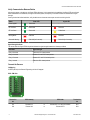
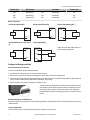
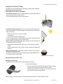
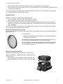
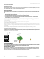
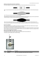
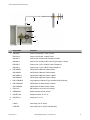
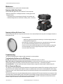
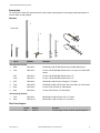
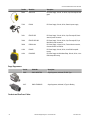
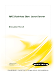
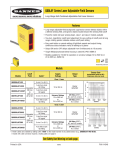
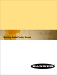
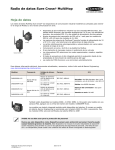
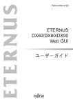
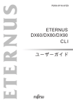
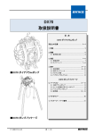
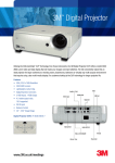
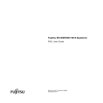
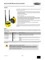
SureCross DX70 Wireless Point-to-Point Kits
The SureCross™ DX70 wireless kits include build a point-to-point network using two devices and configured I/O
Features
The SureCross™ DX70 wireless series consists of a radio frequency network built around
two devices and configured I/O.
• Wireless industrial I/O system with discrete (sourcing or sinking) inputs and outputs,
analog inputs and outputs, and a link loss output that may be selected or deselected
to be one of the four outputs
• DIP switches for user configuration
• 10 to 30V dc power input
• Site Survey analyzes the network’s signal strength and reliability
• Frequency Hopping Spread Spectrum (FHSS) technology and Time Division Multiple
Access (TDMA) control architecture combine to ensure reliable data delivery within
the unlicensed Industrial, Scientific, and Medical (ISM) band
• Transceivers provide bidirectional communication between the Gateway and Node, including fully acknowledged data transmission
• Lost RF links are detected and relevant outputs set to user-defined conditions
• External or internal antenna
For additional information, the most recent version of all documentation, and a complete
list of accessories, refer to Banner Engineering's website, www.bannerengineering.com/
surecross.
Models
When ordering the SureCross DX70 device, order the kits listed below. The kits include the Gateway, Node, mounting hardware, access
hardware, antennas, and cables. Each kit's devices ship from the factory bound and with the inputs and outputs mapped as shown in the
I/O mapping tables.
Kit Models
Frequency
Inputs and Outputs
DX70K9M6EM1
900 MHz
DX70K2M6EM1
2.4 GHz
Inputs: Four selectable discrete, two 0-20 mA analog
Outputs: Four sourcing discrete, two 0-20 mA analog
DX70K9M6ED1
900 MHz
DX70K2M6ED1
2.4 GHz
Inputs: Eight selectable discrete on the Node, four selectable discrete on the
Gateway
Outputs: Four sourcing discrete on the Node, eight sourcing discrete on the
Gateway
Internal antenna models are also available, but are not UL Listed. For more information, contact your local Banner Engineering Corp.
representative.
WARNING: Not To Be Used for Personnel Protection
Never use this product as a sensing device for personnel protection. Doing so could lead to serious injury or death. This product does NOT include the self-checking redundant circuitry necessary to
allow its use in personnel safety applications. A sensor failure or malfunction can cause either an energized or de-energized sensor output condition.
P/N 133214 rev. I
1/26/2012
0 133214
8
SureCross DX70 Wireless Point-to-Point Kits
Replacement DX70 Devices
Kit Models
DX70K9M6EM1
DX70K2M6EM1
DX70K9M6ED1
DX70K2M6ED1
Device
Frequency
Node
Replacement DX70 Device
900 MHz ISM Band
Gateway
Node
2.4 GHz ISM Band
Gateway
Node
900 MHz ISM Band
Gateway
Node
2.4 GHz ISM Band
Gateway
DX70N9X6S4P4M2M2
DX70G9X6S4P4M2M2
DX70N2X6S4P4M2M2
DX70G2X6S4P4M2M2
DX70N9X6S8P4
DX70G9X6S4P8
DX70N2X6S8P4
DX70G2X6S4P8
Device Components
3
1
4
5
6
2
1. Rotary Dials. After the DX70 devices are bound, use the rotary
dials on the Gateway to set the Network ID (NID) to a decimal value from 1 to 32.
2. LEDs. Power LED - Power indicator. A green LED indicates the
power is on. Signal LED - Provides real-time feedback regarding
RF link status and communications activity.
2
3
3. Port, NPT Gland, or Plug. If unused, install the provided plug
into the 1/2 NPT threaded port. Use PTFE tape if an IP67 seal is
required.
4. Housing. The rugged, industrial DX70 housing meets IEC IP67
standards.
5. Mounting Hole, #10/M5 Clearance. Mounting holes accept
metric M5 or UNC/UNF #10 hardware — DIN rail mount adapter
bracket available
6. Wiring Terminal Strip. The 16 wiring terminals accept wire
sizes: AWG 12-28 or 2.5 mm²
www.bannerengineering.com - tel: 763-544-3164
P/N 133214 rev. I
SureCross DX70 Wireless Point-to-Point Kits
DX70 Dimensions
The DX70 Gateway and Node use the same housing, which is also the same in size and mounting holes as the DX80 housing.
65.0
[2.56”]
7.9
[0.31”]
65.0
[2.56”]
106
[4.17”]
80.3
[3.16”]
7.65
[0.30”]
1/2” NPT
60
[2.36”]
14.67
[0.578”]
80.8
[3.18”]
Setting Up and Installing a DX70 Point-to-Point Network
To set up and install DX70 kits, follow these steps. These kits ship from the factory bound together and with their inputs and outputs
mapped as shown in the I/O mapping tables.
1.
2.
3.
4.
5.
Apply power
Verify the devices are communicating to each other
Connect the sensors
Configure the Gateway and Node
Install
Applying Power to a DX70
Connect power to the DX70 Gateway and Node by connecting your 10 to 30V dc power directly to the terminal block PWR. Connect your
ground to the GND terminal block.
1. Power (PWR)
2. Ground (GND)
P/N 133214 rev. I
www.bannerengineering.com - tel: 763-544-3164
3
SureCross DX70 Wireless Point-to-Point Kits
Verify Communication Between Radios
After applying power to the devices, the Power LED is solid green. Until communication is established, the Signal LEDs are solid red.
When communication is established, the Signal LED flashes yellow; the frequency of the flash indicates the communication signal
strength.
If testing the devices before installation, verify the devices are at least two meters apart to avoid over-driving the link.
Status
Power LED
Signal LED
Power Applied
Green solid
-
RF Link Error
Green solid
Red solid
RF Link Good
Green solid
Yellow flash
Binding Mode
Red flash
Red flash
Successful binding
Red solid (for 3 seconds)
Red solid (for 3 seconds)
Signal Strength Indicator
The rate at which the Signal LED blinks yellow indicates the signal strength between the Gateway and Node.
Blink Rate
Signal Strength
Every 1/8 second
Fewer than 3% missed packets
Every 1/4 second
Between 3% and 25% missed packets
Every 1/2 second
Between 26% and 50% missed packets
Every 1 second
More than 50% missed packets
Connect the Sensors
I/O Mapping
All DX70 pairs ship from Banner Engineering with the I/O mapped.
PWR
PWR
DX70...EM1 Kits
GND GND
AO2 AI2
AO1 AI1
DO4 DI4
DO3 DI3
DO2 DI2
DO1 DI1
4
Terminal Label
DX70 Gateway
DI1
Discrete IN 1*
DI2
Discrete IN 2
DX70 Node
Terminal Label
to
Discrete OUT 1 or Lost Link Indicator*
DO1
to
Discrete OUT 2
DO2
www.bannerengineering.com - tel: 763-544-3164
P/N 133214 rev. I
SureCross DX70 Wireless Point-to-Point Kits
Terminal Label
DX70 Gateway
DX70 Node
Terminal Label
DI3
Discrete IN 3
to
Discrete OUT 3
DO3
DI4
Discrete IN 4
to
Discrete OUT 4
DO4
AI1
Analog IN 1
to
Analog OUT 1
AO1
AI2
Analog IN 2
to
Analog OUT 2
AO2
DO1
Discrete OUT 1 or Lost Link Indicator*
from
Discrete IN 1*
DI1
DO2
Discrete OUT 2
from
Discrete IN 2
DI2
DO3
Discrete OUT 3
from
Discrete IN 3
DI3
DO4
Discrete OUT 4
from
Discrete IN 4
DI4
AO1
Analog OUT 1
from
Analog IN 1
AI1
AO2
Analog OUT 2
from
Analog IN 2
AI2
* If discrete OUT 1 is used as a lost link indicator (default) then discrete IN 1 is non-functional. A one (1) in DO1's Modbus register
indicates a lost radio link. A zero (0) indicates the radio network is operating normally. Please refer to the Configuration section to change
this setting.
DX70...ED1 Kits
The lost link indicator is not available on this model.
4P8 Model (Gateway)
8P4 Model (Node)
DO8 PWR
PWR DI8
DO7 GND
GND DI7
DO6 PWR
PWR DI6
DO5 GND
GND DI5
DO4 DI4
DO4 DI4
DO3 DI3
DO3 DI3
DO2 DI2
DO2 DI2
DO1 DI1
DO1 DI1
Terminal Label
DX70 Gateway
DX70 Node
Terminal Label
DI1
Discrete IN 1
to
Discrete OUT 1
DO1
DI2
Discrete IN 2
to
Discrete OUT 2
DO2
DI3
Discrete IN 3
to
Discrete OUT 3
DO3
DI4
Discrete IN 4
to
Discrete OUT 4
DO4
DO1
Discrete OUT 1
from
Discrete IN 1
DI1
DO2
Discrete OUT 2
from
Discrete IN 2
DI2
DO3
Discrete OUT 3
from
Discrete IN 3
DI3
DO4
Discrete OUT 4
from
Discrete IN 4
DI4
DO5
Discrete OUT 5
from
Discrete IN 5
DI5
P/N 133214 rev. I
www.bannerengineering.com - tel: 763-544-3164
5
SureCross DX70 Wireless Point-to-Point Kits
Terminal Label
DX70 Gateway
DX70 Node
Terminal Label
DO6
Discrete OUT 6
from
Discrete IN 6
DI6
DO7
Discrete OUT 7
from
Discrete IN 7
DI7
DO8
Discrete OUT 8
from
Discrete IN 8
DI8
Sensor Connections
Discrete Input Wiring (PNP)
Discrete Input Wiring (NPN)
SureCross Device
SureCross Device
DIx
DIx
PWR or SPx
Analog Input Wiring (10 to 30V dc Power)
SureCross Device
AIx
Discrete Output Wiring (PNP)
GND
SureCross Device
DOx
GND
Analog Output Wiring
SureCross Device
AOx
Refer to the sensor device data sheet for a
device specific wiring diagram.
GND
PWR
PWR
Configure the Gateway and Node
Accessing the Internal DIP Switches
To access the internal DIP switches, follow these steps:
1. Unscrew the four screws that mount the cover to the bottom housing.
2. Remove the cover from the housing without damaging the ribbon cable or the pins the cable plugs into.
3. Gently unplug the ribbon cable from the board mounted into the bottom housing. For integrated battery models (no ribbon cable) and
Class I, Division 2 certified devices (ribbon cable is glued down), skip this step.
4. Remove the black cover plate from the bottom of the device's cover.
The DIP switches are located behind the rotary dials. After making the necessary changes to the DIP switches, place the black cover plate back into position and gently push into place. Plug the ribbon cable in after verifying that
the blocked hole lines up with the missing pin. Mount the cover back onto the
housing.
DIP Switch Settings for the DX70 Devices
Use the DIP switches on the circuit board to set the following parameters. Changes made to the DIP switches affect all I/O for this device.
* Default positions.
Link Loss Output State
Use DIP switches 1 and 2 to select the state the outputs are changed to during a link loss.
6
www.bannerengineering.com - tel: 763-544-3164
P/N 133214 rev. I
SureCross DX70 Wireless Point-to-Point Kits
DIP Switches
1
2
Link Loss Output State
OFF *
OFF *
Off (discrete) or 0 mA (analog)
ON
OFF
On (discrete) or 20 mA (analog)
OFF
ON
Hold last stable state
ON
ON
Reserved
Discrete Input Type Selection
Select the discrete input type: sourcing (PNP) or sinking (NPN).
DIP Switch
3
Discrete Input Type
OFF *
PNP
ON
NPN
Use Input/Output 1 or Use Link Loss Indicator (EM1 Kit Only)
The lost link indicator option is only available with the EM1 kit. When DIP switch 4 is OFF (default position), the link loss error indicator
uses output 1 and input 1 is not available. When DIP switch 4 is ON, input 1 is mapped to output 1. For the ED1 kit, this DIP switch is
ignored.
DIP Switch
4
OFF *
ON
Use Input/Output 1 or Use Link Loss Indicator
Link Loss Error Indicator in Output 1 (Input 1 is unavailable)
Input 1 mapped to Output 1
Link Loss Timeout
The link loss timeout is the length of elapsed time during which there has been no communication between the Gateway and Node. By
default, if there has been no communication between the Gateway and Node for four seconds, the radio link has failed.
DIP Switch
5
Link Loss Timeout
OFF *
4 seconds
ON
1 second
P/N 133214 rev. I
www.bannerengineering.com - tel: 763-544-3164
7
SureCross DX70 Wireless Point-to-Point Kits
Installing Your SureCross™ Radios
The following are some recommendations for installing your wireless network components.
Mounting SureCross Devices Outdoors
Mounting SureCross Devices Outdoors
Use a Secondary Enclosure. For most outdoor applications, we recommend installing your
SureCross devices inside a secondary enclosure.
For a list of available enclosures, refer to the Accessories list.
Point Away From Direct Sunlight. When you are not using a secondary enclosure, minimize the damaging effects of ultra-violet radiation by mounting the devices to avoid facing
intense direct sunlight.
• Mount under an overhang or other source of shade,
• Install indoors, or
• Face the devices north when installing outside.
For harsh outdoor applications, consider installing your radio inside a secondary enclosure.
For a list of available enclosures, refer to the Accessories list.
Mount Vertically to Avoid Collecting Rain. When possible, mount the devices where rain
or snow will drain away from the device.
• Mount vertically so that precipitation, dust, and dirt do not accumulate on permeable
surfaces.
• Avoid mounting the devices on flat or concave surfaces, especially if the display will be
pointing up.
Moisture and Condensation. If condensation is present in any device, add a small desiccant packet to the inside of the radio.
To help vent the radios, Banner also sells a vented plug (model number BWA-HW-031) for
the 1/2" NPT port of the SureCross radios.
Vented plug for the 1/2" NPT port.
Watertight Glands and NPT Ports
Watertight Glands and Plugs
To make glands and plugs watertight, use PTFE tape and follow these steps.
To make the glands watertight:
1. Wrap four to eight passes of polytetrafluoroethylene (PTFE) tape around the
threads as close as possible to the hexagonal body of the gland.
2. Manually thread the gland into the housing hole. Never apply more than 5 inlbf of torque to the gland or its cable clamp nut.*
Seal any unused PG-7 access holes with one of the supplied black plastic plugs. To install a watertight PG-7 plug:
8
www.bannerengineering.com - tel: 763-544-3164
P/N 133214 rev. I
SureCross DX70 Wireless Point-to-Point Kits
1. Wrap four to eight passes of PTFE tape around the plug’s threads, as close as possible to the flanged surface.
2. Carefully thread the plastic plug into the vacant hole in the housing and tighten using a slotting screwdriver. Never apply more than
10 in-lbf torque to the plastic plug.
* This is not a lot of torque and is equivalent to the torque generated without using tools. If a wrench is used, apply only very light pressure. Torquing these fittings excessively damages the device.
Watertight NPT Plugs
Seal the 1/2” NPT port if it is not used. To install a watertight NPT plug:
1. Wrap 12 to 16 passes of PTFE tape evenly across the length of the threads.
2. Manually thread the plug into the housing port until reaching some resistance.
3. Using a 9/16” crescent wrench, turn the plug until all the plug’s threads are engaged by the housing port or until the resistance
doubles. Do not overtighten as this will damage the SureCross unit. These threads are tapered and will create a waterproof seal
without overtightening.
* This is not a lot of torque and is equivalent to the torque generated without using tools. If a wrench is used, apply only very light pressure. Torquing these fittings excessively damages the device.
Replacing the Rotary Dial Access Cover
Check the rotary dial access cover o-ring every time the access cover is removed. Replace the o-ring when it is damaged, discolored, or
showing signs of wear.
The o-ring should be:
• Seated firmly against the threads without stretching to fit or without bulging loosely, and
• Pushed against the flanged cover.
When removing or closing the rotary dial access cover, manually twist the cover into position. Do not allow cross-threading between the cover and the devce's face.
Once the cover is in place and manually tightened, use a small screwdriver (no longer than
five inches total length) as a lever to apply enough torque to bring the rotary dial access
cover even with the cover surface.
Replacing the Main Body Gasket
Check the main body gasket every time a SureCross™ device is opened.
Replace the gasket when it is damaged, discolored, or showing signs of wear.
The gasket must be:
• Fully seated within its channel along the full length of the perimeter, and
• Positioned straight within the channel with no twisting, stress, or stretching.
P/N 133214 rev. I
www.bannerengineering.com - tel: 763-544-3164
9
SureCross DX70 Wireless Point-to-Point Kits
Other Installation Requirements
Reduce Chemical Exposure
Before installing any devices in a chemically harsh environment, contact the manufacturer for more information regarding the life-expectancy. Solvents, oxidizing agents, and other chemicals will damage the devices.
Minimize Mechanical Stress
Although these radio devices are very durable, they are sophisticated electronic devices that are sensitive to shock and excessive loading.
• Avoid mounting the devices to an object that may be shifting or vibrating excessively. High levels of static force or acceleration may
damage the housing or electronic components.
• Do not subject the devices to external loads. Do not step on them or use them as handgrips.
• Do not allow long lengths of cable to hang from the glands on the Gateway or Node. Cabling heavier than 100 grams should be
supported instead of allowed to hang from the housing.
It is the user’s responsibility to install these devices so they will not be subject to overvoltage transients. Always ground the devices in
accordance with local, state, or national regulations.
Installation Quick Tips
The following are some quick tips for improving the installation of wireless network components.
Create a Clear Communication Path
Wireless communication is hindered by radio interference and obstructions in the path between the transmitter and receiver. To achieve
the best radio performance, carefully consider the installation locations for the Gateways and Nodes and select locations without obstructions in the path.
For more information about antennas, please refer to the Antenna Basics reference guide, Banner document p/n 132113.
Increase the Height of the Antennas
Position the external antenna vertically for optimal RF communication. If necessary, consider changing the height of the SureCross radio,
or its antenna, to improve reception. For outdoor applications, mounting the antenna on top of a building or pole may help achieve a lineof-sight radio link with the other radios in the network.
Line of sight
Node
Gateway
No line of sight
Avoid Collocating Radios
When the radio network’s master device is located too close to another radio device, communications between all devices is interrupted.
For this reason, do not install a Gateway device within two meters of another Gateway or Node.
Be Aware of Seasonal Changes
When conducting the initial Site Survey, the fewest possible missed packets for a given link is better. However, seasonal changes may
affect the signal strength and the total signal quality. Radios installed outside with 50% missed packets in the winter months may have
80% or more missed packets in the summer when leaves and trees interfere with radio reception.
10
www.bannerengineering.com - tel: 763-544-3164
P/N 133214 rev. I
SureCross DX70 Wireless Point-to-Point Kits
Node
Gateway
A good signal strength in winter doesn’t
always mean you’ll get the same signal
strength the rest of the year.
Node
Gateway
During spring and summer, leaves may
block more of the radio signal.
Basic Remote Antenna Installation
A remote antenna system is any antenna system where the antenna is not connected directly to the radio. These systems typically use
coaxial cable to connect the antenna to the radio. When installing a remote antenna system, always include a lightning arrestor or coaxial
surge suppressor in the system. Remote antenna systems installed without surge protection invalidate the warranty of the radio devices.
Surge suppressors should be properly grounded and mounted at ground level near where the cabling enters a building. Install the surge
suppressor indoors or inside a weatherproof enclosure to minimize corrosion or component deterioration. For best results, mount the
surge suppressor as close to the ground as possible to minimize the length of the ground connection and use a single-point ground
system to avoid creating ground loops.
For more detailed information about how antennas work and how to install them, refer to Antenna Basics, Banner document 132113 (also
included as a chapter within the product manual).
1
1. Antenna mounted remotely from the radio device.
2. Coaxial cable
3. Surge suppressor
4. Ground wire to a single-point ground system
2
3
4
I/O Isolation. When connecting analog and discrete I/O to external equipment such as VFDs (Variable Frequency Drives), it may be
appropriate to install interposing relays and/or loop isolation devices to protect the DX80 unit from transients, noise, and ground plane
interference originating from devices or the environment. Contact Banner Engineering Corp. for more information.
P/N 133214 rev. I
www.bannerengineering.com - tel: 763-544-3164
11
SureCross DX70 Wireless Point-to-Point Kits
Weatherproofing Remote Antenna Installations
Prevent water damage to the cable and connections by sealing the connections with rubber splicing tape and electrical tape.
Step 1: Verify both connections are clean and dry before connecting the antenna cable to the antenna or other cable and hand-tightening.
Step 2: Tightly wrap the entire connection with rubber splicing tape.
Begin wrapping the rubber splicing tape one inch away from the connection and continue wrapping until you are one inch past the other
end of the connection. Each new round of tape should overlap about half the previous round.
Step 3: Protect the rubber splicing tape from UV damage by tightly wrapping electrical tape on top of the rubber splicing tape. The
electrical tape should completely cover the rubber splicing tape and overlap the rubber tape by one inch on each side of the connection.
Antenna Installation
Always install and properly ground a qualified surge suppressor when installing a remote antenna system. Remote antenna configurations installed without surge suppressors invalidate the manufacturer's warranty.
Always keep the ground wire as short as possible and make all ground connections to a single-point ground system to ensure no ground
loops are created. No surge suppressor can absorb all lightning strikes. Do not touch the SureCross™ device or any equipment connected to the SureCross device during a thunderstorm.
Mounting an RP-SMA Antenna Directly to the Cabinet
This antenna mounts directly to the outside of the box, with the SureCross device mounted inside the box.
This situation may be used either inside or outside the building.
1
2
3
4, 5
1
12
Model Number
Description
BWA-9O2-C
Antenna, Omni, 902-928 MHz, 2 dBd, Rubber Swivel, RP-SMA MALE
www.bannerengineering.com - tel: 763-544-3164
P/N 133214 rev. I
SureCross DX70 Wireless Point-to-Point Kits
Model Number
Description
BWA-2O2-C
Antenna, Omni, 2.4 GHz, 2 dBd, Rubber Swivel, RP-SMA MALE
BWA-2O5-C
Antenna, Omni, 2.4 GHz, 5 dBd, Rubber Swivel, RP-SMA MALE
BWA-2O7-C
Antenna, Omni, 2.4 GHz, 7 dBd, Rubber Swivel, RP-SMA MALE
2
BWC-LMRSFRPB
Surge Suppressor, Bulkhead, RP-SMA Type, 900 MHz/2.4 GHz
3
BWC-1MRSFRSB02
RG58 Cable, RP-SMA TO RP-SMA Female Bulkhead, 0.2 m
BWC-1MRSFRSB1
RG58 Cable, RP-SMA TO RP-SMA Female Bulkhead, 1 m
BWC-1MRSFRSB2
RG58 Cable, RP-SMA TO RP-SMA Female Bulkhead, 2 m
BWC-1MRSFRSB4
RG58 Cable, RP-SMA TO RP-SMA Female, Bulkhead, 4 m
4
DIN-35-105
DIN Rail section, 105 mm long, 35 mm design
5
SMBDX80DIN
DIN Rail Bracket Assembly for DX70 and DX80 models.
Mounting an RP-SMA Antenna Remotely
This antenna mounts remotely from the box, with the SureCross device mounted inside the box.
This situation may be used either inside or outside the building, though a Yagi antenna is usually used in outdoors applications while an
omni-directional antenna may be used either inside a building or outside.
1
2
3
4
5, 6
7, 8
9
1
Model Number
Description
BWA-9O2-C
Antenna, Omni, 902-928 MHz, 2 dBd, Rubber Swivel, RP-SMA MALE
BWA-9O5-C
Antenna, Omni, 902-928 MHz, 5 dBd, Rubber Swivel, RP-SMA MALE
BWA-2O2-C
Antenna, Omni, 2.4 GHz, 2 dBd, Rubber Swivel, RP-SMA MALE
BWA-2O5-C
Antenna, Omni, 2.4 GHz, 5 dBd, Rubber Swivel, RP-SMA MALE
P/N 133214 rev. I
www.bannerengineering.com - tel: 763-544-3164
13
SureCross DX70 Wireless Point-to-Point Kits
Model Number
Description
BWA-2O7-C
Antenna, Omni, 2.4 GHz, 7 dBd, Rubber Swivel, RP-SMA MALE
BWC-1MRSFRSB02
RG58 Cable, RP-SMA TO RP-SMA Female Bulkhead, 0.2 m
BWC-1MRSFRSB1
RG58 Cable, RP-SMA TO RP-SMA Female Bulkhead, 1 m
BWC-1MRSFRSB2
RG58 Cable, RP-SMA TO RP-SMA Female Bulkhead, 2 m
BWC-1MRSFRSB4
RG58 Cable, RP-SMA TO RP-SMA Female, Bulkhead, 4 m
3
BWC-LMRSFRPB
Surge Suppressor, Bulkhead, RP-SMA Type, 900 MHz/2.4 GHz
4
BWC-1MRSFRSB02
RG58 Cable, RP-SMA TO RP-SMA Female Bulkhead, 0.2 m
BWC-1MRSFRSB1
RG58 Cable, RP-SMA TO RP-SMA Female Bulkhead, 1 m
BWC-1MRSFRSB2
RG58 Cable, RP-SMA TO RP-SMA Female Bulkhead, 2 m
BWC-1MRSFRSB4
RG58 Cable, RP-SMA TO RP-SMA Female, Bulkhead, 4 m
5
DIN-35-105
DIN Rail section, 105 mm long, 35 mm design
6
SMBDX80DIN
Bracket Assembly, DIN Rail, for DX80
7
BWA-EF14128
Fiberglass enclosure, 14”x 12” x 8”
8
BWA-PA1412
Internal panel, 14” x 12”
PS24DX
Power Supply, 24V dc, 200 mA
PS24DXSR
Power Supply, 24V dc, 200 mA, Solid State Relay
2
9*
* This example image depicts a DX80 radio with a PS24x power supply. The example installation may also work with the DX70 radios or
MultiHop radios. However, the DX81 and DX81P6 FlexPower Battery Supply Modules can only power FlexPower devices. The battery
supply modules cannot be used with any 10-30V dc-only powered devices and cannot be used with the DX70 radios.
Mounting N-Type Antennas Remotely
This antenna mounts remotely from the box, with the SureCross device mounted inside the box.
This situation may be used either inside or outside the building, though a Yagi antenna is usually used in outdoors applications while an
omni-directional antenna may be used either inside a building or outside.
14
www.bannerengineering.com - tel: 763-544-3164
P/N 133214 rev. I
SureCross DX70 Wireless Point-to-Point Kits
2
3
1
4
5, 6
7, 8
9
Model Number
Description
BWA-9Y6-A
Antenna, Yagi, 900 MHz, 6.5 dBd, N Female
BWA-9Y10-A
Antenna, Yagi, 900 MHz, 10 dBd, N Female
BWA-9O6-A
Antenna, Omni, 900 MHz, 6 dBd, Fiberglass, N Female
BWA-9O5-B
Antenna, Omni, 900 MHz, 5 dBd/7.2 dBi, With ground plane, N Female
BWA-2O8-A
Antenna, Omni, 2.4 GHz, 8.5 dBi, N Female, Fiberglass 24”
BWA-2O6-A
Antenna, Omni, 2.4 GHz, 6 dBi, N Female, Fiberglass 16”
BWC-4MNFN3
LMR400 Cable, N-Male to N-Female, 3 Meters
BWC-4MNFN6
LMR400 Cable, N-Male to N-Female, 6 Meters
BWC-4MNFN15
LMR400 Cable, N-Male to N-Female, 15 Meters
BWC-4MNFN30
LMR400 Cable, N-Male to N-Female, 30 Meters
3
BWC-LFNBMN-DC
Surge Suppressor, Bulkhead, N-Type, 900 MHz/2.4 GHz, dc-Blocking
4
BWC-1MRSMN05
LMR200 Cable, RP-SMA to N-Male, 0.5 Meters
BWC-1MRSMN2
LMR200 Cable, RP-SMA to N-Male, 2 Meters
5
DIN-35-105
DIN Rail section, 105 mm long, 35 mm design
6
SMBDX80DIN
Bracket Assembly, DIN Rail, for DX80
7
BWA-EF14128
Fiberglass enclosure, 14”x 12” x 8”
8
BWA-PA1412
Internal panel, 14” x 12”
PS24DX
Power Supply, 24V dc, 200 mA
PS24DXSR
Power Supply, 24V dc, 200 mA, Solid State Relay
1
2
9*
P/N 133214 rev. I
www.bannerengineering.com - tel: 763-544-3164
15
SureCross DX70 Wireless Point-to-Point Kits
* This example image depicts a DX80 radio with a PS24x power supply. The example installation may also work with the DX70 radios or
MultiHop radios. However, the DX81 and DX81P6 FlexPower Battery Supply Modules can only power FlexPower devices. They battery
supply modules cannot be used with any 10-30V dc-only powered devices and cannot be used with the DX70 radios.
Advanced Setup
Binding the DX70 Gateway and Node
DX70 Gateway and Node kits ship from the factory bound to each other. You should only need to bind devices if you are replacing one of
the devices in your existing pair.
Binding Nodes to their Gateway ensures the Nodes only exchange data with the Gateway they are bound to. The Gateway automatically
generates a unique extended addressing code when the Gateway enters binding mode. This code is then transmitted to all radios within
range that are also in binding mode. After a Node is bound, the Node accepts data only from the Gateway to which it is bound. The
extended addressing code defines the network, and all radios within a network must use the same code.
If the power is applied and the Power LED is solid green and the Signal LED is solid red for more than thirty seconds (indicating an RF
link error), the devices need to be bound. To bind your DX70 pair, follow these instructions.
1. Install the supplied antennas to both the Gateway and Node.
2. Apply power to both devices and position the Gateway and Node at least two meters apart.
The Power LED is solid green and the Signal LED is solid red, indicating an RF link error.*
3. Remove the rotary dial access covers.
4. On the Gateway, set both the left and right rotary dials to 0, then set both the left and right rotary dials to F.
The Gateway enters binding mode. Note that both rotary dials for each device must be changed to F after applying power, not before
applying power. Both the POWER and SIGNAL LEDs flash red.
5. On the Node, set both the left and right rotary dials to 0, then set both rotary dials to F.
The Node enters binding mode and waits for the Gateway to respond. Both the Gateway’s and Node’s LEDs alternately flash red
during pairing. After the devices are successfully bound, the Node’s LEDs are solid red for a few seconds and the Node automatically
exits binding mode. The Node Power LED is solid green and Signal LED is solid red, indicating the Node is bound. Binding should
take less than twenty seconds.
6. Change the Gateway’s rotary dials to a valid Network ID.
Valid Network IDs are 01 through 32, in decimal, established using both rotary dials. The left dial may be set to 0, 1, 2, or 3. The right
dial may be set from 0 to 9 when the left dial is at 0, 1, or 2; or set to 0 through 2 when the left dial is at 3. (Positions A through F are
invalid network ID numbers.)**
7. The Node automatically synchronizes to the Gateway and establishes a radio link in less than a minute.
When a radio link is established, the Power LED is green and the Signal LED flashes yellow on both devices to indicate the signal
strength.
8. On the Node, set both the left and right rotary dials back to 0, or any position other than F.
9. Replace both the rotary dial access covers.
Regardless of the position of the Node’s rotary dials, the DX70 devices within this bound pair maintain a radio link. For successful binding, the Gateway and Node should be at least two meters apart and have the antennas installed.
* Unbound devices will have a solid green Power LED and solid red Signal LED thirty seconds after power up. Bound devices have a
solid green Power LED and a flashing yellow Signal LED within thirty seconds of power up.
** When multiple networks operate in the same area, assign a unique Network ID (NID) to the Gateway device within each bound pair.
For more information about collocated networks and Network IDs, refer to the Troubleshooting section.
16
www.bannerengineering.com - tel: 763-544-3164
P/N 133214 rev. I
SureCross DX70 Wireless Point-to-Point Kits
Maintenance
Follow these instructions to perform basic maintenance tasks.
Replacing the Main Body Gasket
Check the main body gasket every time a SureCross™ device is opened.
Replace the gasket when it is damaged, discolored, or showing signs of wear.
The gasket must be:
• Fully seated within its channel along the full length of the perimeter, and
• Positioned straight within the channel with no twisting, stress, or stretching.
Replacing the Rotary Dial Access Cover
Check the rotary dial access cover o-ring every time the access cover is removed. Replace the o-ring when it is damaged, discolored, or
showing signs of wear.
The o-ring should be:
• Seated firmly against the threads without stretching to fit or without bulging loosely, and
• Pushed against the flanged cover.
When removing or closing the rotary dial access cover, manually twist the cover into position. Do not allow cross-threading between the cover and the devce's face.
Once the cover is in place and manually tightened, use a small screwdriver (no longer than
five inches total length) as a lever to apply enough torque to bring the rotary dial access
cover even with the cover surface.
Troubleshooting
The following troubleshooting tips include some basic instructions for common problems.
Troubleshooting Problems on Your DX70 Network
No LEDs. Recheck the power connections and power requirements. DX70 devices require 10 to 30V dc.
Signal LED is solid red or flashing red for more than 30 seconds. If the devices are less than two meters apart, they may not communicate properly (radios may saturate). The devices may be too far apart to achieve sync – consult factory for options.
Collocated Networks. To prevent interference between collocated networks, assign each wireless network a different Network ID.
RF Link Timeout and Recovery
The SureCross™ DX70 wireless devices employ a deterministic link timeout method to address RF link interruption or failure. As soon as
a specific RF link fails, all pertinent wired outputs are brought to a predefined state until the link is recovered (default DIP switch setting).
Through this process, users of Banner wireless networks can be assured that disruptions in the communications link result in predictable
system behavior.
The link time-out feature uses a fully-acknowledged polling method to determine the RF link status of each device on the network. If after
a specified number of sequential polling cycles a device does not acknowledge a message, the devices consider the link to be timed out.
Once a link has timed out, the units must send and receive a specified number of good RF communications packets before the link is
reinstated. Outputs are restored to current values when the link is recovered.
P/N 133214 rev. I
www.bannerengineering.com - tel: 763-544-3164
17
SureCross DX70 Wireless Point-to-Point Kits
The lost link option is only available on the 4P4M2M2 models.
1. The RF link between the devices has timed out. In this example, the lost link is energized and the outputs have been programmed by
the DIP switches to go to their de-energized states (default DIP switch position).
2. The RF link between the devices has recovered and the outputs return to their current states.
A wireless network can be hindered by radio interference and by obstructions in the path of the receiver and transmitter. To achieve the
best radio performance possible, carefully consider the installation locations for all devices. The need for a clear path increases as the
transmission distance increases.
Collocated Networks
To prevent interference between collocated wireless networks, assign each wireless network a different Network ID. The Network ID is a
unique identifier assigned to each wireless network using the rotary dials on the Gateway.
Setting the Network ID on the DX70s
The Network ID is a unique identifier assigned to each wireless network that minimizes the chances of two collocated networks interfering
with each other. Assigning different NIDs to different networks improves collocation performance in dense installations.
To assign the Network ID for the DX70 network, use the Gateway's rotary dials. Valid Network IDs are 01 through 32, in decimal, establish using both rotary dials on the Gateway.
1. Set the Gateway's left dial to either 0, 1, 2, or 3.
2. Set the Gateway's right dial to any number from 0 to 9 when the left dial is at 0, 1, or 2; or set to 0 through 2 when the left dial is at 3.
(Positions A through F are invalid network ID numbers.)
18
www.bannerengineering.com - tel: 763-544-3164
P/N 133214 rev. I
SureCross DX70 Wireless Point-to-Point Kits
Accessories
The accessories list includes FCC approved antennas, antenna cabling, surge suppressors, power supplies, replacement batteries, enclosures, cables, and other hardware.
Antennas
3
Not to scale
7
4
5
6
1
8
2
Part No.
Model No.
Description
Omni-Directional Antennas
1
76908
BWA-9O2-C
902-928 MHz, 2 dBi, RP-SMA Male (ships with 900 MHz DX80 devices)
2
77816
BWA-2O2-C
2.4 GHz, 2 dBi, RP-SMA Male, Rubber swivel, 3 1/4” (ships with 2.4 GHz DX80
devices)
77817
BWA-2O5-C
2.4 GHz, 5 dBi, RP-SMA Male, Rubber swivel, 6 1/2”
77818
BWA-2O7-C
2.4 GHz, 7 dBi, RP-SMA Male, Rubber swivel, 9 1/4”
3
77481
BWA-9O6-A
902-928 MHz, 6 dBd, N Female, Fiberglass, 71.5” Outdoor
4
77819
BWA-9O5-B
902-928 MHz, 5 dBd/7.2 dBi, N Female, with Ground Plane, 32” Indoor/Outdoor
5
81080
BWA-2O8-A
2.4 GHz, 8.5 dBi, N Female, 24” Indoor/Outdoor
6
81081
BWA-2O6-A
2.4 GHz, 6 dBi, N Female, 16” Indoor/Outdoor
Directional (Yagi) Antennas
7
77479
BWA-9Y6-A
890-960 MHz, 6.5 dBd, N Female, 6.8” x 13” Outdoor
8
77480
BWA-9Y10-A
890-960 MHz, 10 dBd, N Female, 6.8” x 24” Outdoor
Other Power Supplies
P/N 133214 rev. I
Part No.
Model No.
Description
65837
SPS101Q
DC Power Supply, 120 mA, 12–30V dc, 5-pin Euro-style QD
www.bannerengineering.com - tel: 763-544-3164
19
SureCross DX70 Wireless Point-to-Point Kits
Part No.
Model No.
Description
65848
SPS101QP
DC Power Supply, 120 mA, 12–30V dc, 5-pin Euro-style QD and
pigtail
77422
PS24W
DC Power Supply, 500 mA, 24V dc, Demo kit power supply
74321
EZAC-E-QE5
DC Power Supply, 700 mA, 24V dc, 5-pin Euro-style QD, Hardwired AC power connection
73466
EZAC-E-QE5-QS5
DC Power Supply, 700 mA, 24V dc, 5-pin Euro-style QD, 5-pin
Mini QD AC power connection
76809
PSDINA-24-4
DC Power Supply, 4 Amps, 24V dc, Terminal block connection,
Converts 85-264V ac 50/60 Hz
11280
PS24DX
DC Power Supply, 200 mA, 24V dc, in the DX80 low-profile
housing
11830
PS24DXSR
DC Power Supply with Solid State Relay, 200 mA, 24V dc, in the
DX80 low-profile housing
Surge Suppressors
Part No.
Model No.
Description
79296
BWC-LMRSFRPB
Surge Suppressor, bulkhead, RP-SMA Type
12477
BWC-LFNBMN-DC
Surge Suppressor, bulkhead, N-Type, dc Blocking
Cordsets and SureCross Cables
20
www.bannerengineering.com - tel: 763-544-3164
P/N 133214 rev. I
SureCross DX70 Wireless Point-to-Point Kits
Antenna Cables
2
1
1
2
3
3
Part No.
Model No.
Description
77486
BWC-1MRSMN05
LMR200 RP-SMA to N Male, 0.5M
77820
BWC-1MRSMN2
LMR200 RP-SMA to N Male, 2M
78544
BWC-1MRSFRSB0.2
RG58, RP-SMA to RP-SMAF Bulkhead, 0.2M
78337
BWC-1MRSFRSB1
RG58, RP-SMA to RP-SMAF Bulkhead, 1M
78338
BWC-1MRSFRSB2
RG58, RP-SMA to RP-SMAF Bulkhead, 2M
77488
BWC-1MRSFRSB4
RG58, RP-SMA to RP-SMAF Bulkhead, 4M
77489
BWC-4MNFN3
LMR400 N Male to N Female, 3M
77490
BWC-4MNFN6
LMR400 N Male to N Female, 6M
77821
BWC-4MNFN15
LMR400 N Male to N Female, 15M
77822
BWC-4MNFN30
LMR400 N Male to N Female, 30M
Euro-Style Cordsets
Part No.
Model No.
Description
78382
BWA-QD5.5
Prewired 5-pin Euro connector, 1/2-14 NBSM
78383
BWA-QD8.5
Prewired, 8-pin Euro connector, 1/2-14 NBSM
78384
BWA-QD12.5
Prewired 12-pin Euro connector, 1/2-14 NBSM
58912
FIC-M12F4
Euro-Style Field-Wireable Connector 4-pin Female Straight
62837
DEUR-506.6C
Cordset, 5-pin Euro-style, double ended, male/female, 1.83m
2. White
72333
DEE2R-51D
Cordset, 5-pin Euro-style, double ended, male/female, 0.3m
3. Blue
72334
DEE2R-53D
Cordset, 5-pin Euro-style, double ended, male/female, 1m
4. Black
72636
DEE2R-58D
Cordset, 5-pin Euro-style, double ended, male/female, 2.4m
5. Gray
71038
MQDC1-501.5
Cordset, 5-pin Euro-style, single ended, female, 0.5m
12597
MQDMC-401
Cordset, 4-pin Euro-style, single ended, male, straight, 0.5m, longer
pigtail ends for DX80…C models
51127
MQDC1-506
Cordset, 5-pin Euro-style, single ended, female, 1.83m
47812
MQDC1-515
Cordset, 5-pin Euro-style, single ended, female, 4.57m
47814
MQDC1-530
Cordset, 5-pin Euro-style, single ended, female, 9.14m
51128
MQDC1-506RA
Cordset, 5-pin Euro-style, single ended, female, right-angle, 1.83m
47813
MQDC1-515RA
Cordset, 5-pin Euro-style, single ended, female, right-angle, 4.57m
1. Brown
P/N 133214 rev. I
www.bannerengineering.com - tel: 763-544-3164
21
SureCross DX70 Wireless Point-to-Point Kits
Part No.
Model No.
Description
47815
MQDC1-530RA
Cordset, 5-pin Euro-style, single ended, female, right-angle, 9.14m
Right-angle cordsets are not compatible with the DX70 devices. When facing the Node or Gateway toward you and the quick disconnect
connection is facing down, the right-angle cables exit to the right.
If using the communication lines, the cable length cannot exceed 3 meters, or 10 feet.
When using the FlexPower Node with integrated battery, use the double ended cordsets. For a FlexPower Node with external power
supply, use the single ended cordset.
Other Cables
Part No.
Model No.
Description
79985
BWA-RIBBON-001
Ribbon cable, 20-pin DBL socket
10200
BWA-HW-010
Cable, FlexPower Current Monitoring
Enclosures and Relay Boxes
Part No.
Model No.
Description
11320
BWA-EF14128
Enclosure Fiberglass Hinged 14"x12"x8"
11321
BWA-EF1086
Enclosure Fiberglass Hinged 10"x8"x6"
11322
BWA-EF866
Enclosure Fiberglass Hinged 8"x6"x6"
11326
BWA-PA1412
Panel, 14 x 12
11327
BWA-PA108
Panel, 10 x 8
11327
BWA-PA86
Panel, 8 x 6
11329
BWA-PM12
Pole Mount, 12 inch
11340
BWA-PM8
Pole Mount, 8 inch
11341
BWA-PM6
Pole Mount, 6 inch
11346
IB6RP
Interface Relay Box, 18-26V dc inputs, isolated relay outputs (not shown)
Replacement Parts for DX70 Models
Part No.
Model No.
Description
Items
76907
BWA-HW-001
Mounting Hardware Kit
Screw, M5-0.8 x 25 mm, SS (4)
22
www.bannerengineering.com - tel: 763-544-3164
P/N 133214 rev. I
SureCross DX70 Wireless Point-to-Point Kits
Part No.
Model No.
Description
Items
Screw, M5-0.8 x 16mm, SS (4)
Hex nut, M5-0.8mm, SS (4)
Bolt, #8-32 x 3/4”, SS (4)
76910
BWA-HW-003
PTFE Tape
16328
BWA-HW-004
Replacement Seals
O-ring, rotary access cover, PG21 (2)
O-ring, body gasket (2)
Access cover, rotary, clear plastic (2)
79438
BWA-CG.5-10
Cable Glands, 1/2-inch NPT
10 pieces, cordgrips for cable diameters 0.17’’ to 0.45’’
79984
BWA-HP.5-10
Dummy Hole Plugs, 1/2-inch NPT
10 pieces
77161
SMBDX80DIN
Bracket assembly, DIN rail, flat mount
Radio Certifications
Banner's SureCross product line is certified by the FCC, European Union, and many other countries for operation within specific radio
frequencies.
FCC Certification, 900MHz
The DX80 Module complies with Part 15 of the FCC rules and regulations.
FCC ID: TGUDX80 This device complies with Part 15 of the FCC Rules. Operation is subject to the following two conditions: (1) this
device may not cause harmful interference, and (2) this device must accept any interference received, including interference that may
cause undesired operation.
FCC Notices
IMPORTANT: The DX80 Modules have been certified by the FCC for use with other products without any further certification (as per FCC
section 2.1091). Changes or modifications not expressly approved by the manufacturer could void the user’s authority to operate the
equipment.
IMPORTANT: The DX80 Modules have been certified for fixed base station and mobile applications. If modules will be used for portable
applications, the device must undergo SAR testing.
IMPORTANT: If integrated into another product, the FCC ID label must be visible through a window on the final device or it must be
visible when an access panel, door, or cover is easily removed. If not, a second label must be placed on the outside of the final device
that contains the following text: Contains FCC ID: TGUDX80.
Note
This equipment has been tested and found to comply with the limits for a Class B digital device, pursuant to Part 15 of the FCC Rules.
These limits are designed to provide reasonable protection against harmful interference in a residential installation. This equipment generates, uses, and can radiate radio frequency energy and, if not installed and used in accordance with the instructions, may cause harmful interference to radio communications. However, there is no guarantee that interference will not occur in a particular installation. If this
equipment does cause harmful interference to radio or television reception, which can be determined by turning the equipment off and
on, the user is encouraged to try to correct the interference by one or more of the following measures:
•
•
•
•
Reorient or relocate the receiving antenna,
Increase the separation between the equipment and receiving module,
Connect the equipment into an outlet on a circuit different from that to which the receiving module is connected, and/or
Consult the dealer or an experienced radio/TV technician for help.
Antenna Warning WARNING: This device has been tested with Reverse Polarity SMA connectors with the antennas listed in Table 1
Appendix A. When integrated into OEM products, fixed antennas require installation preventing end-users from replacing them with nonapproved antennas. Antennas not listed in the tables must be tested to comply with FCC Section 15.203 (unique antenna connectors)
and Section 15.247 (emissions).
P/N 133214 rev. I
www.bannerengineering.com - tel: 763-544-3164
23
SureCross DX70 Wireless Point-to-Point Kits
FCC Approved Antennas
WARNING: This equipment is approved only for mobile and base station transmitting devices. Antenna(s) used for this transmitter must
be installed to provide a separation distance of at least 20 cm from all persons and must not be collocated or operating in conjunction
with any other antenna or transmitter.
DX80 Module may be used only with Approved Antennas that have been tested with this module.
Model Number
Antenna Type
Maximum Gain
Integral antenna
Unity gain
BWA-9O1-x
Omni, 1/4 wave dipole
≤2 dBi
BWA-9O2-C
Omni, 1/2 wave dipole, Swivel
≤2 dBi
BWA-9O6-A
Omni Wideband, Fiberglass Radome
≤8.2 dBi
BWA-9O5-B
Omni Base Whip
≤7.2 dBi
BWA-9Y10-A
Yagi
≤10 dBi
Table 1. Type certified antennas
FCC Certification, 2.4GHz
The DX80 Module complies with Part 15 of the FCC rules and regulations.
FCC ID: UE300DX80-2400 This device complies with Part 15 of the FCC Rules. Operation is subject to the following two conditions: (1)
this device may not cause harmful interference, and (2) this device must accept any interference received, including interference that may
cause undesired operation.
FCC Notices
IMPORTANT: The DX80 Modules have been certified by the FCC for use with other products without any further certification (as per FCC
section 2.1091). Changes or modifications not expressly approved by the manufacturer could void the user’s authority to operate the
equipment.
IMPORTANT: The DX80 Modules have been certified for fixed base station and mobile applications. If modules will be used for portable
applications, the device must undergo SAR testing.
IMPORTANT: If integrated into another product, the FCC ID label must be visible through a window on the final device or it must be
visible when an access panel, door, or cover is easily removed. If not, a second label must be placed on the outside of the final device
that contains the following text: Contains FCC ID: UE300DX80-2400.
Note
This equipment has been tested and found to comply with the limits for a Class B digital device, pursuant to Part 15 of the FCC Rules.
These limits are designed to provide reasonable protection against harmful interference in a residential installation. This equipment generates, uses, and can radiate radio frequency energy and, if not installed and used in accordance with the instructions, may cause harmful interference to radio communications. However, there is no guarantee that interference will not occur in a particular installation. If this
equipment does cause harmful interference to radio or television reception, which can be determined by turning the equipment off and
on, the user is encouraged to try to correct the interference by one or more of the following measures:
•
•
•
•
Reorient or relocate the receiving antenna,
Increase the separation between the equipment and receiving module,
Connect the equipment into an outlet on a circuit different from that to which the receiving module is connected, and/or
Consult the dealer or an experienced radio/TV technician for help.
Antenna Warning WARNING: This device has been tested with Reverse Polarity SMA connectors with the antennas listed in Table 1
Appendix A. When integrated into OEM products, fixed antennas require installation preventing end-users from replacing them with nonapproved antennas. Antennas not listed in the tables must be tested to comply with FCC Section 15.203 (unique antenna connectors)
and Section 15.247 (emissions).
24
www.bannerengineering.com - tel: 763-544-3164
P/N 133214 rev. I
SureCross DX70 Wireless Point-to-Point Kits
FCC Approved Antennas
WARNING: This equipment is approved only for mobile and base station transmitting devices. Antenna(s) used for this transmitter must
be installed to provide a separation distance of at least 20 cm from all persons and must not be collocated or operating in conjunction
with any other antenna or transmitter.
DX80 Module may be used only with Approved Antennas that have been tested with this module.
Model Number
Antenna Type
Maximum Gain
Integral antenna
Unity gain
BWA-2O2-C
Omni, 1/2 wave dipole, Swivel
≤2 dBi
BWA-2O5-C
Omni, Collinear, Swivel
≤5 dBi
BWA-2O7-C
Omni, Coaxial Sleeve, Swivel
≤7 dBi
Certified For Use in the Following Countries
The SureCross radio devices are approved for use in the following countries.
Radio Modules
Country
900 MHz (150 mW)
900 MHz (1 Watt)
2.4 GHz (65 mW)
Australia
x
Austria
x
Bahamas, The
x
x
Bahrain (Kingdom of)
x
Belgium
x
Brazil
x
Bulgaria
x
Canada
x
x
x
Chile
x
China (People's Republic of)
x
Colombia
x
x
Cyprus
x
Czech Republic
x
Denmark
x
Estonia
x
Egypt
x
Finland
x
France
x
Germany
x
Greece
x
Hungary
x
Iceland
x
India
x
P/N 133214 rev. I
www.bannerengineering.com - tel: 763-544-3164
25
SureCross DX70 Wireless Point-to-Point Kits
Radio Modules
Country
900 MHz (150 mW)
900 MHz (1 Watt)
2.4 GHz (65 mW)
Ireland
x
Israel
x*
Italy
x
Latvia
x
Liechtenstein
x
Lithuania
x
Luxembourg
x
Malta
x
Mexico
x
x
x
Netherlands
x
New Zealand
x
Norway
x
Panama
x
x
Poland
x
Portugal
x
Romania
x
Saudi Arabia (Kingdom of)
x
Singapore
x
Slovakia
x
Slovenia
x
South Africa
x
Spain
x
Sweden
x
Switzerland
x
Taiwan
x **
Thailand
x
United Arab Emirates
x
United Kingdom
x
United States of America
x
x
x
Bulgaria - Authorization required for outdoor and public service use.
Canada- This Class A digital apparatus meets all requirements of the Canadian Interference Causing Equipment Regulations. Operation
is subject to the following two conditions: (1) this device may not cause harmful interference, and (2) this device must accept any interference received, including interference that may cause undesired operation.
26
www.bannerengineering.com - tel: 763-544-3164
P/N 133214 rev. I
SureCross DX70 Wireless Point-to-Point Kits
Cet appareil numérique de la classe A respecte toutes les exigences du Règlement sur le matériel brouiller du Canada. Le present appareil numérique n’emet pas de bruits radioélectriques dépassant les limites applicables aux appareils numeriques de le Classe A préscrites dans le Reglement sur le brouillage radioélectrique édits par le ministere des Communications du Canada.
France - In Guyane (French Guiana) and La Réunion (Reunion Island), outdoor use not allowed.
* Israel - DX80 and DX99 models are certified for the external antenna models only.
Italy - If used outside of own premises, general authorization is required.
Luxembourg - General authorization is required for public service.
** Taiwan - Taiwan is certified to operate specific DX70, DX80, and DX99 models. For a list of specific models, refer to the certificate.
Additional Statements - 900 MHz
This device has been designed to operate with the antennas listed on Banner Engineering’s website and having a maximum gain of 9
dBm. Antennas not included in this list or having a gain greater that 9 dBm are strictly prohibited for use with this device. The required
antenna impedance is 50 ohms.
To reduce potential radio interference to other users, the antenna type and its gain should be so chosen such that the equivalent isotropically radiated power (EIRP) is not more than that permitted for successful communication.
Transmit Power Levels
The SureCross wireless products were certified for use in these countries using the standard antenna that ships with the product. When
using other antennas, verify you are not exceeding the transmit power levels allowed by local governing agencies.
Specifications
Radio
Range
900 MHz: Up to 4.8 kilometers (3 miles) *
2.4 GHz: Up to 3.2 kilometers (2 miles) *
Transmit Power
900 MHz: 21 dBm conducted
2.4 GHz: 18 dBm conducted, less than or equal to 20
dBm EIRP
900 MHz Compliance (150 mW Radios)
FCC ID TGUDX80 - This device complies with FCC
Part 15, Subpart C, 15.247
IC: 7044A-DX8009
2.4 GHz Compliance
FCC ID UE300DX80-2400 - This device complies with
FCC Part 15, Subpart C, 15.247
ETSI/EN: In accordance with EN 300 328: V1.7.1
(2006-05)
IC: 7044A-DX8024
Spread Spectrum Technology
FHSS (Frequency Hopping Spread Spectrum)
Antenna Connection
Ext. Reverse Polarity SMA, 50 Ohms
Max Tightening Torque: 0.45 N·m (4 in·lbf)
Link Timeout
1 or 4 seconds
* With the 2 dB antenna that ships with the product. High-gain antennas are available, but the range depends on the environment
and line of sight. To determine the range of your wireless network,
perform a Site Survey.
General
Power*
Requirements: +10 to 30V dc (For European applications: +10 to 24V dc, ± 10%). (See UL section below
for any applicable UL specifications)
Consumption: Less than 1.4 W (60 mA) at 24V dc
Housing
Polycarbonate
Weight: 0.26 kg (0.57 lbs)
P/N 133214 rev. I
Interface
Indicators: Red/Green Power LED, Red/Yellow Signal
LED
Wiring Access
Two 1/2-inch NPT
* For European applications, power the DX80 from a Limited Power Source as defined in EN 60950-1.
www.bannerengineering.com - tel: 763-544-3164
27
SureCross DX70 Wireless Point-to-Point Kits
Mounting: #10 or M5 (M5 hardware included)
Max. Tightening Torque: 0.56 N·m (5 in·lbf)
Inputs
Discrete Inputs
Rating: 3 mA max current at 30V dc
Sample Rate: 62.5 milliseconds
Report Rate: On change of state
Discrete Input ON Condition
PNP: Greater than 8V
NPN: Less than 0.7V
Discrete Input OFF Condition
PNP: Less than 5V
NPN: Greater than 2V or open
Analog Inputs
Rating: 24 mA
Impedance: 100 Ohms
Sample Rate: 62.5 milliseconds
Report Rate: 1 second or On Change of State (1%
change in value)
Accuracy: 0.1% of full scale +0.01% per °C
Resolution: 12-bit
To verify the analog input's impedance, use an Ohm meter to
measure the resistance between the analog input terminal (AIx)
and the ground (GND) terminal.
Outputs
Discrete Outputs
Update Rate: 125 milliseconds
ON Condition: Supply minus 2V
OFF Condition: Less than 2V
Discrete Output Rating (PNP)
100 mA max current at 30V dc
ON-State Saturation: Less than 3V at 100 mA
OFF-state Leakage: Less than 10 μA
Max. End-to-End Latency
300 milliseconds *
Analog Outputs
Update Rate: 125 milliseconds
Accuracy: 0.1% of full scale +0.01% per °C
Resolution: 12-bit
*From the sample point and with a good RF signal.
Environmental
Environmental Conditions
Rating: IEC IP67; NEMA 6; (See UL section below for
any applicable UL specifications)
Operating Temperature: −40 to +85° C
Operating Humidity: 95% max. relative (non-condensing)
Radiated Immunity: 10 V/m, 80-2700 MHz
(EN61000-6-2)
Shock and Vibration
IEC 68-2-6 and IEC 68-2-7
Shock: 30g, 11 millisecond half sine wave, 18 shocks
Vibration: 0.5 mm p-p, 10 to 60 Hz
Operating the devices at the maximum operation conditions for extended periods can shorten the life of the device.
Certifications
Warnings
The manufacturer does not take responsibility for the violation of any warning listed in this document.
Make no modifications to this product. Any modifications to this product not expressly approved by Banner Engineering could void the
user’s authority to operate the product. Contact the Factory for more information.
All specifications published in this document are subject to change. Banner reserves the right to modify the specifications of products without notice. Banner Engineering reserves the right to update or change documentation at any time. For the most recent version of
any documentation, refer to our website: www.bannerengineering.com. © 2006-2010 Banner Engineering Corp. All rights reserved.
28
www.bannerengineering.com - tel: 763-544-3164
P/N 133214 rev. I
SureCross DX70 Wireless Point-to-Point Kits
Antenna Installation
Always install and properly ground a qualified surge suppressor when installing a remote antenna system. Remote antenna configurations installed without surge suppressors invalidate the manufacturer's warranty.
Always keep the ground wire as short as possible and make all ground connections to a single-point ground system to ensure no ground
loops are created. No surge suppressor can absorb all lightning strikes. Do not touch the SureCross™ device or any equipment connected to the SureCross device during a thunderstorm.
Exporting SureCross Radios
It is our intent to fully comply with all national and regional regulations regarding radio frequency emissions. Customers who want to reexport this product to a country other than that to which it was sold must ensure the device is approved in the destination
country. A list of approved countries appears in the Agency Certifications section of the product manual. The SureCross wireless products were certified for use in these countries using the antenna that ships with the product. When using other antennas, verify you are not
exceeding the transmit power levels allowed by local governing agencies. Consult with Banner Engineering if the destination country is
not on this list.
Banner Engineering Corp Limited Warranty
Banner Engineering Corp. warrants its products to be free from defects in material and workmanship for one year following the date of
shipment. Banner Engineering Corp. will repair or replace, free of charge, any product of its manufacture which, at the time it is returned
to the factory, is found to have been defective during the warranty period. This warranty does not cover damage or liability for misuse,
abuse, or the improper application or installation of the Banner product.
THIS LIMITED WARRANTY IS EXCLUSIVE AND IN LIEU OF ALL OTHER WARRANTIES WHETHER EXPRESS OR IMPLIED (INCLUDING, WITHOUT LIMITATION, ANY WARRANTY OF MERCHANTABILITY OR FITNESS FOR A PARTICULAR PURPOSE), AND
WHETHER ARISING UNDER COURSE OF PERFORMANCE, COURSE OF DEALING OR TRADE USAGE.
This Warranty is exclusive and limited to repair or, at the discretion of Banner Engineering Corp., replacement. IN NO EVENT SHALL
BANNER ENGINEERING CORP. BE LIABLE TO BUYER OR ANY OTHER PERSON OR ENTITY FOR ANY EXTRA COSTS, EXPENSES, LOSSES, LOSS OF PROFITS, OR ANY INCIDENTAL, CONSEQUENTIAL OR SPECIAL DAMAGES RESULTING FROM ANY
PRODUCT DEFECT OR FROM THE USE OR INABILITY TO USE THE PRODUCT, WHETHER ARISING IN CONTRACT OR WARRANTY, STATUTE, TORT, STRICT LIABILITY, NEGLIGENCE, OR OTHERWISE.
Banner Engineering Corp. reserves the right to change, modify or improve the design of the product without assuming any obligations or
liabilities relating to any product previously manufactured by Banner Engineering Corp.
Contact Us
For more information: Contact your local Banner representative or Banner Corporate Offices around the world.
Corporate Headquarters: Banner Engineering Corp. 9714 Tenth Ave. North, Mpls., MN 55441, Tel: 763-544-3164, www.bannerengineering.com, [email protected]
Europe: Banner Engineering Europe Park Lane, Culliganlaan 2F, Diegem B-1831 BELGIUM,Tel: 32-2 456 07 80, Fax: 32-2 456 07 89,
www.bannereurope.com, [email protected]
Latin America: Contact Banner Engineering Corp. (US) or e-mail Mexico: [email protected]; or Brazil: [email protected]
Asia:
Banner Engineering China Shanghai Rep Office Rm. G/H/I, 28th Flr. Cross Region Plaza No. 899, Lingling Road, Shanghai 200030
CHINA, Tel: 86-21-54894500, Fax: 86-21-54894511, www.bannerengineering.com.cn, [email protected]
Banner Engineering Japan Cent-Urban Building 305 3-23-15, Nishi-Nakajima Yodogawa-Ku, Osaka 532-0011 JAPAN, Tel:
81-6-6309-0411, Fax: 81-6-6309-0416, www.bannerengineering.co.jp, [email protected]
Banner Engineering Int’l Incorporated Taiwan Rep. Office 8F-2, No. 308, Sec. 1, Neihu Rd. Taipei, Taiwan 114 Phone: +886 2 8751
9966 #15 | Fax: +886 2 8751 2966, www.bannerengineering.com.tw, [email protected]
Banner Engineering India Pune Head Quarters Office, No. 1001 Sai Capital, Opp. ICC Senapati Bapat Road, Pune 411016 INDIA, Tel:
91-20-66405624, Fax: 91-20-66405623, www.bannerengineering.co.in, [email protected]