1
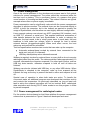
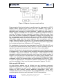
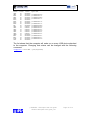
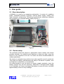
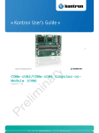
Radiological node μ-GaRaMo
(Description and user guide)
MEIS d.o.o.
Authors: Sašo Vrbinc, Darko Popović
Postal address: MEIS d.o.o., Šmarska 40, SI-1291 Škofljica, Slovenia
Email: [email protected], Web: www.meis.si
June 2012
EMPTY PAGE
μ-GaRaMo – Description and user guide
Garamo-description-user-guide_v01
Page 2 of 13
DOCUMENT: Garamo-description-user-guide_v01.doc
DOCUMENT HISTORY
VERSION
01
DESCRIPTION
Creation of the document, added content of
GaRaMo device.
DATE
14.06.2012
μ-GaRaMo – Description and user guide
Garamo-description-user-guide_v01
AUTHORS
Sašo Vrbinc,
Darko Popović
Page 3 of 13
EMPTY PAGE
μ-GaRaMo – Description and user guide
Garamo-description-user-guide_v01
Page 4 of 13
TABLE OF CONTENTS
1.
DESCRIPTION ................................................................................................................................ 7
1.1
POWER MANAGEMENT ................................................................................................................ 8
1.1.1
2.
Power management for radiological nodes ...................................................................... 8
USER GUIDE ................................................................................................................................ 11
2.1
SHORT DESCRIPTION ................................................................................................................. 11
2.2
DEVICE SETUP ........................................................................................................................... 11
2.3
BASIC OPERATION ..................................................................................................................... 12
2.4
USB KEY DATA TRANSFER ...................................................................................................... 12
2.5
TROUBLESHOOTING .................................................................................................................. 13
μ-GaRaMo – Description and user guide
Garamo-description-user-guide_v01
Page 5 of 13
EMPTY PAGE
μ-GaRaMo – Description and user guide
Garamo-description-user-guide_v01
Page 6 of 13
1. Description
µ-GaRaMo consists of a probe, embedded computer, battery, USB connector
and power supply. The embedded computer has following specs:
Intel D945GCLF2D mini-ITX Motherboard + integrated Intel Atom 330
2x 1.6Ghz
4x USB 2.0
VGA, Serial and Parallel
1024MB DDR2 667 RAM
2,5” 40GB SATA HDD
Radiological data are collected from the probe every half an hour using
gamma radiation measuring device. The acquisition takes approximately 10
seconds, afterwards the computer becomes idle. Therefore, ACPI (Advanced
Configuration and Power Interface) has to be configured to sleep(suspend)
the computer, and wakeup on every half an hour with help of an external timer
in order to conserve power, which is especially significant when running on
battery. Some reconsideration have been made regarding to put the computer
in hibernation, but then the ability to wakeup the computer with USB key is
lost.
Figure 1: μ-GaRaMo
μ-GaRaMo – Description and user guide
Garamo-description-user-guide_v01
Page 7 of 13
1.1 Power management
One of the crucial problems in the development process was to find optimal
solutions for power management. The power should be conserved while the
test bed runs on battery. This is necessary feature of µ-garamo that gives
users freedom of choosing test bed location. The outdoor locations are typical
example where often no power supply is available.
Power consumption can be significantly reduced with the power management
described in previous section. The external timer can be connected directly to
AC/DC to boot the computer, but in the testbed we wanted to simplify the
usage of SymbioNode, and therefore we used slightly different configuration.
Linux supports wakeup over almost any ACPI compliant HW interface, such
as USB, CF, ethernet or serial port. This enables additional automation of
data transfer between the host and SymbioNode. In order to wakeup the
computer, the host needs to be in ‘sleep’ power state. In such state, the host
hardware is held under low voltage, which is enough for host to detect
external devices (plugged/unplugged). When such event occurs, the host
wakes up and resumes the processes.
Test bed specification assumes two events that can wake up the computer:
Automatic wakeup/sleep invoked by external timer connected to the
serial port (only pin 9 is relevant).
USB key wakeup/sleep when inserted/removed
Wakeup is regularly invoked by external timer on every half an hour to acquire
radiological data from the probe. The data acquisition takes approximately 10
seconds, afterwards the computer suspends if no other task is active, such as
USB key data transfer, otherwise suspend is held off until all tasks are
finished.
Wakeup can also be initiated with USB key, or any other USB device. When
SymbioNode is attached to the computer, wake up from suspend will be
initiated. As long as the key is present the task is active and suspend is held
off.
Special case of operation is when both tasks are active. To handle the
concurrent tasks, an additional program was developed that monitors activity
and controls the suspension. As previously described, as long at least one
task is active the suspend procedure will not be invoked. Both, radiological
data acquisition and running PLUTI tasks needs to use this program in order
to prevent suspend.
1.1.1 Power management for radiological nodes
For the outdoor devices based on Intel Atom platform the power management
scheme that is presented on Figure 2 has been developed and used.
μ-GaRaMo – Description and user guide
Garamo-description-user-guide_v01
Page 8 of 13
Figure 2: Diagram of power supply wiring
Power supply of this kind of nodes is usually based on solar panel or AC/DC
adapter where standard 220V power lines are available. This power is
distributed to the PICO UPS uninterruptible power supply unit [10]. This unit
redirects power according to current conditions. If power from solar panel or
AC/DC adapter is available then the power is supplied to embedded computer
and the 12V battery is being charged if necessary. When the main input
power fails the power is supplied to embedded computer from the battery until
it is not drained or power is restored. Power from UPS is distributed also to
the programmable timer that drives the ignition input of the PICO PSU M3ATX power supply has three inputs (ground, 12V and ignition) and ATX
output. When the ignition is turned on (12V) the power supply activates power
on ATX connector. When the ignition is turned off (0V) the power supply waits
for 1 minute and then turns off power on ATX connector.
For signalization of power loss a special signal from PICO PSU M3-ATX unit
is used. One minute before the power will be cut off the operating system is
signalled through common power on/off signal line of the motherboard.
Arduino μ-Controller for advanced power management control has been used
as replacement of. It is an open-source electronics prototyping platform based
on flexible, easy-to-use hardware and software. It was needed for new
advanced controller because previously used timer had limited number of
ON/OFF time intervals and it oscilated when the power supply dropped under
11.5V. It is developed for all kind of nodes (Intel Embedded computers,
embedded routers) and programmable and configurable over RS232 or USB,
no need for special driver, development platform independed (for Windows
and Linux available). It has very low power consumption (approx. 10 mW)
Wake up with USB device
As noted before, wakeup can be initiated over any hardware component
supported by the ACPI. On regular computer or a laptop for example, power
button is configured to wake up the machine from sleep by default, but
support for other devices requires additional configuration. Every ACPI
compliant device has a wakeup status flag (enabled/disabled). The following
command prints all devices and their status for ACPI sleep activity:
μ-GaRaMo – Description and user guide
Garamo-description-user-guide_v01
Page 9 of 13
n4c@garamo:~> cat /proc/sleep
Device S-state
Status
Sysfs node
LANC
S5
disabled
HDEF
S4
disabled pci:0000:00:1b.0
RP02
S5
disabled pci:0000:00:1c.1
WNIC
S5
disabled pci:0000:03:00.0
RP03
S5
disabled pci:0000:00:1c.2
ECF0
S5
disabled
RP05
S5
disabled pci:0000:00:1c.4
ECF0
S5
disabled
RP06
S5
disabled pci:0000:00:1c.5
NIC
S5
disabled pci:0000:86:00.0
USB1
S3
enabled
pci:0000:00:1d.0
USB2
S3
enabled
pci:0000:00:1d.1
USB3
S3
enabled
pci:0000:00:1d.2
USB4
S3
enabled
pci:0000:00:1a.0
USB5
S3
enabled
pci:0000:00:1a.1
USB6
S3
enabled
pci:0000:00:1a.2
U6RM
S3
disabled
EHC1
S3
disabled pci:0000:00:1d.7
EHC2
S3
disabled pci:0000:00:1a.7
PCIB
S5
disabled pci:0000:00:1e.0
HST1
S5
disabled
The list shows that the computer will wake up on every USB device attached
to the computer. Changing their status can be changed with the following
command:
root@garamo:/ # echo USB1 > /proc/acpi/sleep
μ-GaRaMo – Description and user guide
Garamo-description-user-guide_v01
Page 10 of 13
2. User guide
2.1 Short description
μ-GaRaMo is a device for measuring radioactivity. It consist of a radiation
probe, embedded personal computer, external power supply, battery and
other electronic components. Everything is packed into aluminium briefcase
with exception of an external power supply (Figure 1).
Figure 1
2.2 Device setup
The briefcase should be placed in appropriate indoor location with lowest
possible humidity. You should avoid exposure to direct sun light, since the
device is very sensitive to the sun. As noted, the device is not suitable for
outdoor placement.
The device is activated every half an hour when specific sound is produced.
This might be irritating, and therefore the setup of the device in places, such
as living room or bedroom, is not advisable.
It's recommended to run the device on power supply constantly, since the
battery ensures only 40 hour autonomy. Otherwise, If constant power supply
is not available, you have to recharge the battery on every 24 hours, and wait
approximately 2 hours to fully recharge.
μ-GaRaMo – Description and user guide
Garamo-description-user-guide_v01
Page 11 of 13
2.3 Basic operation
The device operation is completely automatic and therefore no manual
switching of power on/off is required. Connect the power supply to AC power
outlet (230V), afterwards attach the circular plug on the other side of the
device (the plug is located on the briefcase - Figure 2). From this point the
device operation is automatic.
Figure 2
2.4 USB Key Data Transfer
Use an appropriate USB key for successful data transfer. The procedure is as
follows:
1. Insert the key in the USB slot attached to the cable(Figure 3).
Afterwards, the computer will wakeup and start with automatic data
transfer.
Figure 3
2. Wait for at least six minutes before you remove the key. Therefore, you
assure successful data transfer and device stability.
μ-GaRaMo – Description and user guide
Garamo-description-user-guide_v01
Page 12 of 13
3. After fix minutes, you can safely remove the key.
2.5 Troubleshooting
If the device is not responding on USB key insertion, you need to reinsert it. If
the trouble persist make sure the device is connected to the external power
supply (power supply connected on 230V and correctly plugged in).
Another possible reason for misoperation is depleted or discharged battery. In
this case, the following procedure should be taken:
1. Open the briefcase
2. Unplug the wire or clamp on the battery (Figure 4)
Figure 4
3. Connect the device to power supply (Figure 2)
4. Attach the wire back to its place, where it was unplugged.
5. Close the briefcase
μ-GaRaMo – Description and user guide
Garamo-description-user-guide_v01
Page 13 of 13