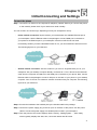
1
Desktop SIP IP Phone VIP-251T User’s manual Version 1.0 1 Copyright Copyright (C) 2011 PLANET Technology Corp. All rights reserved. The products and programs described in this User’s Manual are licensed products of PLANET Technology, This User’s Manual contains proprietary information protected by copyright, and this User’s Manual and all accompanying hardware, software, and documentation are copyrighted. No part of this User’s Manual may be copied, photocopied, reproduced, translated, or reduced to any electronic medium or machine-readable form by any means by electronic or mechanical. Including photocopying, recording, or information storage and retrieval systems, for any purpose other than the purchaser's personal use, and without the prior express written permission of PLANET Technology. Disclaimer PLANET Technology does not warrant that the hardware will work properly in all environments and applications, and makes no warranty and representation, either implied or expressed, with respect to the quality, performance, merchantability, or fitness for a particular purpose. PLANET has made every effort to ensure that this User’s Manual is accurate; PLANET disclaims liability for any inaccuracies or omissions that may have occurred. Information in this User’s Manual is subject to change without notice and does not represent a commitment on the part of PLANET. PLANET assumes no responsibility for any inaccuracies that may be contained in this User’s Manual. PLANET makes no commitment to update or keep current the information in this User’s Manual, and reserves the right to make improvements to this User’s Manual and/or to the products described in this User’s Manual, at any time without notice. If you find information in this manual that is incorrect, misleading, or incomplete, we would appreciate your comments and suggestions. CE mark Warning The is a class B device, In a domestic environment, this product may cause radio interference, in which case the user may be required to take adequate measures. WEEE Warning To avoid the potential effects on the environment and human health as a result of the presence of hazardous substances in electrical and electronic equipment, end users of electrical and electronic equipment should understand the meaning of the crossed-out wheeled bin symbol. Do not dispose of WEEE as unsorted municipal waste and have to collect such WEEE separately. Trademarks The PLANET logo is a trademark of PLANET Technology. This documentation may refer to numerous hardware and software products by their trade names. In most, if not all cases, their respective companies claim these designations as trademarks or registered trademarks. 2 Revision User’s Manual for PLANET SIP IP Phone: Model: VIP-251T Rev: 1.0 (2011, January) Part No. EM-VIP251TV1.0 3 TABLE OF CONTENTS Chapter 1 Introduction .......................................................................... 7 Overview............................................................................................................................7 Package Content ...............................................................................................................8 Physical Details .................................................................................................................8 Front View and Keypad function................................................................................8 Rear View .................................................................................................................10 Get Familiar with LCD.............................................................................................10 Chapter 2 Preparations & Installation ................................................ 12 Physical Installation Requirement ................................................................................12 Administration Interface ...............................................................................................14 Web configuration access: ........................................................................................14 Chapter 3 Network Service Configurations....................................... 15 Configuring and monitoring your IP Phone from web browser ................................15 Overview on the web interface of IP Phone .............................................................15 Manipulation of IP Phone via web browser .............................................................15 WAN IP address configuration via web configuration interface ..............................16 Chapter 4 Configuration From Button ............................................... 18 Information .....................................................................................................................18 Menu Item Introduction............................................................................................18 How to configurate from Menu ................................................................................19 View Phone IP and Number .....................................................................................20 Chapter 5 Initial Connecting and Settings ........................................ 21 Connect the phone ....................................................................................................21 Initial Setting ............................................................................................................22 Static mode ...............................................................................................................22 DHCP mode..............................................................................................................22 PPPoE mode .............................................................................................................22 Chapter 6 Calls..................................................................................... 24 Make Phone Calls.....................................................................................................24 Answer Calls ............................................................................................................25 Call Log ....................................................................................................................25 Short message (SMS) ...............................................................................................26 Volume Settings........................................................................................................26 Mute when making a call .........................................................................................26 Call Hold ..................................................................................................................26 Call Waiting ..............................................................................................................26 Call Transfer .............................................................................................................26 4 Three Way Conference .............................................................................................27 Chapter 7 Configuration from WEB ................................................... 28 System Status............................................................................................................28 Network Configuration.............................................................................................28 WAN settings............................................................................................................28 LAN settings.............................................................................................................30 DHCP Server settings ...............................................................................................30 MAC Clone settings .................................................................................................31 VPN settings .............................................................................................................32 SIP Protocol Settings_SIP-1 Setting.........................................................................33 Supplement Service Settings ....................................................................................34 Media Settings ..........................................................................................................35 Other Settings ...........................................................................................................36 General Settings........................................................................................................37 Advanced Settings_QoS Settings .............................................................................37 Dial Rule...................................................................................................................38 Other Settings ...........................................................................................................41 Equipment Manage_ Device Manage ......................................................................41 Upgrade Software .....................................................................................................42 Volume Settings........................................................................................................43 SNMP .......................................................................................................................43 TR-069 Settings........................................................................................................43 Provision...................................................................................................................44 Cert Management .....................................................................................................46 Phonebook ................................................................................................................46 User Manage.............................................................................................................46 System Log ...............................................................................................................47 Reboot.......................................................................................................................47 Relogin .....................................................................................................................48 Chapter 8 Provision Testing ............................................................... 49 TFTP testing .............................................................................................................49 HTTP testing.............................................................................................................49 HTTP Server.............................................................................................................50 HTTPS server ...........................................................................................................51 HTTP testing.............................................................................................................52 HTTPS testing ..........................................................................................................52 Appendix A Voice communications...............................................................................53 Case 1: Voice communication via SIP IP PBX _IPX-300 ........................................53 Case 2: Call Forward Feature_IP to IP Forward.......................................................54 Appendix B The method of operation guide ................................................................56 5 Call Transfer .............................................................................................................56 3-Way Conference ....................................................................................................56 Call Waiting ..............................................................................................................56 Appendix C VIP-251T Specifications ...........................................................................57 6 Chapter 1 Introduction 1 Overview PLANET continues to bring innovation to the Voice over IP communications market with cutting edge products and Internet telephony manufacturing experience. For a cost-effective and high performance VoIP communications today, PLANET introduces the desktop SIP IP Phone, VIP-251T, to fulfill the VoIP deployment needs from ITSP, enterprises to home. The VIP-251T features high-quality speakerphone technology and provide various voice services including speaker on / off, call hold and call transfer with user-friendly speed dial button design. it also has additional features such as built-in DHCP clients, password-protected machine management, LCD menu display, speed-dial keys, last number redial, incoming message indicator and user-intuitive web administration system. The VIP-251T brings the benefits of VoIP technologies to your daily life. It is the SIP IP phone featuring self-contained, service-integrated, intelligent phone functions, and powerful voice processing. The VIP-251T can effortlessly deliver toll voice quality equivalent to the regular SIP protocol connections by utilizing cutting-edge Quality of Service, echo cancellation, comfort noise generation (CNG) and voice compensation technology. Meanwhile, the dual Ethernet interfaces on the IP Phone allow users to install it in an existing network without interfering with desktop PC network connections. The VIP-251T is an ideal solution for office / home use as well as for Internet Telephony Service Provider (ITSP). Product Features • SIP 2.0 (RFC3261) compliant • G.711A, G.711U and G.729 voice codec • Supports STUN, Outbound Proxy • Supports up to 2 Proxy server registrations • 3-Way Conference / Caller ID • Built-in phone book • Call Hold / Waiting / Transfer / Forward • VAD / CNG / AEC / PLC / AJB /AGC • Incoming / Outgoing / Miss Call record • QoS / NAT / DHCP Server • Auto-Provisioning / TR-069 • Web / Keypad management 7 Package Content The contents of your product should contain the following items: VoIP IP Phone Power adapter Quick Installation Guide User’s Manual CD RJ-45 cable x 1 Physical Details The following figure illustrates the front/rear panel of IP Phone. Front View and Keypad function Front Panel of VIP-251T 8 Keypad Description 1 LCD Display Menu and all status shall be displayed for users. 2 Phone Book Enter the phone book selection. 3 Call Log 4 MSG 5 Pick Up 6 Delete 7 Mute 8 3 Way Call 9 Transfer 10 DND 11 * 12 # (Send) 13 Hold 14 Redial 15 Menu To bring out the menu selection while IP Phone is in idle state. 16 Enter To be used as confirm configuration or enter sub-menu. 17 Cancel 18 Line Switch 19 Vol △/ Vol ▽ 20 Hand Free Enter the call log menu, including Incoming, Outgoing, Missed three selections. Enter the short message mode To pick up other ringing phone call in same LAN (SIP-1 supported, SIP-2 unsupported) Delete a character when in text editing mod Press this key when in conversation, you can hear the other side, and the other side can not hear you. Press this button can make conference function. To transfer an active call (incoming call answered or outgoing call accepted) to another devices. Enable/Disable the DND function. “*” is used as “.” when making a Direct IP call. End dialing when you dial the number To hold the conversation. Press to dial the last dialed number when the IP Phone is off-hooked. Press Cancel to back to up-level menu. Hanging on or pick up headset, pressing to switching between Line 1 and Line 2. To move the sub-menu selection, or adjust the volume. To switch between the usage of the handset and the speaker devices. 9 Rear View Rear Panel of VIP-251T 1 DC 5V 2 WAN 3 LAN LNote 5V DC Power input outlet RJ-45 connector, for Internet access, connected directly to Switch/Hub through straight CAT-5 cable. RJ-45 connector, to maintain the existing network structure, connected directly to the PC through straight CAT-5 cable Use only the power adapter shipped with the unit to ensure correct functionality Get Familiar with LCD Display of the LCD 1 The center of the LCD displays the day, the date and the time The left bottom of the LCD displays the Display Name set in the configuration. 2 3 This icon displays the WAN Network Status. It indicates the physical WAN network is connected. This icon displays the WAN Network Status. It indicates the physical WAN network is unconnected. 10 4 5 6 7 This icon displays the LAN Network Status. It indicates the physical LAN network is connected. This icon displays the LAN Network Status. It indicates the physical LAN network is unconnected. The icon displays the register Status. It indicates the phone is registered. The icon displays the register Status. It indicates the phone is unregistered. The icon shows new SMS. 8 If short massage exists and still unreaded, the icon appears. If no short massage, this icon disappears and this area is empty. 11 Chapter 2 Preparations & Installation 2 Physical Installation Requirement Step 1: Handset Connection Plug Handset Core with Handset and Handset Jack. Step 2: Connecting Power Adapter and Network ÍNote Use only the power adapter shipped with the unit to ensure correct functionality. 12 Step 3: Computer Network Cable Plug RJ-45 Cable with WAN port and Switch/Hub Step 4: Computer Network Setup Plug RJ-45 Cable with LAN port and Computer Step 5: Login Prompt Set your computer’s IP address to 192.168.0.x, where x is a number between 2 to 254 (except 1 where is being used for the IP Phone by default). If you don’t know how to do this, please ask your network administrator.Use web browser (Internet Explorer 6.0 or above) to connect to 192.168.0.1 (type this address in the address bar of web browser). You’ll be prompted to input password: admin 13 Administration Interface The IP Phone provides GUI (Web based, Graphical User Interface) for machine management and administration. Key pad administration also available for simple configuration. Web configuration access: To start IP Phone web configuration, you must have one of these web browsers installed on computer for management • Microsoft Internet Explorer 6.0.0 or higher with Java support Default IP address of IP Phone is 192.168.0.1. You may now open your web browser, and insert http://192.168.0.1 in the address bar of your web browser to logon IP Phone web configuration page. IP Phone will prompt for logon password, please enter: admin to continue machine administration. ÍNote In order to connect machine for administration, please locate your PC in the same network segment (192.168.0.x) of IP Phone. If you’re not familiar with TCP/IP, please refer to related chapter on user’s manual CD or consult your network administrator for proper network configurations. 14 Chapter 3 Network Service Configurations 3 Configuring and monitoring your IP Phone from web browser The IP Phone integrates a web-based graphical user interface that can cover most configurations and machine status monitoring. Via standard, web browser, you can configure and check machine status from anywhere around the world. Overview on the web interface of IP Phone With web graphical user interface, you may have: More comprehensive setting feels than traditional command line interface. Provides user input data fields, check boxes, and for changing machine configuration settings Displays machine running configuration To start IP Phone web configuration, you must have one of these web browsers installed on computer for management Microsoft Internet Explorer 6.0.0 or higher with Java support Manipulation of IP Phone via web browser Log on IP Phone via web browser After TCP/IP configurations on your PC, you may now open your web browser, and input http://192.168.0.1 to logon IP Phone web configuration page. IP Phone will prompt for logon password: admin IP Phone log in page When users login the web page, users can see the IP Phone system information like firmware version, company…etc in this main page. 15 IP Phone main page WAN IP address configuration via web configuration interface Execute your web browser, and insert the IP address (default: 192.168.0.1) of VIP in the address bar. After logging on machine with password (default: admin), browse to “Network Configuration” --> “WAN” configuration menu: Parameter Description IP address WAN IP address of IP Phone Default: 192.168.0.1 Subnet Mask WAN mask of IP Phone 16 Default: 255.255.255.0 Default Gateway Gateway of IP Phone Default: 192.168.0.254 After confirming the modification you’ve done, Please click on the Submit button to apply settings and browse to “Save & Reboot” menu to reboot the machine to make the settings effective. Connection Type Data required. In most circumstances, it is no need to configure the DHCP Fixed IP settings. DHCP client The ISP will assign IP Address, and related information. The ISP will assign PPPoE username / password for Internet PPPoE L Hint access, Please consult your ISP personnel to obtain proper PPPoE/IP address related information, and input carefully. If Internet connection cannot be established, please check the physical connection or contact the ISP service staff for support information. Save Modification to Flash Memory Most of the IP Phone parameters will take effective after you modify, but it is just temporary stored on RAM only, it will disappear after your reboot or power off the IP PHone, to save the parameters into Flash ROM and let it take effective forever, please remember to press the Save & Reboot button after you modify the parameters. 17 Chapter 4 Configuration From Button 4 Information You can browse and modify the phone’s IP address, ringing, software information, default settings and reboot and so on. Menu Item Introduction The below table list Menu items which VIP-251T included: Main menu Menu Item (LCD display) Submenu Items(LCD display) 1.1. SEND 1. TEXT MESSAGE 1.2. RECEIVED BOX 1.3. SENT BOX 2. QUICK CONFIG 2.1. Account 3.1.1. STATIC 3.1. LAN 3.1.2. DYNAMIC 3.1.3. PPPoE 3. NETWORK 3.2. NAT 3.3. STUN 4.1. SIP ACCOUNT 3.2.1. ENABLE 3.2.2. DISABLE 3.3.1. ENABLE 3.3.2. DISABLE 4.1.1. PESSWORD 4.1.2. ACCOUNT (The MAX length is 19) 4.1.3. DISPLAY (The MAX length is 19) 4.1.4. MY TEL NIMBER 4. ACCOUNT (default password:0000) (The MAX length is 19) 4.2. SERVER 4.2.1. SIP DOMAIN 4.2.2. SIP PROXY 4.2.3. SIP SBC SERVER 4.2.4. SMS DOMAIN 4.2.5. SMS PROXY 4.2.6. SMS SBC SERVER 5. SERVICE 5.1. LANGAUGE 5.1.1. ENGLISH 18 5.1.2. BELLTYPE LIST 1~N 5.1.3. ENABLE or DISABLE 5.2. BELL TYPE 5.3. CALL WAITING 5.4. AUTO AREACODE 5.5. CALL FORWARD 5.6. HOTLINE 5.7. ALARM 5.8. LOCAL TIME 6.1. DOMAIN MODE 6. ADVANCE 6.2. CARRY PORT INFO 6.3. SIP PORT 7.1. SET DEFAULT 7.2. SW UPGRADE 7.3. HANGE PWD 7. MANAGE 7.4. SET BACKLIGHT 7.5. SET CONTRAST 7.6. WEN LOGIN 7.7. WEB PORT 8. STATUS 9. REBOOT How to configurate from Menu 1. When the phone is on-hook, press the “MENU” button to enter Main menu. 2. Press the “UP/VOL+” or “DOWN/VOL-" buttons to browse Menu Items. 3. Press the “ENTER” button to enter the submenu of the right item, and you can see the changed value in the LCD. 4. Press the “UP/VOL+” or “DOWN/VOL-" buttons to select Submenu Items you need to set, and you can also select it with the corresponding digit buttons in the buttonboard. 5. Press the “ENTER” to confirm and save. Note: User can give up modification and go back to up level Menu by pressing “CANCEL” button. For example: A. Set IP address: 1. When the phone is on-hook, press the “MENU” button to enter main menu. 2. Press the “DOWN/VOL-" button to get the selection on the NETWORK item. 3. Press the “ENTER” button to enter the submenu and press the ” DOWN/VOL-” to get the selection on LAN, then press “ENTER” button to enter configuration and you can see the 19 current setting value in the LCD. 4. Press the digit buttons to input 192.168.1.1 to set the IP address. Here press the button “*” to input the character “.”. 5. Press the “ENTER” to confirm and save. B. Set Ringing: 1. When the phone is on-hook, press the “MENU” Button to enter main menu. 2. Press the “DOWN/VOL-" button to select the SERVICE item. 3. Press the “ENTER” button to enter the submenu and then press the button “DOWN/VOL-" to select the BELLTYPE item, press “ENTER” to enter the configuration. 4. Press the “UP/VOL+” to select the RING you want. 5. Press the “ENTER” to confirm and save. View Phone IP and Number When the phone is on-hook, press the “MENU” button, and then press the “DOWN/VOL-“ to select the “STATUS” item and press “ENTER” button to enter the system state page, IP Phone’s LCD will display the information as follows: S/W Ver. Subnet Mask 111 255.255.255.0 H/W Ver. Gateway Address 101 192.168.20.1 DSP Ver. DNS Server1 D2.52 164.124.101.2 Product No. DNS Server2 VIP-251T 172.20.106.5 Network Mode MAC Address STATIC 00:21:f2:01:07:82 IP Address Phone Number 192.168.20.13 3333 You can press “DOWN/VOL-“ or “UP/VOL+“ button to browse all these lines. 20 Chapter 5 Initial Connecting and Settings 5 Connect the phone Step 1: Connect the IP Phone to the corporate IP telephony network. Before you connect the phone to the network, please check if your network can work normally. You can do this in one of two ways, depending on how your workspace is set up. - Direct network connection: By this method, you need at least one available Ethernet port in your workspace. Use the Ethernet cable in the package to connect WAN port on the back of your phone to the Ethernet port in your workspace. Since this VoIP Phone has router functionality, whether you have a broadband router or not, you can make direct network connect. The following figure is for your reference. - Shared network connection: Use this method if you have a single Ethernet port in your workspace with your desktop computer already connected to it. First, disconnect the Ethernet cable from the computer and attach it to the WAN port on the back of your phone. Next, use the Ethernet cable in the package to connect LAN port on the back of your phone to your desktop computer. Your IP Phone now shares a network connection with your computer. The following figure is for your reference. Step 2: Connect the handset to the handset port by the handset cable in the package. Step 3: Connect the power supply plug to the DC port on the back of the phone. Use the power cable to connect the power supply to a standard power outlet in your workspace. Step 4: Then the phone’s LCD screen displays “Hello...booting....loading system....”, when ready screen typically displays the date, time, connection status and SIP name. 21 Initial Setting This VoIP Phone provides you with rich function and parameters setting. If you have enough knowledge about network and SIP protocol, it is better for you to understand many parameters. But if you know little about network and SIP protocol, you can also easily make initial setting according to the following steps to enjoy rapidly high quality voice and low cost from this VoIP Phone. Before make initial setting, please check if your corporate IP telephony network can work normally, and you have finished “connect the phone”. Static mode This VoIP Phone provides you with rich function and parameters setting. If you have enough knowledge about network and SIP protocol, it is better for you to understand many parameters. But 1. Prepare the network’s parameters first. IP Address,Netmask, Default Gateway and DNS server IP address are needed. Please contact the service provider or technician of network.for above information. 2. Pressing [MENU] button,and press the button to browse “ Network”. Then press the Enter button, the LCD screen will display “WAN” 3. Press the Enter button, and press the button to browse “STATIC”. 4. Pressing Enter button, the LCD screen will display IP Address, press 0~9 digit buttons and * (used as “.”) to enter IP Address,and user can press Delete to delete old parameter. 5. Press Enter button, the LCD screen will display Subnet Mask. 6. Press Enter button to show Gateway. Input your gateway . 7. Press Enter button to show 1st DNS. Input your DNS server address 8. Press Enter button to show 2st DNS. Input your DNS server address 9. When you finished, press enter to save the settings, then IP Phone will reboot automatically. DHCP mode This VoIP Phone Supports DHCP by default. It will receive an IP address and other network-related settings (Netmask, IP gateway, DNS server) from the DHCP server. If your network supports DHCP, you can connect this VoIP Phone directly to the network. If your network doesn’t support DHCP, you need change this VoIP Phone’s network connection setting. According to the following steps, change this VoIP Phone’s DHCP network connection setting into PPPoE or static IP which your network supports at present. PPPoE mode 1. Please prepare PPPoE ID and PPPoE password 2. Press the [MENU] button, and press the button to browse “ Network”. Then press the 22 (Enter) button, the LCD screen will display “WAN”. 3. Press the Enter button, and press the button to browse “PPPoE”. 4. Press the Enter button, the LCD screen will display PPPoE ID, press 0~9 digit buttons to enter ID, press Delete button to delete one digit once a time, press Cancel button to previous menu. 5. After you finished, press Enter button to set PPPoE password (which will replaced by *). 6. When you finished, press enter to save the settings, then IP Phone will reboot automatically. 23 Chapter 6 Calls 6 Make Phone Calls Items Descriptions 1. Pick up Handset or press [SPEAKER] button, you will hear the dialing tone (busy tone if not register successfully), LCD will display “>” 2. Enter the phone numbers, wait for 4 seconds or press”#” or “REDIAL” Dial directly button to make a call. 3. Press PickUp button to make a call. Note: If user input a wrong number, make the phone on-hook and then off-hook, input the numbers again. Or you can press the “Delete” button to delete it. 1. Open SIP Protocol Settings→Supplement Service page, enable PickUp PickUp call and set PickUp Feature Code which is a phone number, . 2. When IP Phone in idle status, press PickUp button to call the phone number. 1. Pick up Handset or press [SPEAKER] you will hear the dialing tone (busy tone if not register successfully), LCD will display “>” 2. When the phone is Off-hook, press “REDIAL” button to redial the number last called. 3. Once pressed, the last dialed number will be displayed on the LCD the corresponding DTMF tones are played out and an outgoing call is sent. Re-dial Or 1. In idle status, press Redial button to redial the number which last called.directly 2. Once pressed, the last dialed number will be displayed on the LCD the corresponding DTMF tones are played out and an outgoing call is sent Browse the 1. When the phone is On-hook, press the “Call log” button and select the incoming records “INCOMING” item and use UP or DOWE button to browse the Incoming and dial Records. 2. Once the desired number is identified and displayed on the LCD screen, press the “#” button and a new call will be sent out immediately. Browse the outgoing records and dial 1. When the phone is On-hook, press the “Call log” button and select the “OUTGOING” item to browse the Outgoing Records. 2. Once the desired number is identified and displayed on the LCD screen, press the “#” button and a new call will be sent out immediately 24 1. Pick up Handset or press [SPEAKER], LCD will display “>”. 2. Input IP with digits, and then press “#” button to send the number. Note: 1. After IP Phone registered with SIP Server / IP PBX successfully, the IP Phone just could make peer-to-peer call. 2. The ways for inputting IP with digits as followings: Input “*” instead of “.”, “**” instead of “@”. IP peer-to-peer dial 3. When user dials IP peer-to-peer call, user can dial IP address only, also can add phone number or server port information. 4. You can use IP Dial at any time. Below are 4 examples: IP address E.g.: 192*168*100*234 IP address*port E.g.: 192*168*100*234*5061 Phone Number**IP address E.g.: 1002**192*168*100*234 Phone Number**IP address*port E.g.: 1002**192*168*100*234*5061 Answer Calls 1. Answer an Incoming Call when the Phone is on-hook When the phone is on-hook, there is an incoming call; LCD will display the number of incoming call. Pick up the handset or press [SPEAKER] to answer the call. 2. Answer an Incoming Call when the Phone is making a call There will be a “du du ~ ~” call waiting tone to prompt you that there is a new incoming call when the Phone is making a call. Press the “HOLD” button to answer the new incoming call, when the call is over, press the “HOLD” button again to switch to the previous call. Call Log 1. View Incoming Call Press “Call Log” button and select the “Incoming call” item to browse the last 20 Incoming Call when the phone is on-hook. 2. View Outgoing Call Press “Call Log” button and select the “Outgoing call” item to browse the last 20 outgoing call when the phone is on-hook. 25 Short message (SMS) When the phone is on-hook, press “SMS” button to get the short massage service function(if the SIP-2 account is registered), then you can select “SEND” item to enter the short message editing mode, or select “RECEIVED BOX” item to browse the already received short messages, also you can select “SENT BOX” to view the messages sent before. Volume Settings When the phone is on-hook, press “UP/+” to increase ring volume and press “DOWN/-“ to decrease ring volume. LCD will display the corresponding grade. When the phone is off-hook, press “UP/+” to increase Handset volume and press the “DOWN/-“ to decrease Handset volume. LCD will display the corresponding grade. When the phone is in the hands-free mode, press “UP/+” to increase Speakerphone volume and press “DOWN/-“ to decrease Speakerphone volume. LCD will display the corresponding grade. Mute when making a call Presses “MUTE” to mute when making a call, press it again to resume MIC. Call Hold While in conversation, pressing the “Hold” button will put the remote end on hold. Pressing the “Hold” button again will release the previously Hold state and resume the bi-directional media. Call Waiting If call waiting feature is enabled (by default), while the user is in a conversation, he will hear a special stutter tone if there is another incoming call. User then can press “HOLD” button to put the current call party on hold automatically and switch to the other call. Pressing “HOLD” button toggles between two active calls. Call Transfer IP Phone supports blind transfer and attended transfer. - Blind Transfer: User can transfer an active call to a third party without announcement. At first, A talk with B. 1. A press “Transfer” button to hold B, A will hear dialing tone and input C phone number, end with “#” 26 2. Then B rings C, A and B will listen right-back tone. 3. If C answer the call, A will hook on. 4. If C does not answer the call successfully, A will talk with B again. - Attended Transfer: User can transfer an active call to a third party with announcement. At first, A talk with B. 1. A press “HOLD” button to hold B, A will hear dialing tone and input C phone number, end with “#”. 2. Then A rings C; if C answer the call. A will talk with C firstly 3. If C LANts to talk with B, A press “TRANSFER” button to transfer, At the same time, A hook on.. 4. If B do not talk with C successfully, A will talk with B again. LNote A should not hook on quickly, in order that A can talk with B if B do not talk with C successfully. Three Way Conference 1. Assuming that call party A and B are in conversation. A LANts to bring C in a conference 2. Party A presses the “HOLD” button and put the party B on hold. At this time, party A will hear a dial tone again. 3. A dials C’s number to make the call, If C answers the call, then A presses “CONFERENCE” button to bring B, C in the conference. 4. If C does not answer the call, A can press “HOLD” back to talk to B 5. During the conference, if B or C drops the call, the remaining two parties can still talk. However, if A the conference initiator hangs up, all calls will be terminated. 27 Chapter 7 Configuration from WEB 7 System Status User can see the System Status page if you login the Web successfully. And you can also click [System Status] to enter this page. The page displays IP Phone’s current status, including current software version, LAN configuration, and register status and so on. If you enable the VPN, it also displays the dummy IP. Network Configuration You can click the [Network Configuration] to login the Network Configuration page. You can set Network parameters including LAN, PC, DMZ, DHCP Server, MAC Clone, VPN settings in this page. WAN settings The Web Server default port for is 80, the port can be changed via Web in Equipment Manage/Device Manage page Web Login Port table. Items Descriptions Web Interface Static 1. Set “Static” in the “IP Mode” text. 2. Set IP address, the IP address is the one of the local area Settings Introduction network. 3. Set Subnet Mask, it is usually “255.255.255.0” for the local area network. 4. Set Gateway, you can get it from your Administrator. 5. Set DNS, you can get it from your Administrator. 28 Web Interface DHCP 1. Set “DHCP” in the “IP Mode” text. 2. You should set “manual” in the “DNS Mode” if you set “DNS” Settings Introduction by yourself. And then fill the DNS in the two following texts. Generally speaking, you can set “Automatic” in the “DNS Mode” and IP Phone will get “DNS” from DHCP Server automatically. PPPoE Web Interface 1. Set “PPPoE” in the “IP Mode” text. 2. Fill the PPPoE account and password in the texts. 3. Enable the “PPPoE Auto-Dial”. You can also disable the “PPPoE Auto-Dial” if you click the “PPPoE Dial” manually for dialing the number. 4. You should set “manual” in the “DNS Mode” if you set “DNS” Settings Introduction by yourself. And then fill the DNS in the two following texts. Generally speaking, you can set “Automatic” in the “DNS Mode” and IP Phone will get “DNS” from DHCP Server automatically. 5. You should click the “Reboot” in the left of the page to reboot the IP Phone if you see the words “Please REBOOT to make the changes effective!” After Reboot, you can see PPPoE Status successful and the network parameters in the System Status page if IP Phone dial the number successfully. 29 Generally speaking, you should select a kind of IP Mode from the two IP Modes if you use IP Phone in the local area network. You can select the “Static” IP Mode if you are familiar with the Network Configuration and you can fill all the parameters in the texts by yourself. You can also select the “DHCP” IP Mode and let IP Phone get all the parameters from the DHCP Server. You can ask Administrator if you are still not clear. LAN settings The way of Data packages from WAN port to LAN port. There are three ways for Retransmits Mode: NAT, Bridge and disable. Disable: not retransmit. NAT Mode: retransmit by NAT Bridge Mode: retransmit by SWITCH. LAN IP and LAN Subnet Mask It is efficient if you select “NAT” for Retransmits Mode. You should set LAN IP and LAN Subnet Mask, generally specking, you can use the default values. You should select “NAT” or “Bridge” Mode if you connect your PC with IP Phone’s LAN port. It is suggested that you should use “NAT” Mode. Your PC’s Gateway address is same to IP Phone’s LAN and your PC’s IP address is the same to the network segment of IP Phone’s. (As the above page, your PC’s IP address should set 192.168.252.xxx), now your PC can connect to Internet. Probably, you can also use DHCP Server expediently. You can see the DHCP Server introductions in the following chapter. DHCP Server settings DHCP Server is another kind of Network function. IP Phone can supply DHCP service for the network which is linked with IP Phone’s LAN if you enable the DHCP Server of IP Phone’s LAN (Default setting is disable) 30 Items Descriptions Enable DHCP Server You can use DHCP Server if you enable it. DHCP Start Address DHCP Server Start Address. The Network Sect of DHCP Server Start Address should be the same with the one that IP Phone’s LAN. Generally speaking, you can use the default setting. DHCP Server End Address The Network Sect of DHCP Server End DHCP End Address Address should be the same with the one that IP Phone’s LAN. Generally speaking, you can use the default setting. Primary DNS Primary DNS that DHCP Server will distribute. You can use the default setting. Secondary DNS Secondary DNS that DHCP Server will distribute. You can use the default setting. Lease Time DHCP Server Leave Time. DHCP will send request to continue in period of validity. Unit is hour. You can use the default setting. You can use the default settings if you do not know the settings of DHCP Server well. You only need to enable the DHCP Server. After enabling the DHCP Server, your PC can link to Internet if you link your PC to IP Phone’s LAN and set your PC get IP automatically. MAC Clone settings MAC is the hardware address of network equipment. Sometimes, network providers may bind network account with the network equipment’s MAC address. So you may not pass the provider’s authentication when you use a new IP Phone. In this case, you can use MAC Clone to copy your PC’s MAC address to IP Phone’s WAN. MAC is an important parameter for network equipments, so you should make sure that the MAC is right, in order to prevent to make IP350 unusual. You can login IP Phone’s Web via WAN if you are incautious to make it wrong. And then clone the right MAC or resume the default settings. 31 1. You can see your PC’s MAC address in the “Current PC MAC Address” text. 2. It will copy “Current PC MAC Address” to “Cloned MAC Address” text if you click “Clone address” button. 3. Click the “save” button, and then click the “reboot”, if you login again you will see the IP Phone’s WAN MAC Address has changed. 4. Click “Cancel clone” button if you LANt to cancel the MAC Clone. You should save and reboot, and then it will be effective. VPN settings The IP Phone supports the PPTP and L2TP standard VPN protocol. Items Descriptions Enable VPN There are three options: Diable, PPTP, L2TP Initial Service IP The VPN Server address or domain name. Initial Service Port The VPN Server’s service port. Router Strategy Two options: Sip Only, ALL. - Sip Only : means only sip message will go though VPN channel by default, Other packet will router to LAN interface. however you can set some static routes to VPN interface using following Router Config. - ALL: all packets except to VPN server will go though VPN channel, and Router Config takes no effect. 32 Router Config Secondary DNS that DHCP Server will distribute. You can use the default setting. This parameter set a static route to VPN channel. The static route can be a single host route or a network route according to “Type”. Lease Time For example: route add -net 211.93.137.44 netmask 255.255.255.255 dev netb route add -net 220.201.0.0 netmask 255.255.0.0 dev netb route add -net 220.203.0.0 netmask 255.255.0.0 dev netb When you set Router Config, you should add the item one by one and click [Save] every time. You can see the router information in the same page. SIP Protocol Settings_SIP-1 Setting Protocol Settings include two line SIP accounts settings and general settings, including advanced and detail settings about Protocol. Items Descriptions If or not enable peer to peer. Peer To Peer - If enable, SIP-1 will not send register request to SIP server - In System Status, SIP-1 Status is Registered - SIP-1 can make call out, but others can not call SIP-1. Proxy DNS Type Choose the proxy DNS type from A Type and DNS SRV. 33 Domain name The domain name of SIP Server IP SIP Proxy The IP address SIP Server IP The port of SIP Server for service of VOIP by Providers, default is 5060. SIP Proxy Port You should enable “Carry Port Information” in the Other Settings page if the SIP Server Port is not 5060 or SIP messages need to carry port information for IP. Outbound Proxy Outbound Proxy Port Outbound Proxy ip or domain name. Outbound Proxy’s Service port. Phone Number Number of telephone provided by SIP Proxy. Account Account of telephone provided by SIP Proxy. Password Password of telephone provided by SIP Proxy. Display Name The display name when the IP phone is on-hook. Supplement Service Settings You can click the [Network Configuration] to login the Network Configuration page. You can set Network parameters including LAN, PC, DMZ, DHCP Server, MAC Clone, VPN settings in this page. Items Descriptions Call Waiting If or not enable Call waiting. Forward ALL Number Set the number which IP Phone will forward all incoming calls to when IP Phone is in any circumstances. Forward Busy Number Set the number which IP Phone 2 will forward incoming calls to when IP Phone is busy. 34 Forward noAns Number Set the number which IP Phone will forward incoming calls to when IP Phone is no-answer. Forward noAns Timeout Set the no-answer timeout, default is 20s. PickUP Enable If or not enable pickup function PickUP Feature Code Set the pick up number. MWI Enable If or not enable MWI..Save and reboot to make changes effective. Voice Mailbox Numbers Press the “SMS” button to send the voice mailbox when the phone is off-hook. It takes effect after enabling MWI. Media Settings Items Descriptions Coding Choice 1.2.3 There are 3 kinds of Audio Coding Modes. PRI from 1 to 3. VAD&CNG If or not enable Vivid Audio Detect and Echo Cancellation. They can improve voice quality. ECHO CANCEL If or not enable ECHO CANCEL. They can improve voice quality too. Voice Frames Number The number of voice frames You can use default settings if you do not know Media Settings well. 35 Other Settings Other Settings include advanced settings about SIP protocol. Items Descriptions Domain name Mode If or not use domain name in the SIP URI. Carry Port Information If or not carry Port information in the SIP URI. Signal Port The local port of SIP protocol,default is 5060. Second Dial Mode RFC2833 Payload(>=96): You can use the default setting. Register Refresh Interval The interval between two normal Register messages. You can use (Second) the default setting. RTP Port IP Phone will select idle port for RTP if you set “0”, otherwise IP Phone will use the value you set. Generally speaking, set “0”. When you set enable, an unregistered message will be sent Cancel Message Enable before registration, while you set disable, unregistered message will not be sent before registration. You should set the option for different Proxy. Prack Enable The option for RFC 3262. If this option enable, IP Phone will send SIP-PING to Server PING Enable periodically instead of sending hello packet. The send interval is Keep-alive interval. Keep-alive interval The interval that we send an empty packet to Proxy. (10-60s) 36 General Settings Items Descriptions NAT Traversal If or not enable STUN. NAT Server IP STUN Server IP NAT Server Port STUN Server Por NAT Refresh Interval Set interval to send message to STUN server in order to keep link (Second) status. Auto Answer If or not enable auto answer, if this is enabled, IP Phone will answer any coming call automatically. You should set “STUN” in the “NAT Traversal Mode” text if IP Phone usesSTUN Server traverse NAT/Firewall. Advanced Settings_QoS Settings 37 Some ISP supply QoS services. The QoS services can make the best of improving the quality of Voice application. You can get the settings from the ISP if they supply QoS services. Please connect with them if you need it. If in you network has VLAN, you can set a vlan ID value in VLAN ID column. Dial Rule You can set your own Dial Rule. The Dial Rule will take effect when making a call if you enable the “Dial Rule” in the Equipment Manage/Device Manage page. One line shows one Dial Rule. PRI decrease by lines. Items Descriptions Choose one mode from Line1, Line2, IP Dial. Call Mode - Line1 is for SIP-1 - Line2 is for SIP-2 - IP Dial is for IP peer to peer dial. Matching Number Effictive when Call Mode is Line1 or Line2, there are 3 matching mode - Mode 1: Match character strings fully. E.G: “01058092777” means matching the right number. - Mode 2: Match character strings fully. E.g.: “01058092777#” means matching the right number. - The difference between Mode 1 and Mode 2 is: in mode 2:if user dial 01058092777, the number will be sent out immediately, need not user to dial end char “#”; But in mode 1, if user dial 01058092777,the number will not be sent out immediately, you must dial end char “#” to realize sending out number immediaterly or wait 5s for IP Phone sending out number. - Mode 3: Match character strings. “010xxxxxxx8” means matching the numbers that begin with “010”, end is “8” and length is 11. 38 URI Effictive when user choose IP dial mode in Call Mode, the URI is IP address, also you can add phone number or port information to URL E.g.: 192.168.100.3 [email protected] [email protected]:2060 Dial Prefix Dial Cut Digits Name Shortcut Key The dial prefix will be added in the front of the outgoing number if the number matches shortcut button or dial rule. The outgoing numbers will be cut in the front of the numbers according to the Dial Cut Digits. Name for Dial Rule, it is good for memory. User can set dialing shortcut number for Mode 2 and Mode 3, but can not for Mode 1. If you set a shortcut number for a dial rule, when you dial shortcut number, IP Phone will realize whole dial rule immediately. The process of Dial Rule matching If you enable Dial Rule, the process of Dial Rule matching as follows. When one matching happens, the corresponding number will be sent automatically, not need to press “#” or “Redial” button. 39 Below are 3 examples: - Example-1 Matching steps: 1. User dial 223456789# 2. IP Phone match 223456789 3. Cut two digit ‘22’, change to 3456789 4. Add prefix ‘12’, change to 123456789 5. IP Phone call 123456789 - Example-2 Matching steps: 1. Pick up headset or press speaker, press SpeedDial button change to line 2 2. Dial 811# 3. IP Phone match 811 4. Cut one digit ‘1’, change to 11 5. Add prefix ‘11’,change to 1111 6. IP Phone call 1111 - Example-3 Steps: 1. Dial 1# 2. IP Phone call [email protected] immediately 40 Other Settings Items Descriptions Hotline If fill in this, it will Dial the number automatically when Hook Off. Min Jitter Delay(ms) The Min value of IP Phone’s jitter delay, IP Phone’s jitter is a adaptive jitter mechanism. Max Jitter Delay(ms) The Max value of IP Phone’s jitter delay, IP Phone’s jitter is a adaptive jitter mechanism. ICMP Ping If enable this option, IP Phone will ping the SIP Server every interval time, otherwise, It will send “hello” empty packet to the SIP Server. Equipment Manage_ Device Manage Equipment Manage includes Device Manage, Upgrade on Web, Volume Settings and Network Manager Settings. 41 Items Descriptions Time Server Set Time Server IP Address. If use NTP time, IP Phone will get time from the special Server. You can use the default setting if you do not know it. Time Zone Set a Time Zone. The default setting is GMT+09:00 Set Local Time Set the local time. Dial Rule If or not enable Dial Rule. The settings of Dial Rule is in Advanced Settings/Dial Rule page. Dial Prefix The prefix of your dialing number. End Dial Char Select “#” or “*” as the end char of dialing. Ringing Time (Sec) Set the ringing time,default is 60s. Hook-On Tone Delay This value set the duration of busy tone before warning hook-on tone (Sec) appearing. Select Signal Tone Select signal tone standard for different nations and zones. LAN Interface Login If or not enable LAN Interface Login. Web Login Port Login port, default is 80 in IP Phone Set the SysLog Server ip address or domain name for IP Phone, IP Phone support local and remote Syslog, If you set Syslog Sever to an SysLog Server IP address or domain, the syslog will be sent to this server; otherwise, syslog information will be local, and you can see the system log in System Log page. It records IP Phone’s important events according to syslog log level. IP Phone have five Log level: None/Error/Warn/INFO/Debug, the Log Level priority changes from left to right, left is the lowest, right is the highest; the higher priority, the more information in syslog. Upgrade Software 1. Choose upgrade file type from Upgrade Software, Upgrade Ring Voice, Upgrade Dial Plan and Upgrade Config File 2. Press [Bowser] to browser file. 3. Press [Update] to start upgrading. 42 Volume Settings User can adjust volumes from 0-7 in WEB SNMP Items Descriptions SNMP Enable If or not enable SNMP Get Community and Set String, as a express password between management process Community and the agents processes. SNMP Manager IP 1-4 The IP address of SNMP Manager. TR-069 Settings If you need to use TR069, select TR069 enable, and then configure use name and password. 43 Provision 1. Provisioning allow IP Phone auto-upgrading or auto-configuring 2. IP Phone supports 3 ways to provision: TFTP,HTTP and HTTPS. - Before testing or using TFTP, user should have tftp server and upgrading file and configuring file. - Before testing or using HTTP, user should have http server and upgrading file and configuring file. - Before testing or using HTTPS, user should have https server and upgrading file and configuring file and CA Cerficate file(should same as https server’s) and Client Certificate file and Private key file 3. User can uploading CA Cerficate file and Client Certificate file and Private key file in Equipment Manage/Cert Manage page. 44 Items Descriptions Provision Enabled If or not enable provision Resync On Reset If or not enable resync after IP Phone restart Resync Random Delay Set the maximum delay for request the synchronization file, default is 40s Resync Periodic Set the periodic time for resync, default is 3600s Resync Error Retry If the last resync was failured, the IP Phone will try resync after the Delay “Resync Error Retry Delay” time, default is 3600s If it’s time to resync, but IP Phone is busying now, such as on call, in Forced Resync Delay this case, IP Phone will wait for a period time, the longest is “Forced Resync Delay” , default is 14400s, when the time over, IP Phone will forced to resync Resync After Upgrade Attempt If or not enable firmware upgrade after resync,“yes”is enable Profile Rule The URL of provision file Upgrade Enabled If or not enable upgrade Upgrade Error Retry Set the time to retry upgrade, effective when the last upgrade was Delay failure Downgrade Rev Limit Set the max time for upgrading Upgrade Rule The URL of upgrade file 45 Cert Management User can uploading cert files for TR069 and Provision. Steps: 1. Choose File Types in [TR069 Private key] 2. Press [Browser] to browser file. 3. Press [Update] to start upgrading. Phonebook You can record, delete or compile phone numbers here. User Manage You can modify your own password in this page. 46 1. Enter the original Password: input the current login password 2. Enter the new Password: set the new login password 3. Confirm the new Password: input the new login password again which is setted in Enter the new Password System Log 1. If user LANt view system log, you should enable syslog in Equipment Manage/Device Manage page, Log Level column 2. IP Phone have five Log level: None/Error/Warn/INFO/Debug, the priority changes from left to right, left is the lowest, right is the highest; the higher priority, the more information in syslog. Reboot 1. Sometimes [Please REBOOT to make the changes eddective!] will appear after pressing “Save” button, that is mean you should reboot IP350 to make changes effective by pressing “Reboot” navigation bar. 2. When you click the “Reboot” link in the navigation bar, the browser will send a dialog box to make you confirm if or not “Reboot”. If you click “confirm”, the IP350 IP Phone will reboot. 47 Relogin When you click the “Relogin” in the navigation bar, the browser will go to the login page. 48 Chapter 8 Provision Testing 8 TFTP testing It is very simple to build TFTP server, tsing Tftpd32 software as TFTP server 1. Find the param.conf file and copy Tftpd32.exe to the same directory 2. Open Tftpd32.exe, and press [Show Dir] to check whether param.conf file is in 3. Lookup the TFTP server IP address in [Server interface], assuming the IP address is 192.168.20.17, the profile rule URL is: tftp://192.168..20.17/param.conf The profile rule URL is: way(tftp/http/https)://Server Address(IP or domin)/configuration file 4. Login to WEB, open Equipment Manage/Provision page, fill the URL into Prodile Rule Prefile Rule: tftp://192.168.20.17/param.conf Press save and then reboot IP Phone. Relog into WEB, check whether the setting have changed according to param.conf Note: the version value in param.conf must be changed every time before re-testing. 1. The version value (DBID_DBASE_VERSION) in LNote param.conf must be changed every time before re-testing. 2. When fill “&MAU” in profile rule field, the IP Phone will to download the config file that named by MAC ID. For example: - Config filename: 00304F25D6AB (Capital) - Prefile Rule: tftp://192.168.20.17/&MAU.conf HTTP testing The table below is introduction about all files: Icons Descriptions CA certificate file for Server and IP Phone PS (provision server) public key certificate file PS private key certificate file 49 IP Phone public key certificate file IP Phone private key certificate file The Apache installation file including the openssl IP Phone’s configuration file for testing HTTP Server Step 1: Setup httpd-2.2.15-win32.msi by default Then you can see the apache icon in login item as below Step 2: Copy the three files ca-bundle.crt, Server.crt and Server.key to C:/Program Files/Apache Software Foundation/Apache2.2/conf/ Step 3: Open C:/Program Files/Apache Software Foundation/Apache2.2/conf/httpd.conf and do the following changes: 1. <DocumentRoot "C:/Program Files/Apache Software Foundation/Apache2.2/htdocs"> to <DocumentRoot "D:/conf/"> 2. <Directory “C:/Program Files/Apache Software Foundation/Apache2.2/htdocs”> to <Directory "D:/conf/"> 3. Remove “#” in the front of the following sentences LoadModule ssl_module modules/mod_ssl.so Include conf/extra/httpd-ssl.conf Step 4: Setup a new folder D:/conf/, and put param.conf file in it Step 5: Open C:/Program Files/Apache Software Foundation/Apache2.2/conf/extra/httpd-ssl.conf and do the following changes: 1. <DocumentRoot "C:/Program Files/Apache Software Foundation/Apache2.2/htdocs"> to <DocumentRoot "D:/conf/"> 50 2. Find SSLCACertificateFile and set as follows: C:/Program Files/Apache Software Foundation/Apache2.2/conf/ca-bundle.crt LAttention Choose the sentence which no ‘#’ before SSLCACertificateFile when fill in. HTTPS server Above are changes for building up the HTTP server To build the HTTPS server, please add the following three changes Step 6: Open C:/Program Files/Apache Software Foundation/Apache2.2/conf/extra/httpd-ssl.conf and do the following changes: 1. Find SSLCertificateFile and set as follows: 2. Find SSLCertificateKeyFile and set as follows: 3. Remove “#” in the front of the following sentences, and change 10 to 1 SSLVerifyClient require SSLVerifyDepth 10 Step 7: Reboot Apache or PC 51 HTTP testing 1. Uploading CA certificate from Equipment Manage/Cert Management 2. Fill http URL:http://192.168.20.17/param.conf into Provision Rule 3. Save and then reboot 4. Relog into WEB 5. Check whether settings have changed. LNote The version value in param.conf must be changed every time before re-testing. HTTPS testing 1. Uploading CA certificate and Client Certificate and Private Key from Equipment Manage/Cert Management 2. Fill http URL:https://192.168.20.17/param.conf into Provision Rule 3. Save and then reboot 4. Relog into WEB 5. Check whether settings have changed. LNote The version value in param.conf must be changed every time before re-testing. 52 Appendix A Voice communications There are several ways to make calls to desired destination in IP Phone. In this section, we’ll lead you step by step to establish your first voice communication via keypad and web browsers operations. Case 1: Voice communication via SIP IP PBX _IPX-300 Number: 100 Number: 200 VIP-251T-A VIP-251T-B LAN IP Address LAN IP Address (192.168.0.1) (192.168.0.2) IPX-300 WAN IP Address (192.168.0.50) Machine configuration on the VIP-251T: STEP 1: Log in SIP-50 and create two testing accounts/password: 100 / 123 (for VIP-251T-A), and 200 / 123 (for VIP-251T-B) for the voice calls. STEP 2: Please log in VIP-251T-A via web browser, browse to the Sip Protocol settings menu and select the SIP-1 config menu. In the setting page, please insert the account/password information obtained from your service provider (in this sample, we’re using PLANET SIP-50 as the SIP Proxy server for SIP account, call authentications), and then the sample configuration screen is shown below: 53 STEP 3: To press the Save button to save settings, and reboot machine to effective the settings. STEP 4: Repeat the same configuration steps on VIP-251T-B, and check the machine registration status, make sure the registrations are completed. STEP 5: To verify the VoIP communication, please pick up the telephone. Dial the destination number to make call between SIP clients. For example, VIP-251T-A (with number 100) with keypad number 200 to VIP-251T-B, or reversely makes calls from SIP client (VIP-251T-B) to the number 100 (VIP-251T-A). Case 2: Call Forward Feature_IP to IP Forward In the following samples, we’ll introduce the Call Forward Feature applications. In this example, there are three VIP-251T register to IPX-300 and VIP-251T_A had set Call Forward function to VIP-251T_B. (The detail registration settings of IPX-300 and VIP-251T please refer to the instruction of Case 3) Machine configuration on the VIP-251T: STEP 1: Please log in VIP-251T_A via web browser, browse to the Sip Protocol Settings menu and select the Supplement Service config menu. STEP 2: In the setting page, fill the number of VIP-251T_B in the Forward All Number field, then the sample configuration screen is shown below: 54 Test the scenario: 1. VIP-251T_C pick up the telephone 2. Dial the number 1001(VIP-251T_A) 3. Because VIP-251T_A had set up All forward function to the Number 2002 (VIP-251T_B) 4. The number 2002(VIP-251T_B) will ring up then it pick up the telephone and communication with the number 3003(VIP-251T_C). 55 Appendix B The method of operation guide In this section, we’ll introduce the features method of operation, and lead you step by step to establish these features. Call Transfer A. Blind Transfer 1. B call to A and they are in the process of conversation. 2. A press “Transfer” button to hold the conversation with B, and input the number of C (Follow by the “#” key). 3. C will ring up, and A hang up the handset. 4. C picks up the handset and conversation with B. B. Attendant Transfer 1. B call to A and they are in the process of conversation. 2. A press “HOLD” button to hold the conversation with B, and input the number of C (Follow by the “#” key). 3. C will ring up. 4. C picks up the handset and conversation with A. 5. A press “Transfer” button and hang up, then C will conversate with B. 3-Way Conference 1. A and B are in the process of conversation. 2. A press “HOLD” button to hold the conversation with B, and input the number of C 3. A press “3Way Call” button and they will entry the 3-Way conference mode. Call Waiting 1. A and B are in the process of conversation. 2. C call to A and A will hear the prompt sounds. 3. A press “Hold” button to hold the conversation with B, and switch to conversation with C. 56 Appendix C VIP-251T Specifications Product Model Hardware WAN LAN LCD display Speaker Protocols and Standard Standard Protocols Voice codec Voice Standard Supplementary services Call history Network and Configuration Access Mode Management Dimension (W x D x H) Operating Environment Power Requirement EMC/EMI Desktop SIP IP Phone VIP-251T 1 x 10/100Mbps RJ-45 port 1 x 10/100Mbps RJ-45 port 4 x 16 characters Full duplex hands free speaker phone SIP 2.0 (RFC3261), MD5 for SIP authentication (RFC2069/ RFC 2617), SIP outbound proxy, SIP NAT Traversal Support STUN (RFC3489) SIP v1 (RFC2543), v2 (RFC3261), TCP/IP, UDP/RTP/RTCP, HTTP, ICMP, ARP, RARP, DNS, DHCP, SNTP, PPPoE G.711: 64k bit/s (PCM) G.729: 8k bit/s Voice activity detection (VAD) Comfort noise generation (CNG) Acoustic echo canceller (AEC) G.165: Line echo canceller (LEC) Jitter Buffer Caller ID 3-Way conference Immediate (unconditional) call forwarding Busy call forwarding No answer calls forwarding Call Hold / Waiting / Transfer Record incoming call Outgoing call Missed (not accepted) call history Static IP, PPPoE, DHCP Web, LCD menu keypad, Auto-Provision 220 x 187 x 97 mm 0~50 Degree C, 0~90% humidity 5V DC, 1A CE, FCC Class B 57