1
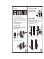
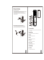
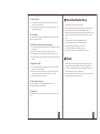
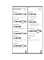
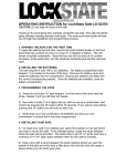
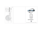
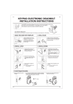
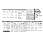
7. Install Inside Mounting Plate 5. Install Strike a b Mounting Pass the IC wire through the wire hole on the Plate mounting plate and fix the mounting plate with screws. If outside lock assembly is lopsided, IC wire please loosen the screws to adjust it's position Screws and tighten the screws again. c a. Half-close the door to lay the latchbolt against the door frame. Mark the position of faceplate as an indication. Place the strike against the door frame and mark it's erimeter. Be sure the center of strike is perfectly aligned with the center of faceplate. b. Drill a ø25.4mm (1") hole with 13mm (1/2") depth on the center of strike outline. Then use the chisel to scrape out the door frame for 1.6mm (1/16") deep within your pencil mark. Ensure to chisel deep enough to allow the strike lay flush with the frame surface. c. Insert the strike and tighten it with screws. Note : please use “tapping screws” for metal door. 8. Install Receiver Module a. Remove the battery cover (push it up and pull it out). b. Connect the IC wire and ensure the turn piece is horizontal, so that the tailpiece is able to engaged with the inside lever/knob. Then attach receiver module to the door with screws. It's optional to use the attached wood screw. (Wood screw only for wood door) a 6. Install Keypad Assembly b wood screw Battery Cover a. Place the leverset/knobset against keypad with tailpiece in vertical position inserted through cam of the latch. screws Tailpiece Receiver Module Turn Piece Outside Lever c. Insert 4 (AA) 1.5V alkaline batteries and put the battery cover back to the receiver module. Tailpiece should be turned to vertical. Outside Knob c b. Pass the IC wire over the latch to the interior side of door. IC wire 3 Inside Lever Inside Knob 4