1
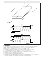
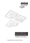
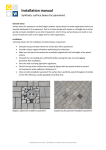
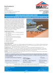
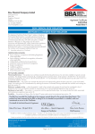
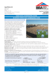
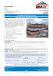
IKO PLC APPROVAL INSPECTION TESTING CERTIFICATION Appley Lane North Appley Bridge Wigan Lancashire WN6 9AB Tel: 0844 4127207 Fax: 0844 4127208 TECHNICAL APPROVALS FOR CONSTRUCTION Agrément Certificate 14/5149 e-mail: [email protected] website: www.ikogroup.co.uk Product Sheet 1 IKO INVERTED ROOF SYSTEM IKO ENERTHERM INVERTED ROOF SYSTEM This Agrément Certificate Product Sheet(1) relates to the IKO enertherm Inverted Roof System, which uses extruded polystyrene boards. The XPS boards are used in conjunction with the IKO enertherm WCL (water control layer) and gravel ballast or paving protection, for inverted flat untrafficked roofs, and balconies and terraced roofs subject to pedestrian access only. When used in conjunction with a suitable root barrier the system may be used in green roof applications. The IKO enertherm Inverted Roof System may be used with zero pitch and slopes between 1:80 and 1:6. (1) Hereinafter referred to as ‘Certificate’. CERTIFICATION INCLUDES: • factors relating to compliance with Building Regulations where applicable • factors relating to additional non-regulatory information where applicable • independently verified technical specification • assessment criteria and technical investigations • design considerations • installation guidance • regular surveillance of production • formal three-yearly review. KEY FACTORS ASSESSED Thermal performance — the system can contribute towards the thermal performance of a roof. The design thermal conductivity (lU), including moisture correction factor, of the boards is 0.034 W·m–1·K–1 for XPS thicknesses greater than or equal to 100 mm and 0.035 W·m–1·K–1 for XPS thicknesses less than 100 mm (see section 6). Condensation risk — the system will contribute to limiting the risk of surface and interstitial condensation (see section 7). Resistance to foot traffic — the system, when installed on appropriate decks finished with a gravel ballast layer, paving slabs or a green roof, can be used on untrafficked roofs with limited pedestrian access associated with maintenance operations, and pedestrian access roofs (on balconies and roof terraces) subject to foot traffic only (see section 8). Durability — the system will remain effective as an insulant for at least 25 years, as long as the IKO enertherm WCL (water control layer) remains unchanged (see section 12). The BBA has awarded this Certificate to the company named above for the system described herein. This system has been assessed by the BBA as being fit for its intended use provided it is installed, used and maintained as set out in this Certificate. On behalf of the British Board of Agrément Date of First issue: 12 September 2014 John Albon — Head of Approvals Claire Curtis-Thomas Energy and Ventilation Chief Executive The BBA is a UKAS accredited certification body — Number 113. The schedule of the current scope of accreditation for product certification is available in pdf format via the UKAS link on the BBA website at www.bbacerts.co.uk Readers are advised to check the validity and latest issue number of this Agrément Certificate by either referring to the BBA website or contacting the BBA direct. British Board of Agrément Bucknalls Lane Watford Herts WD25 9BA ©2014 Page 1 of 13 tel: 01923 665300 fax: 01923 665301 e-mail: [email protected] website: www.bbacerts.co.uk Regulations In the opinion of the BBA, the IKO enertherm Inverted Roof System, if installed, used and maintained in accordance with this Certificate, will meet or contribute to meeting the relevant requirements of the following Building Regulations (the presence of a UK map indicates that the subject is related to the Building Regulations in the region or regions of the UK depicted): The Building Regulations 2010 (England and Wales) (as amended) Requirement: C2(c) Resistance to moisture Comment: Requirement: L1(a)(i) The system can contribute to reducing the risk of condensation. See sections 7.3 and 7.4 of this Certificate. Comment: Regulation: 7 The system can contribute to satisfying this Requirement. See sections 6.1 and 6.3 of this Certificate. Comment: Regulation: 26 Regulation: 26A Regulation: 26A Regulation: 26B The system is acceptable. See section 12.1 and the Installation part of this Certificate. Comment: The system can contribute to satisfying these Regulations. See sections 6.1 and 6.3 of this Certificate. Conservation of fuel and power Materials and workmanship CO2 emission rates for new buildings Fabric energy efficiency rates for new dwellings (applicable to England only) Primary energy consumption rates for new buildings (applicable to Wales only) Fabric performance values for new dwellings (applicable to Wales only) The Building (Scotland) Regulations 2004 (as amended) Regulation: 8(1)(2) Durability, workmanship and fitness of materials Comment: Regulation: 9 Standard: 3.15 The system is acceptable. See sections 11.1 and 12.1 and the Installation part of this Certificate. Comment: The system can contribute to satisfying this Standard, with reference to clauses 3.15.1(1)(2), 3.15.3(1)(2), 3.15.4(1)(2), 3.15.5(1)(2), and 3.15.6(1)(2). See sections 7.3 and 7.5 of this Certificate. Standard: Standard: Carbon dioxide emissions Building insulation envelope 6.1(b) 6.2 Comment: Standard: 7.1(a)(b) Comment: Regulation: 12 Building standards applicable to construction Condensation The system can contribute to satisfying these Standards, with reference to clauses, or parts of, 6.1.1(1), 6.1.2(1)(2), 6.1.4(1)(2), 6.1.5(1), 6.1.6(1)(2), 6.1.7(2), 6.1.8(2) to 6.1.10(2), 6.2.1(1)(2), 6.2.2(1), 6.2.3(1)(2), 6.2.4(1)(2), 6.2.5(2), 6.2.6(1)(2) to 6.2.11(1)(2), 6.2.12(2) and 6.2.13(1)(2). See sections 6.1 and 6.3 of this Certificate. Statement of sustainability The system can contribute to satisfying the relevant requirements of Regulation 9, Standards 1 to 6, and, therefore, will contribute to a construction meeting a bronze level of sustainability as defined in this Standard. In addition, the system can contribute to a construction meeting a higher level of sustainability as defined in this Standard, with reference to clauses 7.1.4(1)(2) [Aspects 1(1)(2) and 2(1)], 7.1.6(1)(2) [Aspects 1(1)(2) and 2(1)] and 7.1.7(1)(2) [Aspect 1(1)(2)]. See section 6.1 of this Certificate. Building standards applicable to conversions Comment: All comments given for the system under Regulation 9, Standards 1 to 6, also apply to this Regulation, with reference to clause 0.12.1(1)(2) and Schedule 6(1)(2). (1) Technical Handbook (Domestic). (2) Technical Handbook (Non-Domestic). The Building Regulations (Northern Ireland) 2012 Regulation: 23 Fitness of materials and workmanship Comment: Regulation: 29 The system is acceptable. See section 12.1 and the Installation part of this Certificate. Comment: Regulation: 39(a)(i) The system can contribute to satisfying this Regulation. See section 7.3 of this Certificate. Comment: Regulation: 40(2) The system can contribute to satisfying this Regulation. See sections 6.1 and 6.3 of this Certificate. Comment: The system can contribute to satisfying this Regulation. See sections 6.1 and 6.3 of this Certificate. Condensation Conservation measures Target carbon dioxide emission rate Construction (Design and Management) Regulations 2007 Construction (Design and Management) Regulations (Northern Ireland) 2007 Information in this Certificate may assist the client, CDM co-ordinator, designer and contractors to address their obligations under these Regulations. See sections: 1 Description (1.2 and 1.3) and 3 Delivery and site handling (3.4) of this Certificate. Page 2 of 13 Additional Information NHBC Standards 2014 NHBC accepts the use of the IKO enertherm Inverted Roof System, provided it is installed, used and maintained in accordance with this Certificate, in relation to NHBC Standards, Chapter 7.1 Flat roofs and balconies. CE marking The manufacturer has taken the responsibility of CE marking the insulation component of the system in accordance with harmonised European Standard BS EN 13164 : 2012. An asterisk (*) appearing in this Certificate indicates that data shown is given in the manufacturer’s Declaration of Performance. Technical Specification 1 Description 1.1 The IKO enertherm Inverted Roof System consists of extruded polystyrene (XPS) boards, rebated for lap jointing (see Figure 1), used with the IKO enertherm WCL (water control layer) for use with a gravel ballast, paving or green roof finish. 1.2 Characteristics of the boards are given in Table 1. Table 1 Nominal characteristics Work size (mm) 1250 x 600 Overall size (mm) 1265 x 615 Standard thicknesses (mm)(1) 70, 130, 160, 180, 200 and 220 Water vapour permeability (MN·s·g ·m ) 625 Minimum compressive strength* at 10% compression (kPa) 300 Edge profile (see Figure 1) rebated –1 –1 (1) T hicknesses > 220 mm and up to a maximum thickness of 360 mm are achieved by combining up to three insulation boards. 1.3 The IKO enertherm WCL is used as a filter layer and water control layer between the insulation and the roof ballast layer. The nominal properties are shown in Table 2. Table 2 Physical properties of the IKO enertherm WCL (water control layer) Length (m) 100 Width (m) 1.5 Weight (g·m–2) 100 Water vapour resistance (MN·s·g–1) 0.1 Lap joints (mm) — unsealed 300 1.4 A suitable root barrier is used in green roof applications. Laps in the root barrier are sealed using a suitable root barrier tape. 1.5 Ancillary items outside the scope of this Certificate include: • gravel ballast washed, rounded and of nominal 16 mm to 32 mm in size, laid to a minimum depth of 50 mm, or • paving of minimum 40 mm thickness. See sections 9.1 and 9.2 • green roof finish, including root barrier, filter fleece and drainage/water retention layer to manufacturer’s specification, which also meet the relevant requirements of ETAG 031 : 2010 (see section 4.2). Page 3 of 13 Figure 1 Rebate detail 2 Manufacture 2.1 Raw materials are heated to form a molten plastic mix, which is injected with blowing agent. The foam is extruded and shaped in a die. An automated process cures and cuts the product to the required size. 2.2 As part of the assessment and ongoing surveillance of product quality, the BBA: • agreed with the manufacturer the quality control procedures and product testing to be undertaken • assessed and agreed the quality control operated over batches of incoming materials • monitored the production process and verified that it is in accordance with the documented process • evaluated the process for management of nonconformities • checked that equipment has been properly tested and calibrated • undertaken to carry out the above measures on a regular basis through a surveillance process, to verify that the specifications and quality control operated by the manufacturer are being maintained. Page 4 of 13 2.3 The manufacturer’s management system has been assessed and registered as meeting the requirements of BS EN ISO 9001 : 2008, BS EN 14001 : 2004, BS EN ISO 50001 : 2011 and OHSAS 18001 : 2007 by Bureau Veritas Certification (Certificate BE001519-1, BE005999-2, BEL 130711 and BE006000-1). 3 Delivery and site handling 3.1 Boards are wrapped in polythene and delivered to site on pallets or bearers. Each pack shows the manufacturer’s name, grade, type marking, and the BBA identification mark incorporating the number of this Certificate. 3.2 Boards must be protected from prolonged exposure to sunlight and should be stored under cover or protected with light-coloured opaque sheets. 3.3 Care must be taken to avoid contact with solvents and materials containing organic components. 3.4 Boards must be stored flat, on a clean, level surface and under cover to protect them from high winds. They must not be exposed to open flame or other ignition sources. 3.5 Damaged boards must not be used. Assessment and Technical Investigations The following is a summary of the assessment and technical investigations carried out on the IKO enertherm Inverted Roof System. Design Considerations 4 Use 4.1 The IKO enertherm Inverted Roof System is suitable for use on inverted flat or zero pitch untrafficked roofs, and balconies and terraced roofs subject to pedestrian access only, with a gravel ballast, paved or green roof finish and a suitably designed timber, concrete or metal structural deck and appropriate fully supported waterproofing system. 4.2 For the purpose of this Certificate: • flat roofs are defined as those roofs having either a minimum finished fall between 1:80 and 1:6, or zero pitch with finished falls from 0 to 1:80. For design purposes on sloping flat roofs, twice the minimum finished fall should be assumed, unless a detailed analysis of the roof is available, including overall and local deflection, direction of falls etc. See also BBA Information Bulletin No 4. Untrafficked roof • a roof consisting of the structural deck and all the layers on it, including waterproofing, insulation and a surface protective layer not designed for foot traffic above that required for maintenance of roof and/or technical equipment. Pedestrian access roof • a roof consisting of the structural deck and all the layers on it, including waterproofing, thermal insulation and a surface protective layer designed for foot traffic and gathering of people greater than that required for maintenance. Green roof • a roof consisting of the structural deck and all the layers on it, including waterproofing, thermal insulation and a thin layer of growing medium planted with vegetation and possibly including areas of paving. 4.3 A roof ballast layer must be installed as work progresses, to protect the insulation boards and the IKO enertherm WCL from the effects of wind uplift and UV degradation. The ballasted roof finish may be either gravel ballast, paving or a green roof system, which must be assessed by a specialist for its suitability according to region exposure and building height. In addition, the dead load imposed by the finish (including the saturated weight of a green roof) must be allowed for in calculating the total acceptable load on the deck. Care must be taken to ensure that upgraded roofs are capable of carrying the increased load and depth of the installed system. Ballast must not be stacked in one place on the roof unless the roof is capable of supporting it. 4.4 Gravel ballast should be washed, rounded and of nominal 16 mm to 32 mm in size, laid to a minimum thickness of 50 mm. The minimum size of ballast depends on the wind loads and parapet height to prevent wind scour of the ballast. The ballast should be installed in accordance with BS EN 1991-1-4 : 2005 and its National Annex. 4.5 The gravel ballast specification given in section 4.4 is suitable in sheltered regions, or buildings up to 10 storeys. On buildings up to 15 storeys, this specification may be used, but the perimeter must be loaded with paving determined by reference to BS EN 1991-1-2 : 2002. For other exposure conditions or tall buildings, specialist advice should be sought. 4.6 A paving finish ballast comprising a minimum 40 mm of standard pressed concrete paving slabs is suitable in sheltered regions and in buildings up to 15 storeys. For other exposure conditions or tall buildings, specialist advice should be sought. 4.7 The Green Roof Guide states that for inverted roofs, a green roof can be used as ballast, provided the weight of the green roof is the same as a required gravel ballast finish. The growing medium must have resistance to wind and water erosion and be spread over a suitable filter and drainage layer. The green roof covering should be assessed for wind uplift with sufficient growing medium weight calculated for roof ballast. The green roof specification, including Page 5 of 13 growing medium, geotextile filter fleece, drainage/water-retention layer and root barrier is to be determined by the specialist supplier. 4.8 The IKO enertherm XPS should be overlaid with the IKO enertherm WCL, which acts as a filter layer preventing fines and other debris from passing through, and also as a water flow reducing layer minimising cold rainwater flowing between the insulation and the roof waterproofing with consequent heat loss. This membrane may be covered with either a gravel ballast or paving finish (see Figure 2). In green roof applications, the IKO enertherm XPS must be overlaid first with the IKO enertherm WCL, and additionally a root barrier installed on top to prevent root penetration, before finishing with the green roof specification. 4.9 The IKO enertherm WCL is to be laid with 300 mm laps, overlapping in the downward direction of the flat roof slope. At upstands and penetrations the membrane must be turned up to finish above the surface of the ballast layer and turned down at drainage outlets. Figure 2 Typical installation detail — gravel/paving ballast finish Figure 3 Typical installation detail — green roof finish 4.10 Concrete, metal or timber roofs should be designed in accordance with the relevant provisions of BS 6229 : 2003, BS 8217 : 2005 and BS 8218 : 1998, in particular to accommodate the weight of the ballast layer. 4.11 Decks should be covered with one or more of the following roof waterproofing specifications: • IKO Reinforced bitumen membrane in accordance with the recommendations of Table 5 of BS 8747 : 2007, and installed to the relevant clauses of BS 8217 : 2005 • IKO Permaphalt mastic asphalt laid in accordance with BS 8218 : 1998 • IKO PermaTEC Hot Melt Systems which are the subject of a current Agrément Certificate, laid in accordance with, and within the limitations imposed by, that Certificate • IKO liquid applied Polimar Systems which are the subject of a current Agrément Certificate, laid in accordance with, and within the limitations imposed by, that Certificate. 4.12 The roof shall be designed with adequate falls(1). (1) U nless the roof waterproofing system has been specifically designed and approved for use in a zero pitch roof application. For zero pitch roofs it is particularly important to identify the correct drainage points, to ensure that the drainage provided is sufficient and effective. Page 6 of 13 4.13 It is essential that roof falls and drainage paths are correctly designed to avoid ponding and subsequent risk of silt build up, stresses in freezing conditions and to reduce water entry in the event of a failure in the waterproofing layer. 4.14 Dual level roof drainage should be provided in accordance with BS 6229 : 2003 and BS EN 12056-3 : 2000 to drain water off at the level of the IKO enertherm WCL and also at the level of the roof waterproofing. See Figures 6 to 8. 4.15 Drainage points need to be located at the lowest point of the roof, to facilitate the effective removal of rainwater. Care is needed to identify these locations. For example, precast concrete decks will deflect between spans, and mid-span may be the lowest point of the roof rather than roof edges or column supports. 4.16 Where there is a risk from plasticiser migration or other contaminants from the roof waterproofing (such as PVC single ply membranes) a suitable plastic fibre or similar isolating sheet must be interposed between the roof waterproofing and the XPS insulation boards. For loose laid single layer roof waterproofing membranes, a cushion layer should be interposed. 5 Practicability of installation The system is designed to be installed by a competent general builder or contractor experienced with this type of system. 6 Thermal performance 6.1 Calculations of the thermal transmittance (U value) of a specific roof construction should be carried out in accordance with BS EN ISO 6946 : 2007 and BRE Report BR 443 : 2006, using the design thermal conductivity (U) (which is the declared D* with addition of moisture correction) and fx drainage factor for the system as given below. See also BBA Information Bulletin No 4, BS EN ISO 10456 : 2007 and ETAG 031 : 2010. • 0.035 W·m–1·K–1 — design thermal conductivity (U) (including moisture correction factor) for XPS thicknesses less than 100 mm • 0.034 W·m–1·K–1 — design thermal conductivity (U) (including moisture correction factor) for XPS thicknesses greater than or equal to 100 mm • fx = 0.001 — drainage factor for systems incorporating the IKO enertherm WCL. The value of a completed roof will depend on the insulation thickness, and type of substrate and internal finish. When considering insulation requirements, designers should refer to the detailed guidance contained in the documents supporting the national Building Regulations. The U values shown in Table 3 indicate that the system can contribute to a roof achieving typical U values referred to in those supporting documents. Table 3 Example U values (1) for flat roof and zero pitch applications (incorporating the IKO enertherm WCL) Required U Value (W·m–2·K–1) IKO enertherm XPS standard stock thickness required(2) (mm) p(3) ≤ 3 p(3) = 8 0.10 160 +160 180 + 180 0.13 180 + 70 130 + 130 0.15 220 160 + 70 0.16 200 220 0.18 180 200 0.20 160 180 0.25 130 130 (1) 200 mm dense concrete deck (2.5 W·m ·K ). (2) Thickest board as bottom layer, when double/triple layer used. (3) Values for p taken as examples of best to worst case for all UK locations. –1 –1 6.2 Rainfall reaching the roof waterproofing membrane will temporarily affect the rate of heat loss from the roof and should be accounted for by adding a correction (∆Ur) to the calculated roof U value in accordance with Annex D.4 of BS EN ISO 6946 : 2007, as follows: ∆Ur = pfx (R1/RT)2 where: ∆Ur = correction to the calculated thermal transmittance of the roof element (W·m–2·K–1). p(1) = average rate of precipitation during the heating season (mm·day–1). f = drainage factor giving the fraction of p reaching the waterproof membrane. x = factor for increased heat loss caused by rainwater flowing on the membrane (W·day·m–2·K–1·mm–1). R1 = thermal resistance of the layer of the insulation above the waterproofing membrane (m2·K·W–1). RT = total thermal resistance of the construction before application of the correction (m2·K·W–1). fx = 0.001 for the system incorporating the IKO enertherm WCL (water control layer). (1) V alues for average monthly rainfall for different UK locations can be found at www.metoffice.gov.uk/climate/uk/averages/19812010/. The values for October to March should be summed and divided by 182 to obtain an average ‘p’ in mm·day–1 for the heating season. Page 7 of 13 6.3 The system can contribute to maintaining continuity of thermal insulation at junctions. For Accredited Construction Details, the corresponding -values (Psi) in BRE Information Paper IP 1/06, Table 3, may be used in carbon emission calculations in Scotland and Northern Ireland. Detailed guidance for other junctions and on limiting heat loss by air infiltration can be found in: England and Wales — Approved Documents to Part L and for new thermal elements to existing buildings, Accredited Construction Details (version 1.0). See also SAP 2009 Appendix K and the iSBEM User Manual for new-build Scotland — Accredited Construction Details (Scotland) Northern Ireland — Accredited Construction Details (version 1.0). 7 Condensation risk 7.1 Warm water trapped under the boards is likely to be replaced by colder water during rainfall. Therefore, during heavy or continuous rainfall the roof waterproofing and the deck will be cooled. If condensation does occur it will be short-term, disappearing when the rain stops. 7.2 Risk of interstitial condensation will be minimal with concrete decks but metal and timber decks will be subjected to short periods of moisture; therefore timber must be treated with a suitable preservative in accordance with BS 8417 : 2011. Interstitial condensation 7.3 Roofs will adequately limit the risk of interstitial condensation when they are designed and constructed in accordance with BS 5250 : 2011, Section 4 and Annex D and H. Surface condensation 7.4 Roofs will adequately limit the risk of surface condensation when the thermal transmittance (U value) does not exceed 0.35 W·m–2·K–1 at any point and the junctions with walls are designed in accordance with the relevant requirements of Limiting thermal bridging and air leakage : Robust construction details for dwellings and similar buildings, TSO 2002, or BRE Information Paper IP 1/06. 7.5 In Scotland, constructions will be acceptable when the thermal transmittance (U value) does not exceed 1.2 W·m–2·K–1 at any point. Guidance may be obtained from BS 5250 : 2011, Section 4, and BRE Report BR 262 : 2002. 8 Resistance to foot traffic The XPS has adequate resistance to the loads associated with light maintenance traffic on roofs, and to pedestrian foot traffic on balconies and roof terraces. 9 Behaviour in relation to fire 9.1 The IKO enertherm Inverted Roof System is ballasted with either aggregate (minimum depth of 50 mm), sand/ cement screed to a thickness of at least 30 mm, or fully supported cast stone or mineral slabs of at least 40 mm thickness. Therefore the roof may be considered to be of designation AA (low vulnerability in Scotland) and meets or satisfies the requirements of the national Building Regulations, thus: England and Wales — Requirement B4(2) Scotland — Mandatory Standard 2.8, clause 2.8.1(1)(2) (1) Technical Handbook (Domestic). (2) Technical Handbook (Non-Domestic). Northern Ireland — Regulation 36(b). 9.2 The designation of other roof covering specifications should be confirmed as required by the national Building Regulations. 9.3 The IKO enertherm Inverted Roof System should not be laid over compartment walls. 10 Effect on roof coverings The protected inverted roof system will provide solar protection and also limit the range of temperatures to which the waterproofing membrane will be subjected. Placing the insulation on top of the roof covering will normally lead to an extended life of the waterproof membrane. 11 Maintenance 11.1 The inverted roof concept should require little or no maintenance, other than annual removal of any plants (in the case of gravel/paving finish), cleaning/checking of water outlets and gutters if necessary and checking that the gravel ballast is still in place and not interfering with or blocking gullies or outlets. Any displaced ballast, for example by wind scouring, should be promptly returned to its original state. 11.2 The use of chemicals (eg weed killers) should be checked for compatibility with the insulation, IKO enertherm WCL and the deck waterproofing layer. The Certificate holder can advise on the suitability of a particular system. Page 8 of 13 11.3 Leaks in the waterproof membrane can be accessed by removal of the gravel ballast, paving or green roof covering, root barrier (green roofs only), IKO enertherm WCL and insulation boards, taking care not to damage the water-reducing layer. 11.4 Protected inverted roofs can be upgraded by the addition of insulation so long as there is sufficient height in the parapets and roof lights. This may also require additional ballast, therefore the structural deck must be adequate to support the extra loading from the increase in weight. 11.5 The Certificate holder must approve any upgrading using a loose layer of insulation on top of the existing insulation. 12 Durability 12.1 The XPS board is rot resistant and, as long as the IKO enertherm WCL (water control layer) remains undamaged, will have a life of at least 25 years under normal circumstances. 12.2 Care must be taken to ensure that the gravel ballast, or paving/green roof covering once installed, provides cover to the IKO enertherm WCL at all times to avoid UV degradation of the membrane. Installation 13 General 13.1 The IKO enertherm Inverted Roof System is laid over a compatible and complete waterproofing system (see section 4.11), generally starting at the point of access in a brick bond pattern. 13.2 The XPS boards must be laid flat and tightly interlocked to prevent gaps in the insulation layer. Insulation boards are laid in an advancing front, with the IKO enertherm WCL (water control layer) on top, and the ballast, paving or green roof covering laid as soon as possible to protect the system. 13.3 Where necessary, boards are cut accurately with a fine tooth saw or with a hot wire cutter around any penetrations. 13.4 The IKO enertherm WCL is laid with 300 mm unsealed laps overlapping in the downward direction of the flat roof slope, immediately on top of the insulation boards. At upstands and penetrations the IKO enertherm WCL must be turned up to finish above the surface of the ballast layer and turned down at drainage outlets. See Figures 4 to 8. Figure 4 Parapet upstand detail — gravel/paving finish Page 9 of 13 Figure 5 Parapet upstand detail — green roof finish Figure 6 Water outlet detail — gravel finish Page 10 of 13 Figure 7 Water outlet detail — paving finish IKO enertherm WCL paving slabs on spacer pads drainage outlet IKO enertherm XPS concrete roof deck IKO waterproofing membrane Figure 8 Water outlet detail — green roof finish 14 Protective finishes Gravel ballast finish 14.1 In order to prevent flotation, wind uplift and UV degradation, the system must be covered with gravel ballast as the work proceeds, to a minimum thickness of 50 mm. 14.2 It is essential that the ballast is carefully placed directly over the IKO enertherm WCL laid with 300 mm unsealed lap joints, and that complete depth and cover is achieved over the entire surface of the system. 14.3 Gravel must not contain excessive fines in order to prevent clogging of gullies and outlets and to discourage organic growth. Paving slabs 14.4 Cast stone or mineral slab pavings of at least 40 mm thickness on boards 50 mm thick, and 50 mm on thicker boards, must meet the requirements of sections 7.3 and 9 of this Certificate. Paving slabs can either be laid fully supported, or may be supported using proprietary spacer pads in accordance with the manufacturer’s instructions. 14.5 The paving slab finish is laid directly over the IKO enertherm WCL laid with 300 mm unsealed lap joints. Roof garden 14.6 A suitable root barrier or a water retention/drainage layer with an integral root barrier is laid on top of the IKO enertherm WCL. A suitable root barrier tape is used to seal laps in the root barrier, in accordance with the manufacturer’s instructions. Page 11 of 13 14.7 The green roof system including growing medium, geotextile filter fleece, water retention/drainage layer and a root barrier, installed in accordance with the manufacturer’s instructions. 14.8 All upstands, roof perimeters, drainage outlets and other protrusions through the green roof, should be protected by a minimum 500 mm wide un-vegetated barrier such as 16 mm to 32 mm rounded gravel aggregate or concrete paving slabs. Technical Investigations 15 Tests Tests were carried out by the BBA on the XPS board and the results assessed to determine: • compressive strength • compressive creep • deformation under specified compressive load and temperature • dimensional stability • water vapour transmission • water flow through an inverted roof • long-term water absorption by diffusion • resistance to freeze-thaw • thermal conductivity • bowing under a thermal gradient. 16 Investigations 16.1 The following independent data relating to the IKO enertherm WCL were examined: • tensile strength • resistance to static loading (point loading) • resistance to water penetration • hydrostatic head • water vapour transmission. 16.2 The manufacturing process and quality control procedures were evaluated and details obtained of the quality and composition of materials used. Bibliography BS 5250 : 2011 Code of practice for control of condensation in buildings BS 6229 : 2003 Flat roofs with continuously supported coverings — Code of practice BS 8217 : 2005 Reinforced bitumen membranes for roofing Code of practice BS 8218 : 1998 Code of practice for mastic asphalt roofing BS 8417 : 2011 Preservation of wood — Code of practice BS 8747 : 2007 Reinforced bitumen membranes (RBMs) for roofing — Guide to selection and specification BS EN 1991-1-2 : 2002 Eurocode 2 : Design of concrete structures — General rules — Structural fire design BS EN 1991-1-4 : 2005 Eurocode 1 — Actions on structures — General actions — Wind actions NA to BS EN 1991-1-4 : 2005 UK National Annex to Eurocode 1 : Actions on structures — General actions — Wind actions BS EN 12056-3 : 2000 Gravity drainage systems inside buildings — Roof drainage, layout and calculation BS EN 13164 : 2012 Thermal insulation products for buildings — Factory made extruded polystyrene foam (XPS) products — Specification BS EN ISO 6946 : 2007 Building components and building elements — Thermal resistance and thermal transmittance — Calculation method BS EN ISO 9001 : 2008 Quality management systems — Requirements BS EN ISO 10456 : 2007 Building materials and products — Hygrothermal properties — Tabulated design values and procedures for determining declared and design thermal values BS EN ISO 14001 : 2004 Environmental Management systems — Requirements with guidance for use BS EN ISO 50001 : 2011 Energy management systems — Requirements with guidance for use BRE Information Paper IP 1/06 Assessing the effects of thermal bridging at junctions and around openings Page 12 of 13 BRE Report (BR 262 : 2002) Thermal insulation: avoiding risks BRE Report (BR 443 : 2006) Conventions for U-value calculations ETAG 031 : 2010 Guideline for European Technical Approval of Inverted Roof Insulation Kits OHSAS 18001 : 2007 Occupational health and safety management systems — requirements Conditions of Certification 17 Conditions 17.1 This Certificate: • relates only to the product/system that is named and described on the front page • is issued only to the company, firm, organisation or person named on the front page — no other company, firm, organisation or person may hold or claim that this Certificate has been issued to them • is valid only within the UK • has to be read, considered and used as a whole document — it may be misleading and will be incomplete to be selective • is copyright of the BBA • is subject to English Law. 17.2 Publications, documents, specifications, legislation, regulations, standards and the like referenced in this Certificate are those that were current and/or deemed relevant by the BBA at the date of issue or reissue of this Certificate. 17.3 This Certificate will remain valid for an unlimited period provided that the product/system and its manufacture and/or fabrication, including all related and relevant parts and processes thereof: • are maintained at or above the levels which have been assessed and found to be satisfactory by the BBA • continue to be checked as and when deemed appropriate by the BBA under arrangements that it will determine • are reviewed by the BBA as and when it considers appropriate. 17.4 The BBA has used due skill, care and diligence in preparing this Certificate, but no warranty is provided. 17.5 In issuing this Certificate, the BBA is not responsible and is excluded from any liability to any company, firm, organisation or person, for any matters arising directly or indirectly from: • the presence or absence of any patent, intellectual property or similar rights subsisting in the product/system or any other product/system • the right of the Certificate holder to manufacture, supply, install, maintain or market the product/system • actual installations of the product/system, including their nature, design, methods, performance, workmanship and maintenance • any works and constructions in which the product/system is installed, including their nature, design, methods, performance, workmanship and maintenance • any loss or damage, including personal injury, howsoever caused by the product/system, including its manufacture, supply, installation, use, maintenance and removal • any claims by the manufacturer relating to CE marking. 17.6 Any information relating to the manufacture, supply, installation, use, maintenance and removal of this product/ system which is contained or referred to in this Certificate is the minimum required to be met when the product/system is manufactured, supplied, installed, used, maintained and removed. It does not purport in any way to restate the requirements of the Health and Safety at Work etc. Act 1974, or of any other statutory, common law or other duty which may exist at the date of issue or reissue of this Certificate; nor is conformity with such information to be taken as satisfying the requirements of the 1974 Act or of any statutory, common law or other duty of care. British Board of Agrément Bucknalls Lane Watford Herts WD25 9BA ©2014 Page 13 of 13 tel: 01923 665300 fax: 01923 665301 e-mail: [email protected] website: www.bbacerts.co.uk