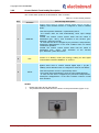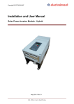
1
Copyright ELECTROINVENT Installation and User Manual for Solar Power Control System / Hybrid May, 2015 IUM - SPCS_H - Rev.00_May 2015.docx Copyright ELECTROINVENT Contents 1 2 3 4 5 Introduction ....................................................................................................................................... 3 1.1 Instructions for safety operation............................................................................................... 4 1.2 Warranty ................................................................................................................................. 4 1.3 Scope of delivery..................................................................................................................... 4 1.4 Technical parameters .............................................................................................................. 5 1.5 Label with technical parameters .............................................................................................. 6 Warnings for danger and attention................................................................................................... 7 Installation of Solar Power Control System / HYBIRD..................................................................... 8 3.1 Mechanical installation ............................................................................................................ 8 3.2 Opening of the SPCS / H unit .................................................................................................. 9 3.2.1 Door opening ........................................................................................................ 9 3.3 Block diagram and working principle of the SPCS / H unit ..................................................... 10 3.4 Choice of PV fuses................................................................................................................ 11 3.5 Choice of place for installation ............................................................................................... 11 3.6 Electrical Installation ............................................................................................................. 12 3.6.1 Cable inputs/outputs ........................................................................................... 12 3.6.2 Overview of SPCS / H Main Components Location............................................. 13 3.6.3 Electrical Connection of SPCS / H unit ............................................................... 14 3.6.4 Power Connections of PV Strings, AC Grid and Pump AC Induction Motor......... 14 3.6.5 Connection of the Communication Interface ....................................................... 17 3.6.6 Inverter Module Input – Output Interface Description .......................................... 18 3.6.7 Connection of SPCS / H Communication Modules.............................................. 20 3.6.8 Water Level Control - Option 5 ........................................................................... 21 3.6.9 Control Switch Functionality Description ............................................................. 22 Replacement of Defected Components.......................................................................................... 23 4.1 Replacement of fuse ............................................................................................................. 23 4.2 Replacement of discharger for overvoltage transients protection (arresters) .......................... 24 4.3 Replacement of fan and finger guard filters ........................................................................... 24 4.4 Replacement of a cooling fan ................................................................................................ 25 Software Functional Description .................................................................................................... 26 5.1 Parameters of frequency inverter (Software Rev.36) ............................................................. 26 5.1.1 Menu 0 ( a ) – Setting of inverter output frequency ............................................. 26 5.1.2 Menu 1 ( b ) - Visualization ................................................................................. 26 5.1.3 Menu 2 ( c ) – Motor Parameters ........................................................................ 26 5.1.4 Menu 3 ( d ) – Common adjustments .................................................................. 27 5.1.5 Menu 4 ( e ) - Multifunctional inputs ................................................................... 27 5.1.6 Menu 5 ( f ) – Multifunctional outputs .................................................................. 27 5.1.7 Menu 6 ( g ) – Configuring of analog input .......................................................... 28 5.1.8 Menu 7 ( h ) – Ramp acceleration and deceleration ............................................ 28 5.1.9 Menu 8 ( I ) – Current limitation .......................................................................... 28 5.1.10 Menu 9 ( j) – Communication .......................................................................... 28 5.1.11 Menu 10 ( l ) – V-Hz curve .................................................................................. 28 5.1.12 Menu 11 ( n ) – Solar Control.............................................................................. 29 5.1.13 Menu 12 ( o ) – Visualization of the main operating variables ............................. 29 5.1.14 Menu 13 ( p ) – Pump operation control .............................................................. 29 5.2 Configuration and Activation of Digital Input / Output Functions............................................. 30 5.2.1 Configuration and activation of digital input functions .......................................... 30 5.2.2 Configuration and activation of digital output functions ....................................... 31 5.3 Description of Inverter Module Menus and Parameters ......................................................... 33 5.3.1 Menu 0 ( a ) – “Setting of inverter output frequency” ........................................... 33 5.3.2 Menu 1 ( b ) – “Visualization” .............................................................................. 33 5.3.3 Menu 2 ( c ) – “Motor Parameters” ...................................................................... 34 5.3.4 Menu 3 ( d ) – “Common adjustments”................................................................ 34 5.3.5 Menu 4 ( e ) – “Multifunctional inputs” ................................................................. 35 5.3.6 Menu 5 ( f ) – “Multifunctional outputs” ................................................................ 36 5.3.7 Menu 6 ( g ) – “Configuring of analog input” ........................................................ 36 5.3.8 Menu 7 ( h ) – “Acceleration and deceleration ramp” .......................................... 36 5.3.9 Menu 8 ( I ) – “Current limitation” ........................................................................ 36 5.3.10 Menu 9 ( j ) – “Communication” .......................................................................... 37 5.3.11 Menu 10 ( l ) – “V-Hz curve”................................................................................ 37 5.3.12 Menu 11 ( n ) – “Solar Control” ........................................................................... 37 5.3.13 Menu 12 ( o ) – “Visualization of the main operating variables” ........................... 38 5.3.14 Menu 13 ( p ) – “Control of pump operation” ....................................................... 38 5.4 MODBUS Communication ..................................................................................................... 40 5.4.1 Supported functions of MODBUS protocol .......................................................... 40 5.4.2 Addressing of parameters and variables of the drive by MODBUS protocol ........ 40 5.4.3 Principle of addressing ....................................................................................... 40 5.4.4 Format of parameters and variables of the drive accessible through MODBUS ........................................................................................................... 40 5.5 Electronic Protections and LED-indications of the Inverter Operating State ........................... 43 Contacts ............................................................................................................................................ 46 IUM - SPCS_H - Rev.00_May 2015.docx Copyright ELECTROINVENT 1 Introduction Solar Power Control System / Hybrid (SPCS / H) cabinets are designed to supply three phase induction motors in solar pumping systems. These cabinets have a hybrid power input. They could be supplied simultaneously from a 3-phase AC power grid and from a PV array (Figure 1.1). Example diagram of solar pumps installation: Figure 1.1. Typical Solar Pump Installation The SPCS / H cabinet works in a proportional mode, when it is supplied from both, an AC grid and PV panels, the device consumes the maximum possible energy from the PV array and, if the solar energy is not enough to feed the pump (with its rated power), then it consumes the rest necessary energy from the AC power grid. The SPCS / H cabinet could be supplied also only from one power source. For example, only from a PV array. The AC power grid could be switched on from the AC power switch (on the front panel of the cabinet), only when the customer needs it. The SPCS / H cabinet includes Inverter module, HPSI module, AC grid and PV side arresters, PV fuse holders, AC and DC Switches, Control Switch. Optional there could be included communication modules and water level control module. IUM - SPCS_H - Rev.00_May 2015.docx 3/46 Copyright ELECTROINVENT 1.1 Instructions for safety operation The present manual contains important instructions for safety operation, start running into exploitation and operation cabinets type SPCS / H! This manual has to be kept together or near the equipment any time! Photovoltaic installations operate with dangerous for life voltages. All activities regarding assembling and maintenance have to be performed by authorized personnel, familiar with installation, start running into exploitation and operation of photovoltaic equipment and installations. The unit must be used exclusively for purposes, for which it is intended. For good and safety operation of the product, it is important the transport and store keeping to be good, as well as all prescriptions for assembling and installation, service and maintenance to be kept. Respective regional and specific for the country regulations to be kept, as well as the requirements, described in the present document, including instructions for location and assembling (for example the cross section of connecting cables, performing the tightening torque on mechanical and electrical connections, etc.). Used symbols and warning signs: DANGER DANGER means risky situation which, if it is not avoided, can bring to death or to serious injury. ATTENTION ATTENTION refers to cases, which are not connected with human injury. Not conforming to this warning sign can bring to material damages. 1.2 Warranty The data and instructions for assembling and maintenance, given in this manual, are revised regularly and all corrections are included in next issues. In case of breaking the assembling instructions, the warranty claims will not be accepted. We cannot bear any responsibility also in cases of incidents and material damages, caused from wrong use, as well as from actions of not authorized personnel with resulting from these consequences. 1.3 Scope of delivery Table 1.1 Scope of delivery IUM - SPCS_H - Rev.00_May Q- ty Item 1 pc SOLAR POWER CONTROL SYSTEM / HYBRID – SPCS / H unit 1 pc Plastic universal key 1 set Wall mounting kit (Set of mounting plates with bolts) 1 pc Installation and User Manual 4 pcs Spare fuses (15A) for the strings 2015.docx 4/46 Copyright ELECTROINVENT 1.4 Technical parameters The basic technical parameters of Solar Power Control System / Hybrid with power 7.5kW, 11.0kW, 15.0kW and 19.0kW are listed in Table 1.2. Table 1.2 Technical parameters Type SPCS / H Drive power – matched three-phase pumps Main Application Output Power (Motor Pump Power) kW 7.5 Output Voltage (Motor Supply Voltage) VAC 3x400 Input PV Voltage Range VDC 560 – 800 Max. VOC VDC 800 Max. Input DC current per DC input ADC 15 Available Number of PV string inputs Q-ty Recommended PV Panels Power Wp Recommended Total PV Panels Power Wp 14400 Recommended number of strings Q-ty 3 Recommended PV panels per string Q-ty 3 11.0 15.0 4 19.0 5 6 19200 24000 28800 4 5 6 235 – 250 18 - 20 Protection Class IP 54 AC and DC switches Build in PV inputs individual protection By fuses Input AC Grid Voltage VAC Input AC Grid Current AAC 380 - 420 3~ 50/60Hz 16 Operation modes 28 35 40 Manual / Fully automatic Technology Advanced MPPT; IGBT Power Modules Electronic Protections DC Input reversal; Over Load Protection; Output Short circuit; Earth fault protection; Over Voltage; Under Voltage; Over Heating; Dry Run System Lightning protection by surge arresters Digital 4 Digital Inputs; 1 Digital Counting Input Analogue 1 Analogue Input 4- 20mA Relays 2 NO/NC Digital 2 Open Collector Outputs System Inputs and Outputs - Option 1 Inverter Communication Interface Communication with SPCS / H Water Level Control Weight IUM - SPCS_H - Rev.00_May Modbus RS232 / RS485 Option 2 RS232/485 to Ethernet Option 3 RS232 to 3G (GSM communication) Option 4 RS232 to GPRS (GSM communication) Option 5 WLC module allows connection of 1 or 2 sets of liquid level sensors kg 2015.docx 42 42 44 44 5/46 Copyright ELECTROINVENT 1.5 Label with technical parameters The label with the main technical parameters of the unit is located on the upper left inside part of the door. 1 2 Figure 1.2. Label with technical parameters Where: 1. Designation of the product 2. Serial number of the product Description of type designation: SPCS / H - B 1 4 - x x x - х Solar Power Control System / Hybrid Box size Input Voltage Range Motor Supply Voltage 4 = 3x400VAC Corresponding Motor Power (kW) 075 = 7.5 kW; 110 = 11.0 kW; 150 =15.0 kW; 190 = 19.0 kW Options: I - Input / Output Interface E - Communication module - RS232/485 to Ethernet G1 - Communication module - RS232 to 3G (GSM communication) G2 - Communication module - RS232 to GPRS (GSM communication) W – Water Level Control Module Note: Options G1 and G2 could not be built in the cabinet together. Figure 1.3. Description of product designation - see Figure 1.2 pos.1 IUM - SPCS_H - Rev.00_May 2015.docx 6/46 Copyright ELECTROINVENT 2 Warnings for danger and attention DANGER Regional standards for installation must be observed. DANGER Installation, exploitation and maintenance of the unit must be performed by qualified personnel only. DANGER The unit operates with dangerous for life voltages. The strings of photovoltaic modules can be under voltage, when DC switch is turned OFF and the fuses of strings are taken out. DC-link of the unit stays for some time under voltage, even when the AC and DC switches of the unit are turned OFF. After turning OFF the AC and DC Switches, wait 10 minutes, before opening the cabinet door or turning it ON again! DANGER The unit is a part from complete photovoltaic installation. During operation must be observed all instructions for safety, concerning inverter unit and inverter parts, as well as the instructions described in present manual for assembling and exploitation! Have in mind, that after photovoltaic breakdown, automatic restart can follow. DANGER If some information is not clear, please, contact with the service center of “ELECTROINVENT” LTD! ATTENTION Loss of warranty! The unit must not be damaged, as well as it is forbidden to make holes on it. Any transport damage has to be established and reported to supplier before unit installation. IUM - SPCS_H - Rev.00_May 2015.docx 7/46 Copyright ELECTROINVENT 3 Installation of Solar Power Control System / HYBIRD The SPCS / H unit installation must be done in accordance with indicated below steps. 3.1 Mechanical installation The SPCS / H unit has to be mounted on the wall or on the frame, as the cable terminals must be down. Inside the panel, even during installation, never must enter any water or other liquid. The fixing of the panel is done by mounting plates, which must be assembled on the back side of the box (see Figure 3.1.). The mounting plates and fixing elements are shown on Figure 3.1. Figure 3.1. Assembling of mounting plates Figure 3.2. Overall and mounting dimensions IUM - SPCS_H - Rev.00_May 2015.docx 8/46 Copyright ELECTROINVENT Note: Condensate discharge unit (see Figure 3.3) must not be covered. The condensate discharge unit ensures the air circulation in the panel. Condensate discharge Figure 3.3. Bottom view (outside view) 3.2 Opening of the SPCS / H unit 3.2.1 Door opening The cabinet door can be opened and closed with a universal key, which is a part from the delivered set and only when the main AC and DC switches are both turned OFF. 6 1 7 2 3 4 5 Figure 3.4. The door of SPCS / H unit Where: 1. 2. 3. 4. 5. 6. 7. IUM - SPCS_H - Rev.00_May 2015.docx Inverter state LED indication window Lock for opening / closing the cabinet door AC switch Control switch DC switch Label Electrical wiring diagram 9/46 Copyright ELECTROINVENT 3.3 Block diagram and working principle of the SPCS / H unit The block scheme of the unit is shown on Figure 3.5 Figure 3.5. Block scheme of SPCS / H The DC voltage, generated from solar radiation in PV panels, is supplied in the cabinet through PV input terminals (PV+ and PV-). The PV Input Terminals are protected individually with appropriate fuses, corresponding to the string current. Currents from all strings are collected and through DC breaker (Main DC Switch) are supplied to the HPSI module “PV Input”. The AC grid voltage is supplied to the cabinet through the AC Grid Input Terminals. Then through the main AC Switch it is supplied to the HPSI module “AC Input”. The output of the HPSI module forms the inverter’s DC-bus voltage on the DC-link capacitor group. There are power connections between the HPSI module output, the DClink capacitors and the inverter’s power input. There are surge arresters on the PV input side and on the AC grid input side for protection from overvoltage transients, which could be caused either from external (for example lightning), or internal (power stages switching) events. The inverter converts the DC bus voltage into three-phase alternative voltage suitable to control the AC motor, driving the pump. The inverter controls the input parameters of the system and by enough solar radiation supplies the pump motor with voltage 3х400VAC; 50Hz. By insufficient solar radiation there are two possible ways of pump control. First, if the AC grid and PV array are both connected, then we have so called proportional mode - the inverter consumes the maximum allowable energy from the PV panels and, if it is not enough, it takes the rest of the energy from the AC power grid and supplies the pump motor with its rated power (which is achieved, when the inverter supplies the pump with voltage 3х400VAC; 50Hz). Second, if the cabinet’s AC Switch is turned “OFF”, so the inverter is supplied only from the PV array, when PV power goes down, the inverter automatically reduces the frequency of its output voltage, which leads to reducing of the power fed to the pump motor. The frequency could be reduced to preliminary specified minimal value, which depends on the parameters of the concrete pump installation (this is a system parameter, which must be adjusted on the concrete pump installation; for example it could be 30Hz on one installation and 35Hz on other, etc.). This parameter is dependent on the pump type, the water source, the water level depth, etc. Briefly, the system tracks the maximum power point of the PV array and accordingly feeds the power to the pump – when it is supplied only from PV array (the AC Switch is turned “OFF”), it changes (reduces) the inverter output frequency, from its rated value 50Hz/60Hz (in the meaning of “U/f=const.” motor control) and feeds the pump motor with maximum possible power from the panels at this moment. If the system is working in proportional mode (the AC Switch is turned “ON”), it consumes the maximum possible power from the PV array and if it is insufficient, it takes the rest of the energy from the AC grid, so that the pump works always with its rated power. If there is no PV supply (only AC grid), the system works as grid connected frequency drive. IUM - SPCS_H - Rev.00_May 2015.docx 10/46 Copyright ELECTROINVENT 3.4 Choice of PV fuses Positive and negative poles (for crystal – CR panels) of single strings are protected individually with fuses, corresponding to maximal current of the PV strings. - The maximum operating DC voltage of the fuse has to be: 1.2 x maximal voltage of the string. - The nominal current of the fuse has to be bigger or equal to: 1.6 x ISC by standard test conditions (STC); (ISC – short circuit current of the PV panel). The main technical parameters of the Fuses are described in Table 3.1. Table 3.1 Choice of fuses Pre-arching Joule integral 2 [A s] L/R=2ms Operating Joule integral 2 [A s] L/R=2ms ISC Short circuit current of PV panel [A] STC Nominal current of the fuse [A] ≤2A 4A 3.3 28 ≤3A 6A 5.5 45 ≤5A 8A 8 62 ≤6A 10 A 11 88 ≤8A 12 A 23 180 ≤ 10 A 16 A 35 270 Size [mm] 10x38 Notes: - The fuses are preliminary installed by the producer in accordance with customer requirement (for appointed current). The fuses have to be chosen according to Table 3.1. - In case the customer has not announced the current in advance, the producer supplies the unit with 15A fuses! 3.5 Choice of place for installation SPCS / H unit is suitable for outdoor mounting. SPCS / H unit has to be situated possibly closest to the motor, driving the pump. SPCS / H unit has to be freely accessible for operation and maintenance. It has to be chosen place without direct solar radiation. SPCS / H unit has to be mounted this way, to minimize or to prevent collection of water or pollution. DANGER Dangerous for life voltage! Even, the main AC and DC switches are turned OFF, AC grid input and PV inputs and DC side can be under dangerous for life voltage. DANGER The assembling works in SPCS / H unit must be performed by authorized and trained staff only. During all the time it must be sure, that there are no voltages at PV inputs and DC side, and also at AC grid input. Disassembling of protection covers in the cabinet can be performed by authorized personnel only. During all the time it must be sure, that there are no voltages at PV inputs and DC side, and also at AC grid input. IUM - SPCS_H - Rev.00_May 2015.docx 11/46 Copyright ELECTROINVENT Electrical Installation 3.6 DANGER Installation of the unit must be performed by authorized personnel only. During all the time it must be sure that there are no voltages (PV and DC link, and AC grid input). DANGER The unit operates with dangerous for life voltages. The strings of photovoltaic modules can be under voltage, when DC switch is turned OFF and the fuses of strings are taken out. DC-link of the unit stays for some time under voltage, even when the AC and DC switches of the unit are turned OFF. After turning OFF the AC and DC Switches, wait 10 minutes, before opening the cabinet door or turning it ON again! ATENTION Supplying lines have to be mounted in the way, not allowing to be destroyed by rodents. ATENTION Electrical lines cannot contact with combustible materials. Cable inputs/outputs 3.6.1 4 5 3 6 2 7 1 Figure 3.6. Cabinet cable’s inputs and outputs (outside bottom view) Where: 1. PE (grounding); 2. Inverter Output (3x400VAC; 0÷50Hz/60Hz/) for power supplying of the water pump induction motor; 3. AC Grid Input (3x400VAC; 50Hz/60Hz/); 4. PV Strings Inputs (PV +); 5. PV strings Inputs (PV -); 6. “Communication Module” I/O connection; 7. “Water Level Control” module sensors connection; IUM - SPCS_H - Rev.00_May 2015.docx 12/46 Copyright ELECTROINVENT 3.6.2 Overview of SPCS / H Main Components Location Location of the main components of the SPCS / H unit is shown on Figure 3.7 8 9 10 7 11 6 5 4 12 3 2 13 1 14 15 16 17 Figure 3.7. Location of the main components of the SPCS / H unit Where: 1. Communication Module – optional; 2. Fuse holders and Fuses for “PV-“ inputs; 3. Arrester for overvoltage transients protection (PV Side); 4. Main DC switch; 5. Main AC Switch; 6. HPSI Module; 7. Cooling fan (for HPSI module); 8. Arrester for overvoltage transients protection (AC Grid Side); 9. DC-link capacitor group and protection cover; 10. Arrester circuit breaker (AC Grid Side); 11. Solar Power Inverter Module (EL-SPIM); 12. Air duct protection cover, cooling fan and filter 13. Fuse holders and Fuses for PV+ inputs; 14. AC Grid Input Terminals (R, S, T, PE) - 3x400VAC; 50Hz(60Hz); 15. Inverter Module Output Terminals U, V, W, PE (3x400VAC; 0÷50Hz/60Hz/) for power supplying of the pump motor; 16. PE terminal for connection with grounding of the PV array construction; 17. SPCS / H Cabinet cable inputs/outputs; IUM - SPCS_H - Rev.00_May 2015.docx 13/46 Copyright ELECTROINVENT 3.6.3 Electrical Connection of SPCS / H unit The electrical wiring diagram of SPCS / H unit and the cross section of the power cables are shown of Figure 3.8. Figure 3.8. Electrical Wiring Diagram of SPCS / H unit 3.6.4 Power Connections of PV Strings, AC Grid and Pump AC Induction Motor ATTENTION Observe the correct polarity of PV panels. Wrong polarity connection of PV panels can bring to serious damage in the PV modules. Figure 3.9. Connection of PV panels in string ATTENTION Never supply DC input with voltages higher than 800V. Higher voltages can bring to damage of the unit. Improper operation with the unit can bring to loss of warranty and falling away the responsibility about consequent damages. DANGER In case of wrong polarity of the strings, never interrupt electrical flow from insulation fuse-holders of the fuses. IUM - SPCS_H - Rev.00_May 2015.docx 14/46 Copyright ELECTROINVENT DANGER Insulation holders of the fuses must be opened only in cases, when there is no electrical current (cut-off connection to PV panels or when there is no solar radiation). Connections of the PV strings, AC grid and pump AC induction motor have to be performed according to the following sequence: 1. 2. 3. 4. 5. 6. TURN OFF the cabinet main DC and AC Switches and Control Switch and open the cabinet door. Open the insulation fuse-holders (see Figure 3.7. pos. 2 and pos. 13) Connect cables of PV strings according to Table 3.2. Perform measuring the voltage of the strings and check their polarity. Close the fuse - holders. Connect the AC Grid power line cable to the AC Grid Input Terminals (see Figure 3.7 and Table 3.3). DANGER BE SURE THAT THE AC GRID POWER LINE CABLE IS NOT UNDER VOLTAGE!!! THE AC GRID VOLTAGE MUST BE DISCONNECTED FROM THE MAIN AC GRID DISTRIBUTION CABINET IN THE CONCRETE POWER INSTALLATION!!! THE CONNECTION IN THE AC GRID DISTRIBUTION CABINET MUST BE ELECTRICALLY SAFEGUARDED!!! 7. Connect the pump motor cable to the inverter module output terminals (see Figure 3.7 and Table 3.3). Check that the inverter output phases are connected properly and according to the pump motor markings, so that the pump motor will be expected to rotate in the proper direction! 8. Close the cabinet door and check that the inverter module goes in the proper “Ready” state (see through the LED indication window; refer to page 43), by turning ON, consecutively, only the DC switch and after that only the AC switch (before turning ON the AC switch, check that there is proper AC voltage on the AC Grid Terminals from the AC Grid Distribution Cabinet). 9. Proceed with turning ON the pump (from Control Switch, see Table 3.7 on page 22). Check that the direction of the pump motor rotation is correct. In case of wrong phase connection, so that the pump is rotating in wrong direction, two of the inverter output phases must be exchanged on the inverter output terminals! ALL CABINET SWITCHES MUST BE TURNED OFF!!! 10. Proceed with inverter minimum output frequency adjustment (refer to the parameter “Freq.Min Hz” (see page 26 - inverter software parameters description Table 5.1). DANGER ALL CABINET INPUT/OUTPUT CONNECTIONS AND ADJUSTMENTS MUST BE PERFORMED BY AUTHORIZED AND QUALIFIED PERSONNEL ONLY!!! IUM - SPCS_H - Rev.00_May 2015.docx 15/46 Copyright ELECTROINVENT Table 3.2. Connection of strings PV+ and PVTerminal Function Specification F1+; F(..)+; F(n)+ PV+ Input (positive poles) Rotating torque for tightening “n” – depends on the cabinet power and the relevant number of strings. Nominal / maximal: 2.0 / 2.5 Nm Cross section of connecting cable: 4 - 10 mm Cable lugs: 2 5 - 10 mm F1- ;F(..)-; F(n)PV- Input (negative poles) Rotating torque for tightening “n” – depends on the cabinet power and the relevant number of strings. Nominal / maximal: 2.0 / 2.5 Nm 2 Cross section of connecting cable: 4 - 10 mm Cable lugs: 5 - 10 mm Table 3.3. AC Grid, pump motor and grounding power connections table Terminal AC Grid Input (R, S, T, PE) Inverter Output (U, V, W, PE) PE IUM - SPCS_H - Rev.00_May 2015.docx Function Specification Connection of the AC Grid power line Connection type - spring terminal. Connection of the inverter output to the pump motor Connection type - spring terminal. Grounding Cross section of connecting cable: 4 - 10 mm Cross section of connecting cable: 4 - 10 mm 2 2 Connection type - spring terminal. Cross section of connecting cable: 6 - 10mm 16/46 2 Copyright ELECTROINVENT 3.6.5 Connection of the Communication Interface In order to make the Ethernet connection, the customer must pass and connect the communication module of the SPCS / H unit by a LAN cable. The connections must be performed according to Table 3.4 in the following sequence: Table 3.4 Communication interface connections to SPCS / H unit – option 2 (see Figure 3.11) Terminal Function Specification Communication Module connector Communication connection Connection type: Cross section of connecting cable: LAN cable standard Both, the 3G and GPRS, modems need a proper SIM card, which must be configured to the customer’s country GSM network. Table 3.5 Communication interface connections to SPCS / H unit – options 3 and 4 (see Figure 3.12) Terminal Function Communication 3G or GPRS modem Communication connection IUM - SPCS_H - Rev.00_May 2015.docx Specification Connection type: SIM card The card must be configured to the customer’s country GSM network 17/46 Copyright ELECTROINVENT Inverter Module Input – Output Interface Description 3.6.6 The Solar Power Inverter Module - SPIM, as a part of SPCS / H unit, has the following built in Input / Output interface, which can be used for configuring the SPCS / H or when the unit is a part from bigger automation system. The Input / Output interface of the inverter module is described in Table 3.6 below. Table 3.6 Input / Output interface of the inverter module Connector Designator CON21 CON22 Pin № 1 2 3 4 5 6 7 8 1 2 3 4 5 6 7 8 1 2 Pin Signal Name N.C. N.C. N.C. A_RS485 B_RS485 N.C. +5V_COMMUNICATION GND_COMMUNICATION N.C. N.C. TX_RS232 A_RS485 B_RS485 RX_RS232 +5V_COMMUNICATION GND_COMMUNICATION +24V_Safe GND_Safe 3 COM_IN 4 D_IN1 5 D_IN2 6 D_IN3 7 D_IN4 8 D_IN5 1 D_OUT1 2 D_OUT2 3 COM_OUT 4 GND_Safe CON23 CON24 IUM - SPCS_H - Rev.00_May 2015.docx Description Not connected Not connected Not connected Data (-) Data (+) Not connected Isolated safety potential (+5VDC). Isolated safety potential. Not connected Not connected Transmit signal Data (-) Data (+) Receive signal Isolated safety potential. Isolated safety potential. Isolated safety potential (+24VDC). Isolated safety potential. Common potential for the isolated digital inputs. If the +24V_Safe supply is used for driving the inputs, pins 2 (GND_Safe) and 3 (COM_IN) must be connected to each other. Multifunctional digital input 1. Active level +24VDC. Default configuration is “Start in Auto Mode” (digital input function 3). Multifunctional digital input 2. Active level +24VDC. Default configuration is “Start in Manual Mode” (digital input function 2). Multifunctional digital input 3. Active level +24VDC. Non-configured by default. Multifunctional digital input 4. Active level +24VDC. Non-configured by default. Multifunctional digital input 5. Active level +24VDC. In the current software version this input is fixed as counter input (timer input). Open collector type (output transistor permissible collector-emitter voltage +30VDC and collector current 20mA). Non-configured by default. Open collector type (output transistor permissible collector-emitter voltage +30VDC and collector current 20mA). Non-configured by default. Common potential for the isolated digital outputs. Isolated safety potential. 18/46 Copyright ELECTROINVENT Connector Designator CON25 Pin № 5 Pin Signal Name +10V_REF 6 ANA_IN+ 7 ANA_IN- 8 ANA_GND 1 +12V_Safe 2 GND_Safe 1 NO 2 COM 3 NC 4 NO 5 COM 6 NC Description Analog reference voltage (+10VDC / 20mA). Differential analog input hardware configurations: Differential line 4-20mA / Input Resistance 250Ω. Voltage input: 0-10 VDC. (±5V with offset adjustment). Relay output 1 CON26 Relay output 2 Analog ground. Isolated safety potential (+12VDC). Communication module power supply. Isolated safety potential. Normally opened contact in relation to the common node 1. Contact parameters: Common node 1. 8А / 250VAC. Normally closed contact in relation to the common node 1. Normally opened contact in relation to the common node 2. Contact parameters: Common node 2. 8А / 250VAC. Normally closed contact in relation to the common node 2. Note: The connectors from the table above are shown on the pictures below (see Figure 3.10). Figure 3.10. – SPIM I/O connectors position IUM - SPCS_H - Rev.00_May 2015.docx 19/46 Copyright ELECTROINVENT 3.6.7 Connection of SPCS / H Communication Modules Option 2 - RS232/485 to Ethernet The connection for the Ethernet communication is realized by an additional LAN cable provided by the customer, which must be put and connected as shown on Figure 3.11. Connector DB9 for RS232 port Communication Module LAN Cable Figure 3.11. Connection of Communication unit Please refer to the “RS232/RS485 to Ethernet User Manual – Rev.00” provided separately in the set, if this option is available in the cabinet. Note: All communication adjustments must be done by qualified personnel Option 3 - RS232 to 3G Option 4 - RS232 to GPRS Connection CON22 of EL-SPIM to Communication Module Communication Module (3G or GPRS modem) SIM Card Figure 3.12. Connection of communication unit Please refer to the “Solar Power Control System_MTX-3G-Java Modem Manual-Rev.00.” provided separately in the set, if this option is available in the cabinet. IUM - SPCS_H - Rev.00_May 2015.docx 20/46 Copyright ELECTROINVENT 3.6.8 Water Level Control - Option 5 This option provides the possibility for management of the drive running, according to the water level in wells, tanks (buckets) or both. This is implemented with, so called “WLC” module and one or two sets of water level sensors (electrodes). Water level sensor bucket (well) positioning and possible PUMP ON and PUMP OFF levels in case of water well are shown on Figure 3.13. The distance between the electrodes is determined by the sensitivity of the sensor inputs – the resistance between the common electrode and the low or high electrodes must be ≤ 30kΩ. For this option could be used a set/sets of the following water level sensors (level electrodes for conductive liquids) from “Lovato Electric” - type 11SN13, or similar. This option provides also an additional LED indication for the drive state. For detailed description of the WLC module, please refer to “Water Level Control Module User Manual”. Figure 3.13. Water level sensor bucket (well) positioning. IUM - SPCS_H - Rev.00_May 2015.docx 21/46 Copyright ELECTROINVENT Control Switch Functionality Description 3.6.9 The control switch positions are described in Table 3.7 below. Table 3.7 Control switch positions Pos. Control switch positions Functionality Description Applies active level to inverter module digital input 2 (D_IN2 / CON23), which default function is configured to “Start in Manual Mode”. 1 MANUAL 2 OFF If the switch position “MANUAL” is permanently active: - the inverter does not start automatically, when input voltage appears. Instead, the inverter control system waits until the switch is deactivated (pos. “OFF”), then activation of the function (pos. “MANUAL”) starts the inverter. - In case that the drive is stopped by any electronic self-protection, subsequent disappearance of the fault condition does not restore normal drive operation. Instead, the inverter control system waits until the switch is deactivated (pos. “OFF”), then activation of the function (pos. “MANUAL”) starts the inverter. Inverter is in “Ready” mode (not running), waiting for start signal (control switch positions “MANUAL” or “AUTO”). Applies active level to inverter module digital input 1 (D_IN1 / CON23), which default function is configured to “Start in Auto Mode”. 3 AUTO If the switch position “AUTO” is permanently active: - the inverter starts automatically, when the input voltage appears - in case, that the drive is stopped by any electronic self-protection, subsequent disappearance of the fault condition restores normal drive operation. NOTES: Please see page 30 from this manual. The positions from the table above are shown on the picture below (Figure 3.14). Figure 3.14. Control switch IUM - SPCS_H - Rev.00_May 2015.docx 22/46 Copyright ELECTROINVENT 4 Replacement of Defected Components DANGER The work, described below, has to be done by qualified personnel only, trained to work with photovoltaic installations. DANGER The SPCS / H cabinet operates with dangerous for life voltages. The strings of photovoltaic modules can be under voltage, when DC switch is turned OFF and the fuses of the strings are taken out. DC-link of the unit stays for some time under voltage, even when the AC and DC switches of the unit are turned OFF. After turning OFF the AC and DC Switches, wait 10 minutes, before opening the cabinet door or turning it ON again! ATTENTION Use only fuses intended for photovoltaic applications. Otherwise system protection will be not secured and guaranteed. 4.1 Replacement of fuse ATTENTION Keep instructions in the manual for exploitation, delivered with SPCS / H unit. 1. 2. 3. 4. 5. Switch OFF the main DC and AC switches, and the Control Switch! Wait 10 minutes and then open the cabinet door! Disconnect and safeguard the string cables! Check the fuses one by one to find out which of them are interrupted. Pull out the insulation holder of the fuse. Figure 4.1. Replacement of the PV fuse 6. Replace the fuse with new one, correctly chosen according the rules (Figure 4.1). IUM - SPCS_H - Rev.00_May 2015.docx 23/46 Copyright ELECTROINVENT ATTENTION Wrongly chosen fuse can bring to damages in the unit and PV strings. 7. 8. 9. 10. 4.2 Close the insulation holder of the fuse. Connect the string cables again. Close and lock the cabinet door. Turn ON the main DC and AC Switches. Replacement of discharger for overvoltage transients protection (arresters) If discharger (А) is activated, the green indicator changes its color to red. 1. 2. 3. 4. Switch OFF the main DC and AC switches, and the Control Switch Wait 10 minutes and then open the cabinet door! Disconnect and safe the string cables! Pull out the defected discharger; pulling the insulation holder and placing the new one (see Figure 4.2). Figure 4.2. Discharger for overvoltage protection 5. Connect the string cables again. 6. Close and lock the cabinet door. 7. Turn ON the main DC and AC Switches. 4.3 Replacement of fan and finger guard filters The filters on the fan and the finger guard protect the unit from entering of dust and pollution. Filters must be periodically checked and replaced, because if they become dirty, it will bring to worsen cooling of the system and its stop to operate. Take out the filters of protective finger guard and the fan in the sequence according to shown pictures: IUM - SPCS_H - Rev.00_May 2015.docx 24/46 Copyright ELECTROINVENT Figure 4.3. Cooling fan filter replacement Use a filter with the following technical parameters: Fine filter mats – made of chopped – fiber mat with a progressive structure. Temperature – resistance to +100°C, self-extinguishing category F1 to DIN 53 438. Dust – laden air site: Open structure. Clean – air side: Closed structure. Reliable filtering of virtually all types of dust from a particle size of 10µm. Recommended type: Art.No 3238.055 – producer RITTAL Company. After replacement of filters carefully assemble the components in reverse of disassembling order. As result of the performed check-up and analysis you have to define the periodicity for replacement of filters, which mostly depends on the dust pollution in the environment, where the unit operates. 4.4 Replacement of a cooling fan By defected fan the system will operate limited time, as well as the cooling of the inverter module and other components in the system cannot be secured. The reason for fan burning can be also the filter contamination, which brings to fan overload. The fan replacement must be performed by qualified specialists or service engineers. Please contact with the service center of the company producer! IUM - SPCS_H - Rev.00_May 2015.docx 25/46 Copyright ELECTROINVENT Software Functional Description 5 Parameters of frequency inverter (Software Rev.36) 5.1 Parameters of frequency inverter are grouped in 14 functional menus, described below. Table 5.1. – Parameters of frequency inverter 5.1.1 Menu 0 № Parameter a.00 a.01 Freq.Ref Hz Freq.Min Hz 5.1.2 № b.00 b.01 Explanation Frequency Reference [Hz] Minimal operational Frequency [Hz] Menu 1 Disp.Par.ID Displ.Value Explanation Choice of variable for visualization: 0 : DC voltage across the capacitor battery 1 : output phase current of the inverter 2 : input DC current of the inverter 3 : output frequency of the inverter 4 : drive condition 5 : software version 6 : state of digital inputs of the inverter 7 : state of digital outputs of the inverter 8 : inverter output line-to-line voltage 9 : estimated power factor of the motor Present value of selected variable Menu 2 MODBUS address 0x0000 0x0001 Range 0 – 70 0 – 50 Hz Hz MODBUS address 0x0100 Factory setting Range V= A~ A= Hz - 0–9 0 V~ 0x0101 - - ( c ) – Motor Parameters Parameter Explanation MODBUS address Range c.00 Unom V Nominal line-to-line voltage 0x0200 100 – 420 V~ c.01 I_nom A Nominal phase current 0x0201 0.5 – 255.0 A~ c.02 c.03 c.04 Pole pairs Frq Max Hz Frq Base Hz Number of pole pairs Maximal frequency Base frequency 0x0202 0x0203 0x0204 1–4 25 – 400 100 – 6000 Hz Hz IUM - SPCS_H - Rev.00_May Factory setting 50.0 30.0 ( b ) - Visualization Parameter 5.1.3 № ( a ) – Setting of inverter output frequency 2015.docx 26/46 Factory setting 400 Depends on SPIM power 2 55 50 Copyright ELECTROINVENT 5.1.4 № Menu ( d ) – Common adjustments Parameter d.00 d.01 d.02 MainsVtg V fInvert.kHz Fan-On Levl d.03 Prot.Enable d.04 Stop Mode d.05 Defaults/Save 5.1.5 № 3 Nominal grid voltage Inverter switching frequency Cooling Fan switch-on level Activation/Deactivation of protection against output phase loss during motor rotation 0 – protection is disabled 1 – protection is enabled Inverter Stop Mode 0 – controlled stop with speed ramp, preset in deceleration time 1 – free (uncontrolled) stop 1: Loading of saved backup configuration from flash memory into operational memory 2: Creation of backup configuration by copying the adjusted parameter values from operational memory into flash memory 3: Forced copying of adjusted parameter values from operational memory into “automatic” area in flash memory Refer to section 5.3.4 for more details on this topic 0x0300 0x0301 0x0302 127 – 440 1–5 0.00 – 1.00 V~ kHz - 400 2 0.72 0x0303 0–1 - 1 0x0304 0–1 - 0 0x0305 0–3 - 0 e.01 e.02 e.03 e.04 DigInp1 Fnc DigInp2 Fnc DigInp3 Fnc DigInp4 Fnc e.05 DigInp5 Fnc Range ( e ) - Multifunctional inputs Parameter AnaInp1 Fnc Factory setting address Menu 4 e.00 MODBUS Explanation MODBUS Explanation Multifunctional Analog input 1 In present software version the use of the Analog input is fixed – for connection of solar radiation sensor with analog output Multifunctional Digital input 1 Multifunctional Digital input 2 Multifunctional Digital input 3 Multifunctional Digital input 4 Multifunctional Digital input 5 In present software version the use of digital input 5 is fixed – for connection of sensor with pulse output (counter) for water volume measurement. Factory setting Range address 0x0400 0–0 - 0 0x0401 0x0402 0x0403 0x0404 0 – 107 0 – 107 0 – 107 0 – 107 - 3 2 7 0 0x0405 0–0 - 0 NOTE: Refer to Chapter 5.2.1 for detailed explanation of Multifunctional Inputs configuration and usage. 5.1.6 Menu 5 ( f ) – Multifunctional outputs MODBUS № Parameter Explanation address f.00 f.01 f.02 f.03 IoOut1 Func IoOut2 Func IoOut3 Func IoOut4 Func Function on digital output 1 (reed-relay) Function on digital output 2 (reed-relay) Function on digital output 3 (open collector) Function on digital output 4 (open collector) 0x0500 0x0501 0x0502 0x0503 Range 0 – 103 0 – 103 0 – 103 0 – 103 - NOTE: Refer to Chapter 5.2.2 for detailed explanation of Multifunctional Outputs configuration and usage IUM - SPCS_H - Rev.00_May 2015.docx 27/46 Factory setting 0 0 0 0 Copyright ELECTROINVENT 5.1.7 № g.00 g.01 Menu 6 Parameter AnaInp Gain AnaInp Ofst 5.1.8 Parameter h.00 h.01 RampAcc .1s RampDcc .1s h.02 I-Lim Ramp 5.1.9 i.00 i.01 i.02 i.03 Explanation Analog input Gain Analog input Offset Menu 7 № № Positive acceleration from 0 to fmax Negative acceleration from fmax to 0 Negative acceleration in regime of high current limitation Menu 8 Explanation Current limitation – low level Current limitation – high level Timer protection from overload Overload Coefficient Baud / 100 j.01 Parity j.02 j.03 j.04 Stop bits Node ID Mbs.timescl Explanation Choice of speed on RS232 serial port: 9600, 19200, 38400 (bit/sec) The value is entered without the two trailing zeroes Parity control: 0 – No parity control 1 – Odd number of “ones” in each symbol 2 – Even number of “ones” in each symbol Number of stop-bits MODBUS node Identifier MODBUS communication timeout correction 5.1.11 Menu 10 № Parameter l.00 l.01 l.02 l.03 Ustart/Umax. Uboost/Umax Ubase/Umax Fboost/Fmax IUM - SPCS_H - Rev.00_May 0x0600 0.000 – 4.000 0x0601 -9999 +9999 - 0x0700 0x0701 0 – 32760 0 – 32760 0.1s 0.1s Factory setting 65 65 0x0702 10 – 1000 0.1s 50 MODBUS address Range MODBUS address Range 0x0800 0x0801 0x0802 0x0803 20% – 170% 20% – 200% 500 – 32750 100% – 150% ms - Factory setting 135% 160% 32000 120% ( j) – Communication Parameter j.00 Factory setting 1.00 0 Range ( I ) – Current limitation Parameter IlimLo/Inom IlimHi/Inom Ovrld Timer Ovrld Scale MODBUS address ( h ) – Ramp acceleration and deceleration Explanation 5.1.10 Menu 9 № ( g ) – Configuring of analog input MODBUS address Factory setting Range 0x0900 96 – 384 baud /100 192 0x0901 0–2 - 0 0x0902 0x0903 0x0904 1–2 1 – 247 0.100-1.900 - 1 1 1.000 ( l ) – V-Hz curve Explanation Output voltage at Zero Frequency Output voltage at Boost Frequency Output voltage at Motor Base Frequency Boost Frequency 2015.docx MODBUS address Range 0x0A00 0x0A01 0x0A02 0x0A03 0.0%–20.0% 0.0%–25.0% 25.0%-100.0% 0.0%–50.0% 28/46 - Factory setting 0.0% 0.0% 100.0% 0.0% Copyright ELECTROINVENT 5.1.12 Menu 11 № Parameter n.00 SolarPiRegP n.01 SolarPiRegI n.02 SolarVtgCrt n.03 Restrt[sec] n.04 LogInt[min] n.05 n.06 n.07 IrradScaler MPPT-To[ms] MPPT-Step ( n ) – Solar Control Explanation Proportional (P) Gain of the PI-regulator which controls the inverter output frequency Integral (I) Gain of the PI-regulator which controls the inverter output frequency Proportion of the Minimal allowable operating voltage to the Open Circuit voltage of the solar panel Interval (in seconds) for restarting the inverter Interval (in minutes) for logging of inverter operative data in internal non-volatile memory Irradiance sensor scaling factor MPPT Cycle Time in milliseconds MPPT Step 5.1.13 Menu 12 MODBUS Range 0x0B00 0.000–1.000 - 0.025 0x0B01 0.000–0.100 - 0.008 0x0B02 0.000–0.900 - 0.800 0x0B03 10 – 1800 - 240 0x0B04 0 – 60 - 5 0x0B05 0x0B06 0x0B07 0.050-1.000 500-9999 0.000-0.010 - 0.470 2000 0.002 - Factory setting - ( o ) – Visualization of the main operating variables MODBUS № Parameter Explanation address o.00 o.01 o.02 o.03 o.04 o.05 o.06 o.07 o.08 o.09 Time [min] DC Vtg [V] DC Crnt [A] DC Pwr [W] AC Vtg [V] AC Crnt [A] AC Pwr [VA] OutFreq[Hz] Irrad[] Pump Out [] Minutes from entering the pump in operating regime DC voltage on the input of the inverter DC current consumed on the input of the inverter DC power on the input of the inverter Line voltage on the output of the inverter AC phase current on the output of the inverter AC power on the output of the inverter Output frequency of the inverter Measured solar radiation Volume of pumped water 0x0C00 0x0C01 0x0C02 0x0C03 0x0C04 0x0C05 0x0C06 0x0C07 0x0C08 0x0C09 5.1.14 Menu 13 № Min.PwrFctr p.01 Tmeout[sec] p.02 Restrt[min] IUM - SPCS_H - Rev.00_May Range - ( p ) – Pump operation control Parameter p.00 Factory setting address Explanation Minimal Power Factor level for “dry run” detection Sets the time interval(in seconds) the ‘dry run’ condition must persist before ‘dry run’ protection is activated and the drive is disabled Sets the time interval(in minutes) before automatic drive restart is attempted in case of ‘dry run’ activation 2015.docx MODBUS address Factory setting Range 0x0D00 0.00–0.80 - 0.35 0x0D01 5–120 - 5 0x0D02 5 – 1440 - 29/46 30 Copyright ELECTROINVENT 5.2 Configuration and Activation of Digital Input / Output Functions 5.2.1 Configuration and activation of digital input functions A set of digital inputs is provided to control the inverter. Each digital input can be assigned different function according to the characteristics of the technological process and the customer preferences. This is done by assigning any of the available set of digital input functions to some digital input. All input functions will be listed and explained in this chapter further bellow. Assigning a function to given digital input is done in Menu 4 – “Multifunctional inputs”, where each of the digital inputs is presented by separate parameter. We choose the digital input to which we want to attach a function, and then we set the parameter corresponding to this input to the value corresponding to the needed function. After a function has been configured (assigned) to a digital input, activation of the input activates also the attached function. Activating the input means to feed an active level (voltage) by closing or opening of contact connected to it. The type of active level (if activating is done by closing or opening) also can be chosen individually for each input – this will be described further below in this chapter. Summary: In order to activate some digital input function, you need to attach this function to some digital input, and then the input has to be activated by feeding the chosen active level. Digital Input Functions № Name 0 Not configured 1 Emergency stop 2 Start (Manual Mode) 3 Start (Auto Mode) 4 Level above upper limit 5 Level bellow lower limit 6 Level Control IUM - SPCS_H - Rev.00_May Table 5.2. Digital Input Functions Description There is no function assigned to this input. By activating of this function the motor stops. Until this function is active, inverter cannot be started. If voltage is present at the inverter input, we activate Function 2 to start the drive. If Function 2 is permanently active (corresponding input switch permanently ON, control switch position “MANUAL”): - the inverter does not start automatically when input voltage appears. Instead, the inverter control system waits until Function 2 is deactivated, then activation of the function starts the inverter. - In case that the drive is stopped by any electronic self-protection, subsequent disappearance of the fault condition does not restore normal drive operation. Instead, the inverter control system waits until Function 2 is deactivated, then the function activation starts the inverter . If voltage is present at the inverter input, we activate Function 3 to start the drive. If Function 3 is permanently active (corresponding input switch permanently ON, control switch position “AUTO”): - The inverter starts automatically when input voltage appears. - In case that the drive is disabled by any electronic self-protection, subsequent disappearance of the fault condition restores normal drive operation. If this function is activated (by exceeding the upper limit level of the tank): the inverter stops and the pump stays switched-off until activation of function 6 („Level below lower limit”) If this function is activated (by the water level gone bellow lower limit): the inverter drives the motor on condition that Run Manual(2) or Run Auto(3) function is active and Emergency stop function(1) is not active. Note: if neither 5, nor 6 functions are configured, the inverter is controlled by the Run and Emergency Stop functions only. This input function implements drive control via single level sensor. When the water level is below the sensor limit, the inverter drives the motor on condition that Run Manual(2) or Run Auto(3) function is active and Emergency stop function(1) is not active. The drive is disabled if the water level exceeds the limit. 2015.docx 30/46 Copyright ELECTROINVENT № 7 Name Description This function should be assigned to some digital input if the drive is intended to operate in “dual supply” (hybrid) mode, i.e. when both DC input (from PV) and AC input (grid) are connected to the drive. A grid-detection sensor, connected to the same digital input, informs the drive control system about actual presence / absence of AC grid, which is necessary for efficient drive control in hybrid mode. Grid Present By configuring input functions with numbers (values) shown in above table, activation of given function is done by closing the contact, connecting the corresponding digital input to the source of operational voltage. Deactivation is done by opening of the same contact. In case it is necessary to implement the reverse logic (activating by contact opening) the values of functions from the table have to be modified by adding an offset of 100. Example 1: We want to assign input function 2 (Start Manual Mode) to digital input 1, so that this function is activated by closing of a contact. In Menu 4 “Multifunctional inputs” we find the parameter, corresponding to digital input 1: This is parameter e.01. We give e.01 the value of 2. So function 2 is assigned to digital input 1. Function 2 is activated by closing the contact, connected to input 1. Example 2: We change the conditions in Example 1, so that the function 2 is activated by opening of a contact and is deactivated by closing the contact. In accordance with the principle, depicted above, we set parameter e.01 to the value 2+100, i.e. 102. So function 2 is assigned to digital input 1, but now it is activated by opening of a contact connected to input 1 and it is deactivated by closing the same contact. 5.2.2 Configuration and activation of digital output functions A set of digital outputs provide inverter state feedback. Each digital output can be assigned some of the available set of digital output functions. All output functions will be listed and explained in this chapter further bellow. Assigning a function to given digital output is done in Menu 5 – “Multifunctional outputs”, where each of the digital outputs is presented by separate parameter. We choose the digital output to which we want to attach a function, and then we set the parameter corresponding to this output to the value corresponding to the needed function. After a function has been configured (assigned) to a digital output, activation of the assigned function activates also the related output. Activating of relay output means its transition to active condition (closed or open contact). The type of the active condition (closed or open contact) is configured individually for each input – this will be described further below. Summary: In order to activate some digital output, we attach some digital output function to it. Then, activation of the configured function activates the output to which the function is attached – the output goes to the chosen active state. IUM - SPCS_H - Rev.00_May 2015.docx 31/46 Copyright ELECTROINVENT Table 5.3 – Digital Output Functions № 0 Name Not configured 1 Ready 2 Start / Stop 3 Pump Running Description There is no function assigned to this output. This digital output function is activated after drive power-up initialization is complete on condition that there is no electronic self-protection activated by some fault condition. This digital output function is activated, when the inverter is started – AC voltage is present on its output terminals. The digital function is deactivated when there is no voltage on the output terminals (the inverter is switched-off). So, the Start/Stop output may become active only when some Start input function is activated and there is no fault condition present. This digital output function is activated when the inverter is switched on and supplies to the motor voltage with frequency, bigger than the configured minimal operating output frequency of the pump. Active condition of this function is indication that the motor secures the pump high enough speed to be able to pump the water. By configuring of digital output functions with numbers (values) given in above table, activation of given function leads to closing of contact on digital output, to which this function is assigned. Deactivation of output function leads to opening of the same contact. In case it is necessary to realize reverse logic (opening of contact by activation), the values of functions in the table should be modified by adding an offset of 100. Example 3: We want to assign output function 3 („Pump operates”) to digital output 0, so that by activating of the function the relay contact on output 0 is closed. In Menu 5 “Multifunctional outputs” we find the parameter, corresponding to digital output 1: this is parameter F.00. On F.00 we assign value 3. So the output function 3 is assigned to digital output 1. By activating of output function 3 the relay on digital output 1 closes its contacts. Example 4: We change the conditions of Example 3, so that by activating of output function 3, digital output 1 to open its contacts and to close it by deactivating of function 3. In accordance with principal shown above, on parameter F.00 we assign value 3+100, i.e. 103. So the output function 3 is assigned to digital output 1, but by activating of the function, the contact is opening, and by deactivating it is closing. IUM - SPCS_H - Rev.00_May 2015.docx 32/46 Copyright ELECTROINVENT 5.3 Description of Inverter Module Menus and Parameters 5.3.1 Menu 0 ( a ) – “Setting of inverter output frequency” Parameter a.00 (Frequency Reference) sets the maximal output frequency, which the inverter can achieve in case of high irradiance, ensuring enough energy flow from the solar panels. In lower irradiance conditions the output frequency set point is provided by the ‘Solar’ PI-Regulator which sustains the highest possible output frequency for given irradiance conditions. Parameter a.01 (Minimal operational Frequency) sets a lower limit for the inverter/pump operation. In poor irradiance conditions the highest achievable output frequency/motor velocity, might be too low for the pump to ensure any water flow. So, the motor/pump would rotate at low speed to no avail. Therefore, normal pump operation assumes that the pump motor rotation speed does not fall below some minimal value at which water flow stops. If the incoming energy flow from the PV panels is not sufficient to sustain this minimal output frequency, then the inverter control system disables the inverter output and the pump stops for certain time interval before a new attempt to accelerate the drive above the minimal frequency is tried. This retry interval is configured (in seconds) through the n.03 – Restrt[sec] parameter in Menu 11. Automatic restart is launched only in case that the Automatic Start input is active. 5.3.2 Menu 1 ( b ) – “Visualization” The menu consists of two parameters. The first (b.00) is index, by which can be chosen some of the liable to visualization variables. The second (b.01) is “read-only” parameter (only for reading) in which the chosen for visualization variable appears. The values, which can accept b.00, as well as the corresponding list of variables for visualization, are shown in paragraph 5.1.2. For visualization of given variable by operation with software ConfigMaster, should be kept the following sequence: - It is assigned the desired value of index b.00 (with this it is choosing the variable for visualization) With right button of the mouse should “click” upon first or second column of Menu 1 and from the open context menu should be chosen “Download Menu 1”, thus refreshing the content of parameter b.01, where the chosen variable in correct format appears. Note: The visualization cell (Parameter b.01), can be chosen for permanent observation by “click” with right button upon the last column on Menu 1/ Parameter 01. By this the colors of the frame are changing and the software starts periodical refreshment of its content. The exit from the regime of permanent observation can be done by secondary “click” upon the same cell on the table. By analogic way any other “read-only” parameter can be chosen for permanent observation. It is not allowed simultaneous setting in regime for observation of two or more parameters. IUM - SPCS_H - Rev.00_May 2015.docx 33/46 Copyright ELECTROINVENT 5.3.3 Menu 2 ( c ) – “Motor Parameters” For the motor control mode „Constant U/f proportion”, used in this type of inverters, some of parameters in Menu 2 are important for control of the pump motor, others are used only to calculate the values, which are visualized or are written into the log file, preserved in the internal energy-independent memory of the inverter. The important parameters for the control of AC induction motor are: - c.00 – Nominal line voltage - c.01 – Nominal phase current - c.03 – Maximal frequency - c.04 – Base frequency Nominal voltage and current, as well as the base frequency can be taken from the motor label or from producer documentation of the pump. The value of c.03 (Maximal frequency) can be specified equal or a little higher than the base frequency. This parameter specifies the upper limit, to which can be increased the frequency reference in Menu 0. Parameter c.05 – Power factor is used to calculate the active output power of the inverter and can be taken also from the label of the motor or pumps documentation. Parameter c.02 (Number of pole pairs) is not substantial for this mode of motor control. 5.3.4 Menu 3 ( d ) – “Common adjustments” d.00 – “MainsVtg” By supply from electrical grid, this is the nominal effective value of the line voltage. By supply from solar panels, the value of this parameter is specified equal to their nominal voltage (depending from the type and number of in series connected panels), multiplied by coefficient, equal to 0.707 (reciprocal value of squire root of 2) d.01 – “fInvert.kHz” This parameter specifies the inverter switching (carrier) frequency. The range for setting is 2 – 5(kHz). The main considerations for the choice of switching frequency are: - higher output frequency of inverter requires also higher switching frequency. - but higher switching frequency causes higher commutation losses in the inverter power stage. - lower switching frequency produces higher acoustic noise in the motor. As the drives for water pumps operate with low output frequency (up to 60 Hz), it is preferred the carrying frequency not to exceed 5 kHz. Typical adjustment would be between 2 and 5 kHz. The acoustic noise from the motor is of no importance for this type of drives, and relatively low switching frequency helps against overheating of power transistor unit. d.02 – “Fan-On Levl” This parameter sets the temperature of power unit, at which the inverter cooling fan is switched-on. Lower value of this parameter secure lower temperature for fans switch-on. By value zero, the fan will be permanently switched-on, irrespective of the temperature of the power unit. d.03 – “Prot.Enable” The inverter is supplied with electronic protection against interruption of output phase between inverter and pump motor. The protection is activated during rotation and break down of the output phase, which prevents the motor from possible damage. In case of inclination towards false activation of this protection, it can be disabled, by setting d.03 to the value of 0. Value of 1 enables the protective function. IUM - SPCS_H - Rev.00_May 2015.docx 34/46 Copyright ELECTROINVENT d.04 – “Stop mode” Parameter d.04 defines the drive behavior on removing the Start signal (setting the Start input to inactive state) while the pump motor is rotating. If d.04 is set to the value of 0, then the inverter brings the motor to standstill by decreasing the output frequency in accordance with the Deceleration Ramp, configured by parameter h.01 (controlled stop). If d.04 is set to the value of 1, then the motor coasts freely to standstill (uncontrolled stop). d.05 – “Defaults/Save” Parameter d.05 serves mainly to store entire configurations in permanent (flash) memory of the inverter, as well as to restore written configurations. When the inverter is power supplied, the configuration parameters, specifying the behavior of the drive, are kept in an energy dependent operational memory (RAM). By switch-off of the power all parameters from the running configuration are automatically saved in energy independent (non-volatile) FLASH memory. By switching-on of the power, all parameters from energy independent memory (FLASH) are transferred into operational memory. So the inverter configuration is restored from the last switch-off. This is so-called “automatic configuration”, which is preserved and restored automatically, without external command. By change of some configuration parameters it is possible to reach to unwanted behavior of the drive compared with its condition before start of the changes. In case a lot of changes are made, the restoration “by memory” of the last working configuration can be impossible. To secure taking out from such unfavorable situation, it is foreseen a possibility for saving the “reserve configuration”. This configuration is saved in separate zone in flash-memory that is not affected by automatic writing at power-down. It is recommended after change of configuration parameters, by reaching well working configuration, this configuration to be written as a “reserve” one. This can be done as on d.05 is assigned value of 2: d.05 = 2 (after writing of configuration, the value on d.05 automatically returns in 0). So written reserve configuration stays unchanged until not being overwritten in already described manner. Copying of reserve configuration from flash-memory into operative memory becomes as on d.05 is assigned value of 1: d.05 = 1. The running configuration can also be written in the flash-memory not only automatically (at power-down), but also forcefully – as on d.05 is assigned value 3: d.05 = 3. Note: Each of these operations can be activated only in inactive condition of inverter – when the Start input is inactive. 5.3.5 Menu 4 ( e ) – “Multifunctional inputs” Each of parameters e.00 – e.05 in this menu corresponds to one physical input of the inverter. Input e.00 is analog and in the present version of the device it is not multifunctional, but it is intended to connect an analog signal from irradiance sensor. The other inputs are digital. Input e.05 in the present version of the unit is not multifunctional too, it is intended to connect the sensor with pulse output to measure the water volume. Digital inputs e.01 – e.04 are multifunctional and each of them can be assigned some of the available digital input functions, as described in 5.2.1 – „Configuration and activation of digital input functions” IUM - SPCS_H - Rev.00_May 2015.docx 35/46 Copyright ELECTROINVENT 5.3.6 Menu 5 ( f ) – “Multifunctional outputs” Each parameter (f.00, f.01, f.02, f.03) of this menu corresponds to one of inverter’s four digital outputs. f.00 and f.01 correspond to the two relay outputs. f.02 and f.03 correspond to the two ‘open collector’ outputs. All digital outputs are multifunctional and each of them can be assigned some of available digital output functions, as described in 5.2.2 – „Configuration and activation of digital output functions” 5.3.7 Menu 6 ( g ) – “Configuring of analog input” Coefficient of amplification, as well as the offset of analog input of the inverter can be adjusted by parameters g.00 and g.01. 5.3.8 Menu 7 ( h ) – “Acceleration and deceleration ramp” By parameters h.00 and h.01 can be specified positive acceleration (by starting run) and negative acceleration (by stop) of the motor. Acceleration is assigned as time for change of output frequency of the inverter - from 0 to specified reference frequency for positive acceleration - from specified reference frequency to 0 for negative acceleration (by stop). The time is assigned as units 1/10 of a second. For example adjustment 100 of the time for positive acceleration (h.00) corresponds to 100 x 1/10 = 10 (Sec). This is a small acceleration, corresponding to smooth run-up of the pump and such adjustment for positive acceleration is typical for this type of drives. Parameter h.02 assigns negative acceleration, by which the frequency reference is decreased in high current limitation regime (refer to 5.3.9 for more details). Because of specifics of the motor load (pump characteristic), and due to the assigned big times for acceleration, entering the regime of high current limitation is practically excluded and that’s why the manufacturer default adjustment of this parameter is not necessary to be corrected. 5.3.9 Menu 8 ( I ) – “Current limitation” i.00 specifies a ‘low limitation’ threshold for the motor phase current. In case of exceeding this limit, the motor acceleration is temporarily stopped (the output frequency reference is “frozen” at its present value) until the phase current drops below the low limitation threshold, then the motor acceleration is resumed. i.01 specifies a ‘high limitation’ threshold for the motor phase current. In case of exceeding this limit, the output frequency reference is being gradually reduced until the phase current drops below the high limitation threshold, then the motor acceleration is resumed. The slope of output frequency reference reduction is set by h.02 parameter from “Acceleration and deceleration ramp” menu. Both i.00 and i.01 are non-dimensional values specified against the adjusted nominal motor current. If sufficiently long acceleration time is set by h.00 parameter, the pump acceleration goes smoothly, so in practice there is rather small probability of entering any of the current limitation regimes. i.02 is a parameter which sets a timer for drive overload protection. The overloading protection is activated in case of continuous operation at motor phase current greater than the adjusted nominal current of the motor. The time is assigned in milliseconds. For example, the adjustment of i.02 = 5000 means, that the overload protection will be activated after operation longer than 5 seconds at current bigger than the nominal value. IUM - SPCS_H - Rev.00_May 2015.docx 36/46 Copyright ELECTROINVENT 5.3.10 Menu 9 ( j ) – “Communication” The RS485 serial port (CON21 and CON22 of the inverter module), operates at fixed communication parameters as follows: - Speed 9600 bit/sec - No Parity Control - Number of Stop Bits: 1 j.00, j.01 and j.02 parameters set the communication parameters for the RS232 serial port (CON22) - j.00 sets the communication speed. Available values are 9600, 19200 and 38400 bit/sec. The preferred speed value is entered in j.00 as listed above just the trailing two zeroes are omitted. As an example, the 19200 bit/sec speed is set by J.00 = 192. - j.01 sets the parity control: 0 (No Parity), 1 (Odd Parity), 2 (Even Parity). - j.02 sets the Stop Bits number: 1 or 2 Default CON22 settings are: 19200, N, 8, 1. (number of data bits in character is always 8). - j.03 sets the device identifier number in a MODBUS network(MODBUS Node ID). In accordance with MODBUS protocol, possible values range from 1 to 247. Default value is 1. - j.04 is a scalar used for modifying the MODBUS inter-frame timeouts from their standard values. This may be needed for interoperation with devices which don’t strictly abide by MODBUS standard. Default setting for j.04 is 1.00, which ensures standard MODBUS inter-frame timeout. 5.3.11 Menu 10 ( l ) – “V-Hz curve” The inverter implements the well-known ‘Constant Volt per Hertz’ control method. The parameters of this menu set the ratio between the amplitude and frequency values of inverter’s output voltage. l.00 and l.01 configure voltage boost at zero frequency and at the ‘boost frequency’ respectively (the ‘boost frequency’ is set by l.03 parameter). The voltage boost increases motor torque at very low rotation speed at the price of somewhat bigger motor power losses in the low-speed range. For pump drive systems the load at very low rotation speed is inconsiderable, so boosting of output voltage is normally redundant, so l.00 and l.01 parameters may keep their default zero values. l.02 sets the ratio between the voltage at the base (nominal) voltage frequency and the nominal motor Line Voltage, configured through Menu 2 (“Motor Parameters”). Ordinary setting for l.02 е 1.00 – the voltage amplitude at the nominal frequency is equal to the configured motor line voltage. l.03 sets the boost frequency value for the U/f curve. According to the considerations given above, Voltage Boost is hardly needed for pump drives, so normally l.03 may preserve its default zero value. 5.3.12 Menu 11 ( n ) – “Solar Control” n.00 and n.01 parameters set respectively the P-component gain and I-component gain of the “Solar” Proportionally-Integral Controller (PI – Controller) which produces the drive output frequency set-point depending on the measured value of the DC-voltage coming from the PV panels. “Solar” PI-controller prevents the drive from drawing too much power from the PV-panel in case of insufficient solar radiation. So, it reduces the output frequency set point if the measured PV voltage tends to fall below some critical threshold. This ‘Critical Voltage’ threshold is defined as proportion of the PV voltage under load towards the PV voltage in idle state (‘Open Circuit’ PV voltage, OC). IUM - SPCS_H - Rev.00_May 2015.docx 37/46 Copyright ELECTROINVENT n.02 configures the value of the Critical Voltage, depicted above. Normally the value of n.02 coefficient is about 0.80, which means that when the inverter is in operation, its control system tries to ensure maximal possible output frequency without letting the DC voltage drop below 80% of the PV panels Open Circuit(OC) voltage value. n.03 – Restrt[sec] sets the time interval(in seconds) between two consecutive attempts to accelerate the pump motor above the configured minimal operational frequency. Refer to the description of Parameter a.01 (Minimal operational Frequency) for more details. n.04 sets an interval(in minutes) at which certain basic internal parameters of the drive are stored to a log file in the inverter internal non-volatile memory. This log may also keep values of solar irradiance sensor, connected to the inverter external analog input. A dedicated external inverter digital input (pulse counter) is also available where an external water-flow measuring device may be connected and its output stored to the inverter log. n.05 sets the value for scaling of the analog signal from an external irradiance sensor. n.06 and n.07 parameters configure MPPT(Maximum Power Point Tracking) operation. MPPT performs continuous automatic correction of the Critical Voltage value (configured via n.02) in order to achieve maximal possible frequency on the inverter output. The Critical Voltage value set by n.02, is internally summed with a correction value which is periodically re-calculated using the well-known ‘Perturb & Observe’ algorithm. The intervals for calculation of the correction are set in milliseconds, through n.06 (‘MPPTTimeout’). The perturbation step is set by n.07 (‘MPPT Step’). 5.3.13 Menu 12 ( o ) – “Visualization of the main operating variables” The parameter group in Menu 12 is read-only. Its purpose is visualization of the instant values of all internal and external variables, which (in averaged form) are stored to the log file as explained in the previous paragraph. Usage of the visualization parameters is described in the Note at the end of paragraph 5.3.2 – Menu “Visualization” 5.3.14 Menu 13 ( p ) – “Control of pump operation” As continuous operation of the pump system without fluid is considered an emergency, protection against it is implemented in the drive control system. Menu 13 provides parameters for customizing this protection. There are two decisions to be made regarding the timing of the ‘dry run’ protection: a) How long the ‘dry run’ condition must exist before turning the drive off. This timeout value is set in seconds via p.01 (Timeout [sec]) parameter. It shouldn’t be too short because transient ‘dry run’ conditions normally occur during initial drive acceleration. The timeout must not be too long either as prolonged dry rotation may be harmful for the pump. By default the timeout is set to 5 seconds. b) How long the drive should stay inactive in case it has been turned off due to ‘dry run’ condition. This interval is set in minutes via p.02 (Restrt [min]) parameter. The maximal value of p.02 is 1440 minutes (24 hours). By default the restart interval is set to 30 minutes. Besides, a ‘Minimal Power Factor’ threshold is set which is used for ‘dry run’ condition detection. Normally you don’t need to change the default value of 0.35 set for this p.0 (Min.PwrFctr) parameter. But in some rare cases it might need modification, especially if the pump regime allows continuous operation at speed or load substantially smaller than the nominal ones. In such cases faulty activation of the ‘dry run’ protection may occur. To avoid it, you may need to slightly decrease the p.0 setting. To help figure out the meaning of this ‘‘Minimal Power Factor’ threshold, here is a brief description of the principle on which the ‘dry run’ protection implementation is based: IUM - SPCS_H - Rev.00_May 2015.docx 38/46 Copyright ELECTROINVENT Induction motors are notorious for their poor power factor in case of idle running or when driving small loads. The power factor grows up when the motor load increases and reaches values of about 0.80 or even 0.90 and more at nominal load and nominal speed(depending on motor specifications). So, knowing the power factor value, the ‘dry run’ condition with respective power factor of the order of 0.20 is easily distinguished from the ‘full load’ condition with power factor around 0.80 or more. But if the drive is operated at speed/load much smaller than the rated ones, the power factor at this smaller load may occasionally drop below the default value of 0.35, so some decrease of p.0 parameter value will prevent unwanted activation of the ‘dry run’ protection. In these unlikely cases, setting the proper value of the power factor threshold is facilitated by the Power Factor monitoring capability of the drive system – refer to the description of Menu 1(Display) in paragraph 3.2. Power factor value is monitored by selecting the value of 9 for the Display Index parameter b.0. IUM - SPCS_H - Rev.00_May 2015.docx 39/46 Copyright ELECTROINVENT 5.4 MODBUS Communication 5.4.1 Supported functions of MODBUS protocol The system supports MODBUS – functions with the following functional codes: Table 5.4 – Functional codes 03 (0x03) Read Holding Registers 04 (0x04) Read Input Registers 05 (0x05) Write Single Coil 06 (0x06) Write Single Register 16 (0x10) Write Multiple Registers 5.4.2 Addressing of parameters and variables of the drive by MODBUS protocol Each of described inverter configuration parameters may be read / modified by standard functions of MODBUS protocol. 5.4.3 Principle of addressing Two-byte address for access to any configured parameter is formed this way: Most significant byte is the number of the menu to which the parameter belongs; Least significant byte is the index of the parameter within the menu; 5.4.4 Format of parameters and variables of the drive accessible through MODBUS Presentation of parameter values inside the MODBUS Protocol Data Units is depicted below. To add clarity, some examples are included (please, refer to the screenshot on the next page). Both Integer and Real configuration parameters transmitted through MODBUS frames are coded as 16-bit integer values. Representation of any parameter sent over the serial line depends on the adopted position of the Decimal Point (DP) for the parameter. A parameter value is transformed to Integer through multiplying it by a factor, equal to the N-th power of 10, where N is the DP position. For an Integer parameter DP position is zero, so the transformation factor in this case equals 1 and the value is sent exactly as it appears in the “Set Value” field on the screen. For a Real parameter the transformation factor, being a power of 10, is big enough to shift the decimal separator to the zero position, converting the Real value into Integer one. Knowing the DP position for any parameter of interest, the receiving side restores the actual parameter value through dividing the integer number coded in the MODBUS frame by the same transformation factor. The screenshot below shows part of a Drive Unit configuration downloaded through the “ConfigMaster” tool. IUM - SPCS_H - Rev.00_May 2015.docx 40/46 Copyright ELECTROINVENT Conversion of Real parameter value to Integer one is illustrated with the example of Parameter 6 in Menu 2 (Figure 5.1). There are three digits to the right of the decimal separator there, so the DP position is equal to 3. The transformation factor should be 10^3 = 1000. Hence the value of 0.760 is transformed into 1000 x 0.760 = 760 before being inserted into the MODBUS message frame. On reception the real value is restored through dividing of 760 by 1000. Figure 5.1. “ConfigMaster” User Interface (Parameter 6, Menu 2) The following examples illustrate reading / modification message sequences for various parameter formats. Read Holding Registers (MODBUS Function Code 0x03) Menu 2, Parameter 4 Reading of Integer parameter value 2500 (hex 09C4) Request 01 03 02 04 00 01 C4 73 01 NodeID Slave Address 03 FuncCode Function Code 02 Menu Starting Address 04 Param 00 RegCnt_Hi Quantity of Registers 01 RegCnt_Lo C4 CRC_Lo CRC 73 CRC_Hi IUM - SPCS_H - Rev.00_May 2015.docx Table 5.5 - Examples Response 01 03 02 09 C4 BF 87 01 NodeID Slave Address 03 FuncCode Function Code 02 ByteCount Byte Count 09 RegVal_Hi Register Value C4 RegVal_Lo BF CRC_Lo CRC 87 CRC_Hi 41/46 Copyright ELECTROINVENT Menu 2, Parameter 1 Reading of Real parameter value 3.2, presented as 3.2 x 10 = 32 (hex 0020) Request 01 03 02 01 00 01 D4 72 01 NodeID Slave Address 03 FuncCode Function Code 02 Menu Starting Address 01 Param 00 RegCnt_Hi Quantity of Registers 01 RegCnt_Lo D4 CRC_Lo CRC 72 CRC_Hi Response 01 03 02 00 20 B9 9C 01 NodeID Slave Address 03 FuncCode Function Code 02 ByteCount Byte Count 00 RegVal_Hi Register Value 20 RegVal_Lo B9 CRC_Lo CRC 9C CRC_Hi Menu 2, Parameter 6 Reading of Real parameter value 0.760, presented as 0.760 x 1000 = 760 (hex 02F8) Request 01 03 02 06 00 01 65 B3 01 NodeID Slave Address 03 FuncCode Function Code 02 Menu Starting Address 06 Param 00 RegCnt_Hi Quantity of Registers 01 RegCnt_Lo 65 CRC_Lo CRC B3 CRC_Hi Response 01 03 02 02 F8 B8 A6 01 NodeID Slave Address 03 FuncCode Function Code 02 ByteCount Byte Count 02 RegVal_Hi Register Value F8 RegVal_Lo B8 CRC_Lo CRC A6 CRC_Hi Menu 3, Parameter 2 Reading of Real parameter value 0.52, presented as 0.52 x 100 = 52 (hex 0034) Request 01 03 03 02 00 01 25 8E 01 NodeID Slave Address 03 FuncCode Function Code 03 Menu Starting Address 02 Param 00 RegCnt_Hi Quantity of Registers 01 RegCnt_Lo 25 CRC_Lo CRC 8E CRC_Hi Response 01 03 02 00 34 B9 93 01 NodeID Slave Address 03 FuncCode Function Code 02 ByteCount Byte Count 00 RegVal_Hi Register Value 34 RegVal_Lo B9 CRC_Lo CRC 93 CRC_Hi Write Single Register (MODBUS Function Code 0x06) Menu 2, Parameter 4 Writing Integer parameter value 2500 (hex 09C4) Request 01 06 02 04 09 C4 CE 70 01 NodeID Slave Address 06 FuncCode Function Code 02 Menu Register Address 04 Param 09 RegCnt_Hi Register Value C4 RegCnt_Lo CE CRC_Lo CRC 70 CRC_Hi IUM - SPCS_H - Rev.00_May 2015.docx Response 01 06 02 04 09 C4 CE 70 01 NodeID Slave Address 06 FuncCode Function Code 02 Menu Register Address 04 Param 09 RegVal_Hi Register Value C4 RegVal_Lo CE CRC_Lo CRC 70 CRC_Hi 42/46 Copyright ELECTROINVENT Menu 2, Parameter 1 Writing Real parameter value 3.2, presented as 3.2 x 10 = 32 (hex 0020) Request 01 06 02 01 00 20 D8 6A 01 NodeID Slave Address 06 FuncCode Function Code 02 Menu Register Address 01 Param 00 RegCnt_Hi Register Value 20 RegCnt_Lo D8 CRC_Lo CRC 6A CRC_Hi Response 01 06 02 01 00 20 D8 6A 01 NodeID Slave Address 06 FuncCode Function Code 02 Menu Register Address 01 Param 00 RegVal_Hi Register Value 20 RegVal_Lo D8 CRC_Lo CRC 6A CRC_Hi Electronic Protections and LED-indications of the Inverter Operating State 5.5 № 1 2 3 Inverter state indication is implemented by three Light Emitting Diodes (LEDs) – see Table 5.6. Table 5.6. LED indication description LED Designator LED Color Indicated Drive State Normal drive state. It is constantly lit unless some RDY (Ready) Green fault condition is detected. Active (running) drive state. A.C. voltage is applied to RUN (Running) Green the motor. Blinking indicates presence of fault condition which has activated some electronic self-protection. Please ALM (Alarm) Red see the description of the “Drive Electronic Protections” Table 5.8. RUN RDY ALM Figure 5.2. LED indication of EL-SPIM module IUM - SPCS_H - Rev.00_May 2015.docx 43/46 Copyright ELECTROINVENT Drive (inverter) states indicated by the blinking patterns of “RDY” and “RUN” LEDs – Table 5.7. NOTE: In the text below the control switch in position “ON” means that, it is either in “MANUAL” or in “AUTO” position (please see table 3.7 and fig. 3.14). № Indicating LEDs 1 RDY 2 RDY & RUN 3 RDY & RUN 4 RDY & RUN 5 RDY & RUN Table 5.7. Drive states Indicated Drive State When power is initially applied across the inverter input terminals, it takes some seconds for the high-voltage capacitors to charge, and then the device enters the normal operating condition. The capacitors charging state is indicated by ‘RDY’ LED flashing. When charging is complete the ‘RDY’ LED stays permanently lit on. If ‘RDY’ LED is lit on, the ‘RUN’ LED remains extinct until start command (control switch in position “ON”) is applied. Then the ‘RUN’ LED is lit too, indicating active (running) drive state. However, there are cases when ‘RUN’ LED is not immediately lit, instead it starts blinking for certain amount of time before being continuously lit on: 1. There is a minimum time interval between two consecutive starts of the drive. If the control switch is turned from position “ON” to position “OFF” and then immediately switched “ON” again, the ‘RUN’ LED starts blinking until this time interval expires. 2. In “Auto” control mode, if the drive is disabled due to insufficient power input from the solar panels, then an automatic start is attempted on expiration of a preset restart time interval. Until this automatic start the ‘RUN’ LED keeps on blinking. In the both cases, described above the ‘RUN’ LED blinking indicates, that start command (control switch in position “ON”) is applied and pending, but not yet active. If power is applied to the drive in ‘Manual Mode’ (please refer to pages 30-32 – “Digital Input Functions”) switch turned ON, then after completion of capacitors charging (indicated by ‘RDY’ flashing as described above), the ‘RDY’ and ‘RUN’ LEDs start blinking alternatively. This flashing pattern indicates that you need to cycle the ‘Manual Start’ switch in order to enable the inverter, as Manual Start Mode does not allow automatic start of the drive. The alternative ‘RDY’ and ‘RUN’ LEDs flashing described above appears also in case that the ‘Emergency’ input (please refer to pages 30-32 – “Digital Input Functions”) is activated at any time. Flashing stops when the ‘Emergency’ input is deactivated. When drive unit operation is controlled by the High and Low Tank Level inputs (please refer to pages 30-32 – “Digital Input Functions”), activation of the “Water Tank High Level” input turns the drive off. This state is indicated by alternative flashing of the ‘RDY’ and ‘ALM’ LEDs. The state persists until “Water Tank Low Level” input gets active. ATTENTION A set of built-in self-protections preserves both, the inverter and the controlled motor from various harmful conditions. Activation of any protection disables the inverter output and stops the drive. In automatic control mode, drive restart is automatically attempted after expiration of the preset restart time interval. The alarm is cleared and the drive is enabled only, if the fault condition has already gone. IUM - SPCS_H - Rev.00_May 2015.docx 44/46 Copyright ELECTROINVENT When any fault protection is active, the ‘RUN’ and ‘RDY’ LEDs are turned off and the ‘ALM’ LED starts blinking. The ‘ALM’ LED blinking pattern consists of series of frequent blinks, separated by longer pauses. The number of consecutive blinks in each series indicates the active fault protection. Drive electronic protections indication table is shown below: Number of blinks 1 blink 2 blinks 3 blinks 4 blinks 5 blinks 6 blinks 7 blinks 8 blinks 9 blinks 10 blinks Table 5.8 – Drive Electronic Protections Indicated Alarm State Over-Voltage Under-Voltage Short Circuit Over-Current Over-Heating Over-Load Encoder Fault (not applicable for Solar pump drive systems) Output Phase Interruption Earth Fault Pump Dry Run ATTENTION In case that the fault condition causing the fault indication has disappeared, this blinking pattern repeats until the restart time expiration. The next automatic start stops the alarm indication and the ‘RDY’ LED goes on again. Fault Protection #10 (Pump Dry Run) is indicated a bit differently, than the others. As ‘Dry Run’ is not really a drive system fault, but an external condition demanding the drive to be stopped, unlike the other faults, the Ready (RDY) LED is not extinguished, while Pump Dry Run alarm is indicated. Drive State LED Indications – Summary (Table 5.9): RDY Flashing Lit RUN Extinct Extinct ALM Extinct Extinct Lit Flashing Extinct Lit Lit Extinct Lit Extinct Flashing Extinct Extinct Flashing Flashing Flashing Extinct Flashing Extinct Flashing IUM - SPCS_H - Rev.00_May 2015.docx Table 5.9. Drive state LED indications Drive State Comment Capacitors Charging Lasts approx. 15 seconds Ready, ‘Start’ Not Activated Control switch in position “OFF”. Control switch in position “ON”. Ready, ‘Start’ Pending See Table 3.7. Ready, Activated - Running Control switch in position “ON”. Pump Dry Run (Drive 10 wink series separated by disabled) pauses From 1 to 9 wink series Fault (Drive Disabled) separated by pauses. RDY / RUN alternatively Drive Off: “Emergency” active flashing. To end this state: or Inverter powered-up with Remove ‘Emergency’ input or “Manual Start” active Cycle the ‘Manual Start’ input RDY / ALM alternatively flashing ‘Water Tank High Level’ on until ‘Water Tank Low Level‘ goes active 45/46 Copyright ELECTROINVENT Contacts Tel.: +(359 2) 862 14 06; 868 70 65 43 „Cherni Vrah” blvd. Fax: +(359 2) 962 52 63 1407 Sofia, PO Box 74 E-Mail: [email protected] Bulgaria Web site: http://www.electroinvent.com/ IUM - SPCS_H - Rev.00_May 2015.docx 46/46