1
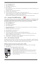
Operation instructions • english
Gebrauchsanweisung • deutsch
Gebruiksaanwijzing • nederlands
Manuel d’utilisation • français
1923420E
0547
KEMPPI PRO EVOLUTION
MXE
CONTENTS
1.
PREFACE ........................................................................................................................ 3
2.
3.
4.
5.
1.1.
1.2.
Introduction ....................................................................................................................... 3
Product introduction .......................................................................................................... 3
1.3.
Operation safety ................................................................................................................ 4
2.1.
Installation instructions ...................................................................................................... 4
2.2.
MXE quick guide ............................................................................................................... 5
1.2.1.
Main functions of the MXE-panel .................................................................................... 3
INSTALLATION ............................................................................................................... 4
2.1.1.
2.1.2.
MXE delivery package contains ...................................................................................... 4
MXE installation .............................................................................................................. 5
2.2.1.
2.2.2.
2.2.3.
2.2.4.
2.2.5.
2.2.6.
2.2.7.
MIG/MAG welding ........................................................................................................... 5
MMA welding ................................................................................................................... 5
Synergic MIG/MAG welding, 1-MIG ................................................................................ 5
Synergic PulsedMIG welding .......................................................................................... 6
Use of memory channels ................................................................................................ 6
SETUP function ............................................................................................................... 7
1-MIG and PulsedMIG synergic curves .......................................................................... 7
MXE FUNCTIONS ......................................................................................................... 12
3.1.
3.2.
3.3.
Welding process selection .............................................................................................. 12
MIG process selection..................................................................................................... 12
1-MIG/PulsedMIG synergic curves selection .................................................................. 12
3.4.
3.5.
3.6.
3.7.
3.8.
3.9.
3.10.
Basic controls, basic displays, Weld Data ....................................................................... 13
Welding dynamics control ............................................................................................... 13
Selections for main controls ............................................................................................ 13
Double pulse ................................................................................................................... 14
MIG auxiliary functions .................................................................................................... 14
Testing the gas feed ........................................................................................................ 14
MXE memory channels, MEMORY ................................................................................. 15
3.11.
Presettings of welding parameters, SETUP .................................................................... 16
3.3.1.
1-MIG or PulsedMIG synergic curve is selected as follows .......................................... 13
3.10.1.
Following parameters are stored into memory .............................................................. 15
3.11.1.
3.11.2.
3.11.3.
SETUP functions in MXE .............................................................................................. 16
Changing of parameters in SETUP change mode ........................................................ 18
Storing SETUP parameters into MXE memory channels .............................................. 18
DISPOSAL OF THE MACHINE..................................................................................... 19
TERMS OF GUARANTEE............................................................................................. 19
2 – KEMPPI PRO EVOLUTION, MXE / 0547
© KEMPPI OY
1.
PREFACE
1.1.
INTRODUCTION
Congratulations on having purchased this product. Properly installed Kemppi products should
prove to be productive machines requiring maintenance at only regular intervals. This manual
is arranged to give you a good understanding of the equipment and its safe operation. It also
contains maintenance information and technical specifications. Read this manual from front to
back before installing, operating or maintaining the equipment for the first time. For further
information on Kemppi products please contact us or your nearest Kemppi distributor.
The specifications and designs presented in this manual are subject to change without prior
notice.
In this document, for danger to life or injury the following symbol is used:
Read the warning texts carefully and follow the instructions. Please also study the Operation
safety instructions and respect them when installing, operating and servicing the machine.
1.2.
PRODUCT INTRODUCTION
MXE is a control panel which is designed for the PROMIG 501, PROMIG 511 and PROMIG
530 wire feeders. Operations of the MXE panel are versatile and very suitable for MIG/MAG
and PulsedMIG in the most demanding welding environment. MMA welding is also possible.
MXE panel is part of the KEMPPI PRO product range.
This manual describes installation, functions and use of the MXE panel. Installation and functions of other units of welding set such as power source, cooling unit and wire feeder, are described in manuals and installation instructions delivered with those units.
1.2.1. Main functions of the MXE panel
1
3
2
6
•
•
•
•
•
•
•
•
•
•
10
13
12
11
8
14
4
5
9
7
Selection of welding process: MMA (1), MIG 2T, MIG 4T (2)
Selection of MIG process (3): MIG/MAG, synergic MIG/MAG, synergic PulsedMIG
Material, gas and wire diameter selections for synergic welding (10)
Controls and displays of main welding parameters: wire feed speed or MMA current (4), voltage (5),
welding dynamics (8), plate thickness display (6) in synergic programs
Selection for controls (7): local controls, gun remote control unit, remote control unit
Storing of welding situations (MIG/MAG, PulsedMIG) (9): 20 channels to store welding parameters
Special features of MIG/MAG and PulsedMIG processes selected from panel (11): creep start, hot
start, spot weld timer, crater filling
Checking the shielding-gas flow
Using double pulse in PulsedMig welding
Parameter presettings of MIG/MAG, 1-MIG and PulsedMIG welding can be changed by using
SETUP function (14)
© KEMPPI OY
KEMPPI PRO EVOLUTION, MXE / 0547 – 3
1.3.
OPERATION SAFETY
Please study these Operation safety instructions and respect them when installing, operating and
servicing the machine.
Welding arc and spatters
Welding arc hurts unprotected eyes. Be careful also with reflecting arc flash. Welding arc and
spatter burn unprotected skin. Use safety gloves and protective clothing.
Danger for fire or explosion
Pay attention to fire safety regulations. Remove flammable or explosive materials from welding place. Always reserve sufficient fire-fighting equipment on welding place. Be prepared for
hazards in special welding jobs, eg. for the danger of fire or explosion when welding container
type work pieces. Note! Fire can break out from sparks even several hours after the welding
work has been finished!
Mains voltage
Never take welding machine inside a work piece (eg. container or truck). Do not place welding
machine on a wet surface. Always check cables before operating the machine. Change defect
cables without delay. Defect cables may cause an injury or set out a fire. Connection cable must
not be compressed, it must not touch sharp edges or hot work pieces.
Welding power circuit
Isolate yourself by using proper protective clothing, do not wear wet clothing. Never work on a
wet surface or use defect cables. Do not put MIG-gun or welding cables on welding machine or
on other electric equipment. Do not press MIG-gun switch, if the gun is not directed towards a
work piece.
Welding fumes
Take care that there is sufficient ventilation during welding. Take special safety precautions
when welding metals which contain lead, cadmium, zinc, mercury or beryllium.
2.
INSTALLATION
2.1.
INSTALLATION INSTRUCTIONS
2.1.1. MXE delivery package contains:
A. MXE control panel
B. This users manual
4 – KEMPPI PRO EVOLUTION, MXE / 0547
© KEMPPI OY
2.1.2. MXE installation
a)
Put other units of the welding equipment; PRO power source, PROMIG wire feeder, eventual
PROCOOL water cooling unit, into operation condition before mounting the MXE panel.
b) Make sure that no supply voltage has been connected to the PROMIG, main switch of power
source OFF.
c) Mount the MXE panel to the PROMIG wire feeder according to figure on the previous page.
2.2.
MXE QUICK GUIDE
1
3
2
6
11
10
13
12
8
4
14
5
9
7
2.2.1. MIG/MAG welding
a)
b)
b)
c)
d)
e)
f)
Select MEMORY OFF (9)
Select FACTORY (14)
Select MIG 2T or MIG 4T (2)
Select MIG (3)
If needed, select gun or remote control (7)
If needed, select creep start (11)
Adjust wire feed speed (4), welding voltage (5) and welding dynamics as needed (8)
Weld and adjust wire speed and voltage when necessary from controls 4 and 5.
2.2.2. MMA welding
a) Select MEMORY OFF (9)
b) Select FACTORY (14)
c) Select MMA welding (1). Note! Power source is turned on and open circuit voltage will be
switched on.
d) Select remote control if needed (7)
e) Adjust MMA welding current as needed (4)
f) With welding dynamics control (8) you can optimize welding result with different electrode
types.
Weld and adjust current when necessary from control 4.
2.2.3. Synergic MIG/MAG welding, 1-MIG
With the synergic MIG/MAG welding the power control is easy. Welding power is controlled
from one control (4) from minimum values to maximum values and the arc is kept stable. Synergic MIG/MAG welding requires selection of a correct material curve before welding.
© KEMPPI OY
KEMPPI PRO EVOLUTION, MXE / 0547 – 5
a)
b)
c)
d)
e)
Select MEMORY OFF (9).
Select FACTORY (14).
Select MIG 2T or MIG 4T (2).
Select 1-MIG (3).
Select material curve from selection block 10 by selecting filler wire material, shielding gas and
filler wire diameter.
f) If needed, select remote or gun control (7).
g) If needed, select creep start (11) .
h) You can, if needed, select hot start and/or crater filling function (11).
i) Adjust welding power (4), arc length (5) and welding dynamics as needed (8). In welding power
control see also display for guidelines of plate thickness (6).
Weld and adjust welding power and arc length when necessary from controls 4 and 5.
2.2.4. Synergic PulsedMIG welding
Quick pulsing of the power source in synergic PulsedMIG welding produces a welding process with
controlled and spatterfree filler material transfer into weld piece. Welding power is controlled from
one control (4) from minimum values to maximum values and the arc is kept stable. Synergic
PulsedMIG welding requires selection of a correct material curve before welding.
a) Select MEMORY OFF (9).
b) Select FACTORY (14).
c) Select MIG 2T or MIG 4T (2).
d) Select Pulsed MIG (3).
e) Select material curve from selection block 10 by selecting filler wire material, shielding gas
and filler wire diameter.
f) If needed, select remote or gun control (7).
g) Select double pulse, if necessary (12).
h) If needed, select creep start (11).
i) You can if necessary select hot start or/and crater filling function (11).
j) Adjust welding power (4) and arc length (5) as needed. In welding power control see also
display for guidelines of plate thickness (6).
k) Weld and adjust welding power and arc length when necessary from controls 4 and 5.
l) ”Top Current”, control of pulse height in SETUP.
2.2.5. Use of memory channels
The MXE panel has 20 memory channels into which you can store MIG/MAG, 1-MIG and PulsedMIG welding situations. Panel selections as well as adjustment potentiometer values are stored into
memory. It is not possible to store MMA welding values into memory channels.
Welding situation storing into memory, SET + SAVE
a) Select settings and control values with your MIG process; MIG, 1-MIG or pulsed MIG.
b) Select SET (9).
c) Select the memory channel with CH- and CH+ keys.
d) Weld and adjust values if needed.
e) Store the welding situation with SAVE key.
f) By pressing the keys simultaneously (45), it is possible to go directly
from OFF mode to ON mode and store the currently welded values
without repeating the above steps a - e.
g) By pressing the keys simultaneously (42), you go over from ON mode
directly to OFF mode.
9
45
42
6 – KEMPPI PRO EVOLUTION, MXE / 0547
© KEMPPI OY
Use of stored welding situations, ON
a) Select ON (9).
b) Select the memory channel with CH- and CH+ keys.
c) Weld and carry out if necessary fine control for voltage/arc length from panel potentiometer (5)
or from remote control in case you have selected remote control mode (7).
2.2.6. SETUP function
With SETUP function users can change many of such MIG, 1-MIG and PulsedMIG welding parameters, for which there is no own adjustment on the panel. They can also be changed in ON and SET
mode of the memory function. Such parameters are for example pre and post gas times and hot-start.
With SETUP key (14) user can choose to use either factory parameters (FACTORY) or parameter
values changed by himself (USER). You can change the parameters in change state. To go over to
change state and return from it is done by pressing two keys simultaneously (11 and 14), see picture.
Control panel keys, which have function in SETUP mode are marked with blue color. Functions
of SETUP mode: S = parameter selection, +/- = value adjustment up/down, M = parameter value
storing into memory.
Activation of change state and return to welding state by
pressing two keys simultaneously (11 and 14).
14
11
M, storing into
memory
S, parameter selection
+/- , value adjustment
Moving back and forth in
SETUP functions
2.2.7. 1-MIG and PulsedMIG synergic curves
10
Material selection
Synergic PulsedMIG
Synergic MIG/MAG
Material display
Gas selection / display
Display of synergic
curve number
MIG process selection
Wire diameter selection / display
The MXE panel includes factory curves/programs for synergic welding of the most common
materials. The factory curve is selected from selection block (10), where you first select material, then gas and after that wire diameter, all these depending on filler wire and shielding gas
type you are using. Material selection is divided into 4 groups. Fe group: iron-based filler wires,
Al group: aluminium-based filler wires, Ss group: stainless filler wires and X group: special
wires. Synergic welding functions are marked with red colour. Enclosed tables for 1-MIG and
PulsedMIG synergic curves:
© KEMPPI OY
KEMPPI PRO EVOLUTION, MXE / 0547 – 7
8 – KEMPPI PRO EVOLUTION, MXE / 0547
© KEMPPI OY
Ss group
Fe group
display
diameter
1.2
1.6
0.8
205
206
211
0.9
160
1
1.4
156
0.9
1.2
155
203
1
154
202
1.2
153
0.8
1.2
201
1.2
152
0.9
122
151
0.8
117
121
0.9
1.6
115
1.6
1
1.2
113
150
0.9
127
0.8
111
112
1
Fe
1.6
107
1.2
Fe
1.2
105
125
Fe
1
103
123
Fe
0.9
102
SS-316
SS-316
SS-316
SS-316
SS-316
SS-316
FEMC
FEMC
FEMC
FEFCb-
FEMC
FEFC
FEFCb
FEMC
Fe
Fe
Fe
Fe
Fe
Fe
Fe
Fe
Fe
Fe
0.8
101
Fe
Material
Wire
G 19 123 LSi
G 19 123 LSi
G 19 123 LSi
G 19 123 LSi
G 19 123 LSi
G 19 123 LSi
T 42 2 M M 3 H5
T 42 2 M M 3 H5
T 42 2 M M 3 H5
T 42 2 B M 3 H5
T 42 2 M M 3 H5
T 42 2 P M 1 HE
T 42 2 B M 3 H5
T 42 2 M M 3 H5
G 42 2 (C) M G3Si1
G 42 2 (C) M G3Si1
G 42 2 (C) M G3Si1
G 42 2 (C) M G3Si1
G 42 2 (C) M G3Si1
G 42 2 (C) M G3Si1
G 42 2 (C) M G3Si1
G 42 2 (C) M G3Si1
G 42 2 (C) M G3Si1
G 42 2 (C) M G3Si1
G 42 2 (C) M G3Si1
G 42 2 (C) M G3Si1
G 42 2 (C) M G3Si1
G 42 2 (C) M G3Si1
G 42 2 (C) M G3Si1
EN
ER 316 LSi
ER 316 LSi
ER 316 LSi
ER 316 LSi
ER 316 LSi
ER 316 LSi
E 71T-1
E 71T-1
E 71T-1
E 71T-5M
E 71T-1
E 71T-1
E 71T-5M
E 71T-1
ER70S-6
ER70S-6
ER70S-6
ER70S-6
ER70S-6
ER70S-6
ER70S-6
ER70S-6
ER70S-6
ER70S-6
ER70S-6
ER70S-6
ER70S-6
ER70S-6
ER70S-6
AWS
1.4430
1.4430
1.4430
1.4430
1.4430
1.4430
1.5130
1.5130
1.5130
1.5130
1.5130
1.5130
1.5130
1.5130
1.5130
1.5130
1.5130
1.5130
1.5130
1.5130
1.5130
1.5130
1.5130
1.5130
1.5130
1.5130
1.5130
1.5130
1.5130
W.-Nr.
SG X2 CrNiMo 19.12
SG X2 CrNiMo 19.12
SG X2 CrNiMo 19.12
SG X2 CrNiMo 19.12
SG X2 CrNiMo 19.12
SG X2 CrNiMo 19.12
-
-
-
SG B1 M2 Y4254
-
SG R1 C Y4643
SG B1 M2 Y4254
-
-
-
-
-
-
-
-
-
-
-
-
-
-
-
-
DIN
Filler material classification
SYNERGIC 1-MIG PROGRAMS
N:o
ArHEO2
Ar2CO2
Ar2CO2
Ar2CO2
Ar2CO2
Ar2CO2
CO2
Ar18CO2
CO2
Ar18CO2
Ar18CO2
Ar18CO2
Ar18CO2
Ar18CO2
Ar8CO2
Ar8CO2
Ar8CO2
Ar8CO2
Ar8CO2
CO2
CO2
CO2
CO2
CO2
Ar18CO2
Ar18CO2
Ar18CO2
Ar18CO2
Ar18CO2
Gas display
Ar+30%He+1%O2
Ar+2%CO2
Ar+2%CO2
Ar+2%CO2
Ar+2%CO2
Ar+2%CO2
CO2
Ar+18%CO2
CO2
Ar+18%CO2
Ar+18%CO2
Ar+18%CO2
Ar+18%CO2
Ar+18%CO2
Ar+8%CO2
Ar+8%CO2
Ar+8%CO2
Ar+8%CO2
Ar+8%CO2
CO2
CO2
CO2
CO2
CO2
Ar+18%CO2
Ar+18%CO2
Ar+18%CO2
Ar+18%CO2
Ar+18%CO2
Gas mixture
© KEMPPI OY
KEMPPI PRO EVOLUTION, MXE / 0547 – 9
Al group
1.6
1
1.2
323
1.2
295
321
1.2
293
305
0.9
292
1
1.2
286
1.2
1.2
285
303
1.2
276
301
1
1.2
1.2
270
275
1.2
269
273
1
0.9
268
255
263
1
1.2
254
1
253
1
243
1
1.2
235
1.2
1
233
245
0.9
232
244
1
222
1.2
0.9
216
225
1.6
215
223
1
1.2
213
0.9
212
Al-4043
AL-4043
Al-5356
Al-5356
Al-5356
FC-316LP
FC-308
FC-316
FC-2209
FC-309
FC-2209
FC-309L
SS-385
FC-316LP
FC-308L
FC-316
SS-385
SS-318
SS-318
SS-307
SS-318
SS-318
SS-307
SS-309
SS-309
SS-309
SS-309
SS-309
SS-309
SS-316
SS-316
SS-316
SS-316
-
-
-
-
-
T 19 12 3L P M/C 1
T 19 9L R M/C 3
T 19 12 3L M/C 3
T 22 9 3 N L R M/C 3
T 23 12L R M/C 3
T 22 9 3 N L R M/C 3
T 23 12L R M/C 3
G 20.25.2 CuLN
T 19 12 3L P M/C 1
T 19 9L R M/C 3
T 19 12 3L M/C 3
G 20.25.2 CuLN
G 19 12 3 NbSi
G 19 12 3 NbSi
G 18 8 MnSi
G 19 12 3 NbSi
G 19 12 3 NbSi
G 18 8 MnSi
G 23 12 LSi
G 23 12 LSi
G 23 12 LSi
G 23 12 LSi
G 23 12 LSi
G 23 12 LSi
G 19 123 LSi
G 19 123 LSi
G 19 123 LSi
G 19 123 LSi
ER 4043
ER 4043
ER 5356
ER 5356
ER 5356
E 316 LT-1
E 308 L
E 316 LT-1
E 2209TO-4
E 309 LT-0
E 2209TO-4
E 309 LT-0
ER 385
E 316 LT-1
E 308 L
E 316 LT-1
ER 385
ER 318
ER 318
ER 307 LSi
ER 318
ER 318
ER 307 LSi
ER 309 LSi
ER 309 LSi
ER 309 LSi
ER 309 LSi
ER 309 LSi
ER 309 LSi
ER 316 LSi
ER 316 LSi
ER 316 LSi
ER 316 LSi
3.2245
3.2245
3.3556
3.3556
3.3556
1.4430
1.4316
1.4430
1.4460
1.4459
1.4460
1.4459
1.4519
1.4430
1.4316
1.4430
1.4519
1.4576
1.4576
1.4370
1.4576
1.4576
1.4370
1.4332
1.4332
1.4332
1.4332
1.4332
1.4332
1.4430
1.4430
1.4430
1.4430
SG-AlSi5
SG-AlSi5
SG-AlMg 5
SG-AlMg 5
SG-AlMg 5
-
19 9 L
19 12 3 L
22 9 3 LR
-
22 9 3 LR
-
SG X2 CrNiMoCuN 20.25
-
19 9 L
19 12 3 L
SG X2 CrNiMoCuN 20.25
SG X5 CrNiMoNb 19 12
SG X5 CrNiMoNb 19 12
SG X 15 CrNiMn 18 8
SG X5 CrNiMoNb 19 12
SG X5 CrNiMoNb 19 12
SG X 15 CrNiMn 18 8
-
-
-
-
-
-
SG X2 CrNiMo 19.12
SG X2 CrNiMo 19.12
SG X2 CrNiMo 19.12
SG X2 CrNiMo 19.12
Ar
Ar
Ar
Ar
Ar
CO2
CO2
CO2
CO2
CO2
Ar18CO2
Ar18CO2
ArHEO2
Ar18CO2
Ar18CO2
Ar18CO2
Ar2CO2
ArHEO2
ArHEO2
ArHEO2
Ar2CO2
Ar2CO2
Ar2CO2
ArHEO2
ArHEO2
ArHEO2
Ar2CO2
Ar2CO2
Ar2CO2
ArHEO2
ArHEO2
ArHEO2
ArHEO2
Ar
Ar
Ar
Ar
Ar
CO2
CO2
CO2
CO2
CO2
Ar+18%CO2
Ar+18%CO2
Ar+30%He+1%O2
Ar+18%CO2
Ar+18%CO2
Ar+18%CO2
Ar+2%CO2
Ar+30%He+1%O2
Ar+30%He+1%O2
Ar+30%He+1%O2
Ar+2%CO2
Ar+2%CO2
Ar+2%CO2
Ar+30%He+1%O2
Ar+30%He+1%O2
Ar+30%He+1%O2
Ar+2%CO2
Ar+2%CO2
Ar+2%CO2
Ar+30%He+1%O2
Ar+30%He+1%O2
Ar+30%He+1%O2
Ar+30%He+1%O2
10 – KEMPPI PRO EVOLUTION, MXE / 0547
© KEMPPI OY
Ss group
Fe group
X group
0.8
0.9
0.9
1
1
0.8
402
403
404
406
407
408
CuAl 8
Cusi 3
Cusi 3
Cusi 3
Cusi 3
Cusi 3
Cusi 3
Al-5183
Al-4043
0.8
0.9
1
612
613
1.2
550
1.2
1.6
527
611
1.2
525
605
1
523
1
0.9
522
603
0.8
521
0.9
1.2
505
0.8
1
503
602
0.9
502
601
0.8
501
SS-316
SS-316
SS-316
SS-316
SS-316
SS-316
SS-316
FEMC
FE
FE
FE
FE
FE
FE
FE
FE
FE
G 19 123 LSi
G 19 123 LSi
G 19 123 LSi
G 19 123 LSi
G 19 123 LSi
G 19 123 LSi
G 19 123 LSi
T 42 2 M M 3 H5
G 42 2 (C) M G3Si1
G 42 2 (C) M G3Si1
G 42 2 (C) M G3Si1
G 42 2 (C) M G3Si1
G 42 2 (C) M G3Si1
G 42 2 (C) M G3Si1
G 42 2 (C) M G3Si1
G 42 2 (C) M G3Si1
ER 316 LSi
ER 316 LSi
ER 316 LSi
ER 316 LSi
ER 316 LSi
ER 316 LSi
ER 316 LSi
E 71T-1
ER70S-6
ER70S-6
ER70S-6
ER70S-6
ER70S-6
ER70S-6
ER70S-6
ER70S-6
ER70S-6
ER CuAl-A1
ER Cusi 3
ER Cusi 3
ER Cusi 3
ER Cusi 3
ER Cusi 3
ER Cusi 3
ER 5183
ER 4043
AWS
1.4430
1.4430
1.4430
1.4430
1.4430
1.4430
1.4430
1.5130
1.5130
1.5130
1.5130
1.5130
1.5130
1.5130
1.5130
1.5130
1.5130
2.0921
2.1461
2.1461
2.1461
2.1461
2.1461
2.1461
3.3548
3.2245
W.-Nr.
SG X2 CrNiMo 19.12
SG X2 CrNiMo 19.12
SG X2 CrNiMo 19.12
SG X2 CrNiMo 19.12
SG X2 CrNiMo 19.12
SG X2 CrNiMo 19.12
SG X2 CrNiMo 19.12
-
-
-
-
-
-
-
-
-
-
SG-CuAl 8
SG-CuSi3
SG-CuSi3
SG-CuSi3
SG-CuSi3
SG-CuSi3
SG-CuSi3
SG-AlMg4.5Mn
SG-AlSi5
DIN
Filler material classification
G 42 2 (C) M G3Si1
-
-
-
-
-
-
-
-
-
EN
PULSEDMIG PROGRAMS
0.8
1.2
400
1.6
display
diameter
333
Material
Wire
325
N:o
ArHEO2
ArHEO2
ArHEO2
Ar2CO2
Ar2CO2
Ar2CO2
Ar2CO2
Ar18CO2
Ar8CO2
Ar8CO2
Ar8CO2
Ar8CO2
Ar8CO2
Ar18CO2
Ar18CO2
Ar18CO2
Ar18CO2
Ar
Ar2CO2
Ar
Ar2CO2
Ar
Ar2CO2
Ar
Ar
Ar
Gas display
Ar+30%He+1%O2
Ar+30%He+1%O2
Ar+30%He+1%O2
Ar+2%CO2
Ar+2%CO2
Ar+2%CO2
Ar+2%CO2
Ar+18%CO2
Ar+8%CO2
Ar+8%CO2
Ar+8%CO2
Ar+8%CO2
Ar+8%CO2
Ar+18%CO2
Ar+18%CO2
Ar+18%CO2
Ar+18%CO2
Ar
Ar+2% CO2
Ar
Ar+2% CO2
Ar
Ar+2% CO2
Ar
Ar
Ar
Gas mixture
© KEMPPI OY
KEMPPI PRO EVOLUTION, MXE / 0547 – 11
X group
Al group
1.2
0.8
1
1
1
0.8
804
805
806
807
808
755
802
1.6
753
1.2
1.2
733
1.2
1.2
725
801
1.6
723
800
1
1.2
721
0.8
1
693
1.2
1
690
720
1.2
685
713
1
683
1.6
1.2
665
1.2
1
663
705
1.2
655
703
1
653
1
0.9
632
701
1
1.2
625
0.9
622
623
1.2
615
CuAl 8
CuAl 8
CuSi 3
CuSi 3
CuSi 3
CuSn
CuAl 8
NiCu 30
AL-1050
AL-1050
AL-4047
AL-4043
AL-4043
AL-4043
AL-4043
AL-5183
AL-5356
AL-5356
AL-5356
SS-385
SS-385
SS-409
SS-409
Inc-625
Inc-625
dUPLE
dUPLE
SS-309
SS-309
SS-309
SS-309
SS-316
-
-
-
-
-
-
-
-
-
-
-
-
-
-
-
-
-
-
-
G 20.25.2 CuLN
G 20.25.2 CuLN
G 23 12 LSi
G 23 12 LSi
-
-
G 22 9 3 LN
G 22 9 3 LN
G 23 12 LSi
G 23 12 LSi
G 23 12 LSi
G 23 12 LSi
G 19 123 LSi
ER CuAl-A1
ER CuAl-A2
ER Cusi 3
ER Cusi 3
ER Cusi 3
ER Cu
ER CuAl-A2
ER NiCu-7
ER 1100
ER 1100
ER 4047
ER 4043
ER 4043
ER 4043
ER 4043
ER 5183
ER 5356
ER 5356
ER 5356
ER 385
ER 385
ER 309 LSi
ER 309 LSi
ER NiCrMo-3
ER NiCrMo-3
ER 2209
ER 2209
ER 309 LSi
ER 309 LSi
ER 309 LSi
ER 309 LSi
ER 316 LSi
2.0921
2.0921
2.1461
2.1461
2.1461
2.1022
2.0921
2.4377
3.0259
3.0259
3.2585
3.2245
3.2245
3.2245
3.2245
3.3548
3.3556
3.3556
3.3556
1.4519
1.4519
1.4332
1.4332
2.4831
2.4831
1.4460
1.4460
1.4332
1.4332
1.4332
1.4332
1.4430
SG-CuAl 8
SG-CuAl 8
SG-CuSi3
SG-CuSi3
SG-CuSi3
SG-CuSn
SG-CuAl 8
-
SG-Al 99.5
SG-Al 99.5
SG-AlSi12
SG-AlSi5
SG-AlSi5
SG-AlSi5
SG-AlSi5
SG-AlMg4.5Mn
SG-AlMg 5
SG-AlMg 5
SG-AlMg 5
SG X2 CrNiMoCuN 20.25
SG X2 CrNiMoCuN 20.25
-
-
SG NiCr21 Mo9Nb
SG NiCr21 Mo9Nb
SG X2 CrNiMo 22.9.3
SG X2 CrNiMo 22.9.3
-
-
-
-
SG X2 CrNiMo 19.12
Ar
Ar
Ar2CO2
Ar
Ar
Ar50HE
Ar
Ar
Ar
Ar
Ar
Ar
Ar
Ar
Ar
Ar
Ar
Ar
Ar
ArHEO2
ArO2
Ar2CO2
Ar2CO2
ArHEO2
ArHEO2
ArHEO2
ArHEO2
ArHEO2
Ar2CO2
Ar2CO2
Ar2CO2
ArHEO2
Ar
Ar
Ar+2%CO2
Ar
Ar
Ar+50%He
Ar
Ar
Ar
Ar
Ar
Ar
Ar
Ar
Ar
Ar
Ar
Ar
Ar
Ar+30%He+1%O2
Ar+2%CO2
Ar+2%CO2
Ar+2%CO2
Ar+30%He+1%O2
Ar+30%He+1%O2
Ar+30%He+1%O2
Ar+30%He+1%O2
Ar+30%He+1%O2
Ar+2%CO2
Ar+2%CO2
Ar+2%CO2
Ar+30%He+1%O2
3.
MXE FUNCTIONS
3.1.
WELDING PROCESS SELECTION
1
2
3
1.
2.
3.
4.
MMA selection, power source is switched on open circuit voltage.
MIG welding with 2 sequence start switch function, MIG 2T.
MIG welding with 4 sequence start switch function, MIG 4T.
Selecting key for MIG 2T / MIG 4T.
4
3.2.
MIG PROCESS SELECTION
5
6
7
8
6.
7.
8.
5.
Synergic PulsedMIG welding: Welding process where by pulsing the
welding current is produced a controlled, spatterfree filler material transfer into weld piece. Pulse parameters of power source are automatically
changed according to wire feed speed (synergy). This enables welding
power level control by using only one control knob. Dependence of pulse
parameters on wire feed speed is defined by selecting synergic curve for
filler wire and gas you are using.
Synergic MIG/MAG welding (1-MIG): MIG welding, where other parameter values are
automatically changed according to wire feed speed. This enables welding power level
control by using only one control knob. Dependence of welding parameters on wire feed
speed is defined by selecting synergic curve for filler wire and gas you are using.
MIG/MAG welding with independent wire feed speed and voltage controls.
MIG process selection key; MIG/MAG, 1-MIG, PulsedMIG
3.3.
1-MIG / PULSEDMIG SYNERGIC CURVES SELECTION
12
11
13
10
14
16
9
15
9.
10.
11.
12.
MIG process selection key.
Indicator LED of synergic MIG/MAG welding.
Indicator LED of synergic PulsedMIG welding.
Selection keys of material groups:
Fe: iron-based filler wires, also flux cored filler wires.
Al: aluminium-based filler wires, for example AlMg, AlSi.
Ss: stainless filler wires, for example AlSi 316L.
X: special wires, for example CuAl8, NiCu30, CuSi3.
13. Display for selected filler wire material.
14. Selection and display for shielding gas you are using.
15. Selection key and display for wire diameter.
16. Program numerical display.
Note! Synergic functions are marked with red colour.
12 – KEMPPI PRO EVOLUTION, MXE / 0547
© KEMPPI OY
3.3.1. 1-MIG or PulsedMIG synergic curve is selected as follows
a) Select 1-MIG or PulsedMIG.
b) Select material group. You get from the material group in question the curve with which
was started last. If the selected material is not the right one, you can browse materials in the
material group by re-pressing the material group selection key.
c) Select shielding gas. Only gas selections possible for the material in question are displayed.
d) Select wire diameter. Only diameters possible for the filler wire/gas selection in question
can be selected. The unit remembers (MEMORY) last selections from each material group
(material, gas, wire diameter) separately at 1-MIG and PulsedMIG.
3.4.
BASIC CONTROLS, BASIC DISPLAYS, WELD DATA
19
22
18
21
17
20
17. Control for wire feed speed in MIG/MAG, welding
power in 1-MIG and PulsedMIG, and welding current in MMA.
18. Display for wire feed speed or MMA current.
19. Informative plate thickness display in 1-MIG and
PulsedMIG for horizontal vertical fillet weld. During
welding true welding current display.
20. Control for welding voltage (MIG/MAG), or arc
length (1-MIG and Pulsed MIG).
21. Display of welding voltage set value with MIG/MAG and 1-MIG. Set value display for arc
length with Pulsed-MIG, range -9...0...9. During welding pole voltage of power source is
displayed. Display is also used as display of welding dynamics control, -9...0...9.
22. Pressing the WELD DATA key restores to displays those values of wire feed speed, welding
current and welding voltage which were used when welding was stopped.
3.5.
WELDING DYNAMICS CONTROL
23
23. Control for MIG/MAG, 1-MIG and MMA welding dynamics. Control
value -9...0...9 is displayed in display 21. Welding dynamics control
influences welding stability and spatter amount. Zero position is recommended as basic setting. Values -9...-1, softer arc in order to reduce spatter
amount. Values 1...9, harder arc in order to increase stability, and when
using 100 % CO2 shielding gas in steel welding.
3.6. SELECTIONS FOR MAIN CONTROLS
26
25
24
27
24. Local control, main controls are made from panel potentiometers 17 and 20.
25. Gun control, wire feed speed or welding power controls are made from
control unit RMT10, which is mounted to PMT MIG gun. Welding voltage
or arc length controls are made from panel potentiometer 20.
26. Remote control, main controls are made from control unit R20 connected to
main wire feeder or from PROMIG 100 sub-feeder.
27. Control selection key.
Note! You cannot select remote control mode or gun remote control mode if the
control unit is not connected to the welding equipment.
© KEMPPI OY
KEMPPI PRO EVOLUTION, MXE / 0547 – 13
3.7. DOUBLE PULSE
12
3.8.
The double-pulse function operates only with PulsedMIG welding.
Wire feed speed can be regulated max. 2.5 m/min above and below the
relected wire feed speed. At the same time, the synergic welding parameters are changed to match the current wire feed speed. The purpose
of the function is to create a suitable protrusion and good appearance
in the weld. It also improves the controllability of weld pool in position
welding.
MIG AUXILIARY FUNCTIONS
30. Creep start, MIG/MAG, 1-MIG, PulsedMIG: Creep start is used for
smooth start for example in welding with high wire feed speeds. In
30
start the wire feed speed is lower than set value until the wire touches
31
the weld piece and current starts flowing. Note! If the wire does not
32
touch the weld piece within 0.6 seconds, wire feed speed goes over to
set value. When needed you can change lower wire feed speed level on
33
creep start and also wire feed speed upslope with SETUP functions.
31. Hot start, spot weld timer:
Hot start function is used to reduce start faults in welding of well heat conductive materials
such as aluminium. Hot start is in use with 1-MIG and PulsedMIG. In 4T mode hot start the
time is set with switch function (see picture), in 2T mode the time is set with the parameter
of SETUP function. Hot start level can be changed with SETUP function when needed.
Spot weld timer is normally switched off. The timer is switched on with SETUP function
by setting the spot weld time as different from zero, and correspondingly switched off by
setting the spot weld time as zero. Spot weld time is switched on with 2T switch function,
in which case hot start is selected (the LED is on) but not in use when spot weld time is
over zero. Hot start has to be selected in order to use spot weld. Current during spot weld
time is the same as hot start current.
32. Crater filling, 1-MIG and PulsedMIG:
Crater filling is used to reduce weld defects caused by end crater. With 4T switch function
at the weld end you get, during pressing gun’s start switch, a steplessly decreasing welding
power, which fills end crater in a controlled way. With 2T mode the decreasing time is constant. Decreasing speed of welding power and decreasing time can be changed with SETUP
function when needed.
33. Selecting key for MIG auxiliary functions.
Auxiliary functions can be switched on independently from each other, either together or
separately both with 4T and 2T.
Note! With longer creep start times creep start and hot start cannot be switched on at the
same time.
Creep start, 30
Wire feed speed/power
Start switch
Welding current
3.9.
Hot-start, 31
Crater filling, 32
Wire feed speed/power/
welding current
Start switch 4T
TESTING THE GAS FEED
By pressing the gas-feed test key, you can make the shielding gas flow without starting the power source or the wire feed. This enables the measuring of the gas flow
with an external measuring device.
The gas flow will cease when you press the same key again or the gun trigger. If you
do not press the key again, gas flow will cease automatically in 20 seconds.
14 – KEMPPI PRO EVOLUTION, MXE / 0547
© KEMPPI OY
3.10. MXE MEMORY CHANNELS, MEMORY
The MXE panel has 20 memory channels into which you can be store MIG/MAG, 1-MIG and
PulsedMIG welding situations. Control potentiometer values as well as function selections are
stored into memory. You cannot store MMA welding values into memory channels.
3.10.1. Following parameters are stored into memory
41 – Wire feed speed and welding voltage (MIG/MAG)
36
35
34
37
42
45
38
40 – Welding power and arc length (1-MIG, PulsedMIG)
– Synergic curve selections (1-MIG, PulsedMIG)
39
– MIG dynamics (MIG/MAG, 1-MIG)
– MIG 2T / MIG 4T selections
– Creep start selection
– Hot start and crater filling selections (1-MIG, PulsedMIG)
– FACTORY / USER parameter selections
Operation modes of memory function are selected with key 37. Operation modes are OFF (34):
normal welding without memory functions. ON (35): welding with welding values stored into
memory channels. SET (36): mode where you can store welding values into memory channels
by pressing on memory key SAVE (41). Memory channel is selected by CH- (38) and CH+ (39)
keys. Number of selected channel is displayed in screen 40.
In SET mode (36) blinking indicator LED shows that no welding values are stored into the
channel in question. When needed, you can clear the memory channel by simultaneous pressing
(42) of keys for mode selection (37) and CH- (38). Before clearing you can check the values
stored into channel by going over for a moment to ON state (35).
In ON state you can select only those channels with stored values. Fine control of stored channels for welding voltage (MIG/MAG) or for arc length (1-MIG, PulsedMIG) is made from
potentiometer 43. During welding you can change channels if the MIG process (MIG, 1-MIG,
PulsedMIG) remains the same. Also 1-MIG and PulsedMIG synergic curve selection should be
the same in the channels in question.
Selection of memory channels 1-5 can be transferred to remote control unit R20, connected
to the PROMIG or to gun remote control unit RMT10 of the PMT MIG gun. Change-over to
remote control of channels is made in ON state by simultaneous pressing (44) of CH+ (39) and
control selection (27) keys. When using R20 control unit both channel selection and fine control
are transferred to potentiometers of the control unit. When using RMT10 control unit the channel selection is transferred to RMT10 and fine control remains in the panel potentiometer (43).
Remote selection of memory channels is indicated by blinking remote control or gun remote
control indicator LEDs. Exit from remote control in the same way by simultaneous pressing
(44). You can go directly from OFF to SET mode by simultaneous pressing (45) of keys 37 and
39 (= direct storing of currently welded values into memory). You can go directly from ON to
OFF mode by simultaneous pressing (42) of keys 37 and 38.
channel selection
1, 2, 3, 4, 5
43
fine control
channel selection
1, 2, 3, 4, 5
44
© KEMPPI OY
27
KEMPPI PRO EVOLUTION, MXE / 0547 – 15
3.11. PRESETTINGS OF WELDING PARAMETERS, SETUP
With SETUP function the user can change such parameters of MIG, 1-MIG and PulsedMIG,
for which there is no own control on the panel. Such parameters are for example pre-, post gas
time and hot start. Parameters are different for every MIG process, which means that you can set
independently your own parameters for MIG, 1-MIG and PulsedMIG. SETUP keys are marked
with blue colour.
Modes of SETUP function:
a) FACTORY mode: Use the so called factory settings of welding parameters.
b) USER mode: Use welding parameters changed by the user.
c) SETUP change mode: Mode in which parameters are changed and stored into memory.
3.11.1. SETUP functions in MXE
16 – KEMPPI PRO EVOLUTION, MXE / 0547
© KEMPPI OY
Name in
display
MIG/
MAG
1MIG
Pulsed
MIG
Factory
value
Pre gas time 0-9.9 s
PrEGAS
X
X
X
0
Post gas time 0-9.9 s
POStGAS
X
X
X
1.0
Gas flow after welding
Creep start 10-99%
CrEEP S
X
X
X
50%
% of wire feed speed
Hot start
-50…0…+70%
HOt-StA
X
X
40%
% of welding power, -50% is cold
and +70% is hot
Hot start 2T (*
0....9,9 s
Hot-2tt
X
X
1.2 s
Adjustment of Hot start time
with 2T
Spot welding (**
0.0 ... 9.9 s
SPOt-2t
X
X
0.0 s
Spot welding in use, when Hot
start is selected and SPOt-2t is
0.1 ... 9.9 s. Welding power is
same as Hot start`s.
X
X
0
Rising time to welding power,
1 is shorter, 99 is longer
Creep start upslope
0…99
UPSLOPE
X
Explanation
Gas flow before welding, works
with 2T
Crater filling
1…99
CrAtErF
X
X
15
Fall time to crater slope,
1 is shorter, 99 is longer
Crater slope
CrAtESL
X
X
0
End level of welding power,1%
X
X
0
Length of start pulse
X
0
MXE-function, adjustment of
pulse current
X
X
0
Length of wire after stop welding
e.g. Al <0, Fe > 0
X
X
0
Expands arc length range (knob)
0…99%
min current, 99% max current
Start current
–9…0…+9
StArt C
Top current
–10…+15%
top-Cur
X
Post current time
–99…0…+99
POStCUr
Control range of arc
length –50…0…99%
ArCLEnG
Douple pulse
amplitude
0,1 ...2,5m/min
dPULS-A
X
Douple pulse
frequency
0,1 ... 3,0 Hz
dPULS-F
X
2 Hz
X
X
1.4
X
X
Calibration voltage
0…9.9 V
CAL
Restoring of factory
settings
rEStOrE
FAC ALL
X
X
1,5 m/min Wire feed variation in douple
pulse
Frequency variation in douple
pulse
1.4 is for general use, position of
arc length range can be moved
within 0…9.9V
Restores factory settings to User
parametres
(* Since Promig program version 0A5
(** Since Promig program version 0A6
© KEMPPI OY
KEMPPI PRO EVOLUTION, MXE / 0547 – 17
3.11.2. Changing of parameters in SETUP change mode
a)
5
6
7
8
Select the MIG process, MIG/MAG (7), 1-MIG (6) or PulsedMIG
(5), the parameters of which you want to change.
b) Go to SETUP change state by simultaneous pressing 50 (keys 33 and
49).
c) Select the parameter to be adjusted with key 51. Parameter names are
to be seen in display 52 and parameter value in display 53.
d) Adjust parameter value upwards (+) or downwards (-) with keys 54.
e) Store the adjusted value into memory with key 55.
f)
47
48
49
50
Factory value of selected parameter can be checked by
going over briefly to FACTORY mode 47, in which case
factory value of parameter in question is displayed in 53.
g) Factory values of all parameters for selected MIG process
can be copied as USER parameter values by selecting
as parameter RESTORE FAC ALL and by pressing on
memory storing key 55.
h) Go back to weld mode by another simultaneous pressing 50
(keys 33 and 49).
55
51
5
6
7
52
53
54
3.11.3 Storing SETUP parameters into MXE memory channels
a) Select the settings and control values with the MIG process you are using, MIG/MAG (7),
1-MIG (6) or PulsedMIG (5).
b) Select SET mode of memory function by pressing key 37.
c) Choose the memory channel by pressing CH- (38) or CH+ (39).
d) Store the settings by pressing the SAVE key (41). If the memory channel is empty (the LED
is blinking), the SETUP parameters cannot be stored in memory function.
e) Go over to SETUP change state by simultaneous pressing (50) of keys 33 and 49.
f) Select the parameter to be controlled with key 51.
g) Adjust the parameter value up (+) or down (-) by pressing key 54.
h) Store the adjusted parameter into memory with key 55.
i) Return to memory function by another pressing (50).
j) Start welding, adjust the values if needed and store with SAVE key.
k) Leave SET function mode by pressing 37.
18 – KEMPPI PRO EVOLUTION, MXE / 0547
© KEMPPI OY
4. DISPOSAL OF THE MACHINE
Do not dispose of electrical equipment together with normal waste!
In observance of European Directive 2002/96/EC on Waste Electrical and Electronic
Equipment and its implementation in accordance with national law, electrical equipment
that has reached the end of its life must be collected separately and returned to an
environmentally compatible recycling facility. As the owner of the equipment, you should
get information on approved collection systems from our local representative.
By applying this European Directive you will improve the environment and human
health!
5. TERMS OF GUARANTEE
Kemppi Oy provides a guarantee for products manufactured and sold by them if defects in
manufacture and materials occur. Guarantee repairs must be carried out only by an Authorised
Kemppi Service Agent. Packing, freight and insurance costs to be paid by orderer. The guarantee is
effected on the date of purchase. Verbal promises which do not comply with the terms of guarantee
are not binding on guarantor.
Limitations on guarantee
The following conditions are not covered under the terms of guarantee: defects due to natural wear
and tear, non-compliance with operating and maintenance instructions, connection to incorrect or
faulty supply voltage (including voltage surges outside equipment spec.), incorrect gas pressure,
overloading, transport or storage damage, fire of damage due to natural causes i.e. lightning or
flooding.
This guarantee does not cover direct or indirect travelling costs, daily allowances or accommodation.
Note: Under the terms of guarantee, welding torches and their consumables, feeder drive rolls and
feeder guide tubes are not covered. Direct or indirect damage due to a defective product is not
covered under the guarantee. The guarantee is void if changes are made to the product without
approval of the manufacturer, or if repairs are carried out using non-approved spare parts.
The guarantee is also void if repairs are carried out by non-authorised agents.
Undertaking guarantee repairs
Guarantee defects must be informed to Kemppi or authorised Kemppi Service Agents within the
guarantee period. Before any guarantee work is undertaken, the customer must provide proof of
guarantee or proof of purchase, and serial number of the equipment in order to validate the guarantee.
The parts replaced under the terns of guarantee remain the property of Kemppi.
Following the guarantee repair, the guarantee of the machine or equipment, repaired or replaced,
will be continued to the end of the original guarantee period.
© KEMPPI OY
KEMPPI PRO EVOLUTION, MXE / 0547 – 19
KEMPPI OY
PL 13
FIN – 15801 LAHTI
FINLAND
Tel (03) 899 11
Telefax (03) 899 428
www.kemppi.com
KEMPPIKONEET OY
PL 13
FIN – 15801 LAHTI
FINLAND
Tel (03) 899 11
Telefax (03) 7348 398
e-mail: [email protected]
KEMPPI SVERIGE AB
Box 717
S – 194 27 UPPLANDS VÄSBY
SVERIGE
Tel (08) 590 783 00
Telefax (08) 590 823 94
e-mail: [email protected]
KEMPPI NORGE A/S
Postboks 2151, Postterminalen
N – 3103 TØNSBERG
NORGE
Tel 33 34 60 00
Telefax 33 34 60 10
e-mail: [email protected]
KEMPPI DANMARK A/S
Literbuen 11
DK – 2740 SKOVLUNDE
DANMARK
Tel 44 941 677
Telefax 44 941 536
e-mail:[email protected]
KEMPPI BENELUX B.V.
Postbus 5603
NL – 4801 EA BREDA
NEDERLAND
Tel +31 (0)76-5717750
Telefax +31 (0)76-5716345
e-mail: [email protected]
KEMPPI (UK) Ltd
Martti Kemppi Building
Fraser Road
Priory Business Park
BEDFORD, MK443WH
ENGLAND
Tel 0845 6444201
Fax 0845 6444202
e-mail: [email protected]
KEMPPI FRANCE S.A.
65 Avenue de la Couronne des Prés
78681 EPONE CEDEX
FRANCE
Tel (01) 30 90 04 40
Telefax (01) 30 90 04 45
e-mail: [email protected]
KEMPPI GmbH
Otto – Hahn – Straße 14
D – 35510 BUTZBACH
DEUTSCHLAND
Tel (06033) 88 020
Telefax (06033) 72 528
e-mail:[email protected]
KEMPPI SP. z o.o.
Ul. Piłsudskiego 2
05-091 ZA¸BKI
Poland
Tel +48 22 781 6162
Telefax +48 22 781 6505
e-mail: [email protected]
KEMPPI WELDING
MACHINES AUSTRALIA PTY LTD
P.O. Box 404 (2/58 Lancaster Street)
Ingleburn NSW 2565, Australia
Tel. +61-2-9605 9500
Telefax +61-2-9605 5999
e-mail: [email protected]
www.kemppi.com
Ver. 9