1
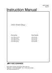
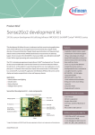
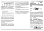
EUREKA E1206
EUREKA: Longitudinal Time Code Codec IC
EUREKA is the first of a series of integrated Time Code related devices developed by Hinton
Instruments to meet the requirements of the audio and video industries for high performance
reading and generation of SMPTE and EBU Time Code signals.
EUREKA has been designed as a Coder/Decoder to translate FM encoded Time Code to and
from separate Data and Clock signals suitable for a general purpose USART in synchronous
mode. Although orientated towards the Zilog Z8530 SCC and its derivatives (including Z80SIO, Z181 and Z182) any USART with Bisync capability may be used. Particular attention
has been paid to allow interfacing to Macintosh compatible MiniDIN serial ports and also for
microprocessor-less applications. Many useful status signals are provided as well as two onboard
crystal oscillators requiring only the addition of passive components.
The Codec/USART combination has several advantages over conventional bus interfaced
devices. It is less complicated and so more reliable and cheaper than integrating the whole frame
register and then interfacing to a generalised bus and interrupt structure. As microprocessors get
faster and more highly integrated EUREKA will not be rendered obsolete.
EUREKA is implemented in 1 micron CMOS FPGA technology which is second sourced and
widely available. There are and will be no problems in supplying any quantity from one to
thousands and no concerns about future availability, unlike single sourced ASICs.
Software support and customised versions can be provided if required.
EUREKA has the following features:
• Reads Longitudinal Time Code in the range 1/100th to 300 times playspeed (in
practice limited by analogue circuitry and signal levels).
• Decodes Time Code into signals suitable for clocking into USART or shift registers
directly.
• Encodes Time Code NRZ data generated by USART or counters into FM signal.
• Provides Oscillators and Dividers configurable in several useful ways.
• Provides pulses for Frame Sync word recognition and Change of Direction.
• Provides status of Direction and Slow Code.
• Provides clock at Eighth Frame rate for use in sub-frame accurate automation.
• Low Power consumption.
• 44 pin PLCC package for small size and surface mounting or socketing.
Evaluation samples and application notes £45GB, £30GB/10+, £20GB/100+(+VAT in EEC).
Scheduled quantities, single-product or multi-product licences negotiable.
For further information contact Graham Hinton:
Tel: Int + 44 1373 451927
EUREKA E1206 Specification
General Description
EUREKA comprises the following sections:
Master Oscillator (normally used with 12.288MHz crystal) with ÷2, ÷4,
÷6, ÷8 and ÷128 outputs.
Auxiliary Oscillator with ÷2 (squarewave)output.
General purpose Divide by 2 stage.
FM Encoder stage for Time Code Generation.
Selectable Bit Clock Divider for Digital Audio, SMPTE, EBU and Film
rates.
High performance wideband Time Code Reader Data/Clock Extractor
with Frame Sync Word Recogniser and status outputs. This stage has
superior detection and locking characteristics for coping with the
extreme demanding requirements of jog editing and video fast forward.
EUREKA requires only the discrete oscillator components and analogue
line buffering to make a complete Time Code Reader providing signals
suitable for clocking into either a frame register or a USART. A Time
Code Generator may be made by driving from a hardware frame counter
or by using a USART.
(Suitable software is required for USART support and Z8530 examples
in Z80 and 68000 assembler are available.)
Electrical Specifications
EUREKA is implemented in Actel ACT1 technology and all manufacturer’s commercial (0 to +70°C) range
specifications apply. Input and output signal levels are compatible with standard TTL and CMOS specifications.
Improvements to the technology will be followed and industrial or military range components are available.
Absolute Maximum Ratings
Vcc
Vi
Vo
Iio
fosc
DC Supply Voltage
Input Pin Voltage
Output Pin Voltage
Output Sink/Source Current
Oscillator Crystal Frequency
-0.5 to +7.0 Volts
-0.5 to Vcc+0.5 Volts
-0.5 to Vcc+0.5 Volts
±20mA
≤20MHz
Recommended Reading
ANSI/SMPTE 12M-1986.
The Time Code Handbook - Cipher Digital, Inc.
SCC User’s Manual - Zilog, Inc.
This specification and the information presented in this document may change without notice in the interests of continuing product improvement. While every
effort is made to make this document accurate Hinton Instruments cannot accept any responsibility for the interpretation of the information provided or any
liability for any injury, loss or damage, direct or consequential, caused by application or inability to use the equipment or information provided.
Oldford, Frome, Somerset. BA11 2NN. England
Tel: Int + 44 1373 451927
email: [email protected] Website: http://www.hinton-instruments.co.uk/
EUREKA E1206 Data Sheet
Functional Block Diagram
CLK/2 CLK/4 CLK/6 CLK/8 CLK/128
DTR
XTAL
EXTAL
Oscillator & Timing
SLOWCODE
Mux
/RTxC
MR
TCCLK
CASCADE
Data/Clock Separator
TCIN
FRAMESYNC
Sync Detector
DIRECTION
CHANGE
FRAME/8
TCDATA
SEL0
XTAL2
EXTAL2
Auxiliary
Oscillator
SEL1
OSC2
DIVIN
Programmable
Divider
DIVOUT
TXDATA
CLKx2
÷2
FM Encoder
CLKx1
TXCLK
TCOUT
EUREKA E1206 Data Sheet
Pin Configuration
Master Timing
/MR
Input, active Low
XTAL
EXTAL
Output
Input
CLK/2
CLK/4
CLK/6
CLK/8
CLK/128
Output
Output
Output
Output
Output
Time Code Reader
TCIN
Input
TEST1
Output
TEST2
Output
TCDATA
Output
MASTER RESET. Connect to system power on reset signal. Disables
master oscillator and resets derivative counters, but does not effect
Auxiliary Oscillator or FM Encoder. May be deasserted, all circuitry will
be in a defined state after receiving two edges on TCIN.
Drive for Master Oscillator Crystal. Use recommended circuit.
Connect to 12.288MHz Crystal or external clock in the range 6 to 20
MHz. Altering the frequency will effect the minimum and maximum Time
Code rates proportionally. All following frequencies assume 12.288MHz.
6.144MHz
3.072MHz
2.048MHz
1.536MHz
96.0KHz
Connect from signal preconditioner and comparator. See preferred
circuit.
Pulse of CLK/8 period duration following every edge of TCIN. Shows
input signal risetime and noise are satisfactory.
Pulse of CLK/2 period duration marking Bit Cell boundary, Shows correct
operation of Data/Clock Separator on the incoming signal.
Separated Time Code Data. Zero for first half of Bit Cell, TRUE for the
second half. Latch with the rising edge of TCCLK at 75% of Bit Cell. See
CASCADE.
EUREKA E1206 Data Sheet
TCCLK
Output
DTR
/RTxC
Input, level
Output
Separated Time Code Bit Clock. High for last 25% of Bit Cell, tracking
second highest frequency present in TCIN.
Selector for /RTxC clock multiplexer.
USART Clock source: 3.072MHz when DTR = Low (divides for standard
fixed rates), TCCLK (extracted clock) when DTR = High.
Time Code Status
FRAME/8
Output
Squarewave synchronised to Time Code Frame. The first 5 bit cells are low,
the next five high, etc. for each 80 bit Frame. May be used for sub-frame
timing in Automation systems, MIDI Time Code converters, etc.
FRAMESYNC Output, High pulse Indicates Frame synchronisation for one bit cell period.
CHANGE
Output, High pulse Indicates that the direction has changed between two Sync Words e.g.
manual edit jogging or tape splice.
DIRECTION Output, level
Low = Forwards, High = Reverse. Valid after FRAMESYNC low going
edge.
CASCADE Output
NRZ Data output from Frame Word Recogniser. May be used to feed a
shift register for frame data latching. Use with DIRECTION, TCCLK and
FRAMESYNC.
SLOWCODE Output, active Low Asserted when TCIN has not changed for over 42ms (approximately
playspeed/100) indicating that the timecode signal is extremely slow or has
stopped.
TEST5
Output
Internal counter squarewave. Do not use.
General Purpose
XTAL2
EXTAL2
Output
Input
OSC2
Output
CLKx2
Input
CLKx1
Output
Time Code Generator Encoder
TxCLK
TxDATA
TCOUT
Input
Input
Output
Bit Clock Rate Divider
DIVIN
Input
DIVOUT
SEL1, SEL0
Output
Inputs
Drive for Auxiliary Oscillator crystal.
Connect to 7.3728 MHz crystal or external clock. Tie to Vcc or Gnd if not
used.
Auxiliary Oscillator divided by two: 3.6863MHz squarewave. Useful for all
standard Baud rates, including 115.6k and 57.6, as well as Time Code.
Transmit clock divider or general purpose divide by two stage. Normally
used to square DIVOUT or another divider.
50% duty cycle. Connect to TxCLK and USART Transmit clock input.
Must be 50% duty cycle for correct FM encoding.
NRZ synchronous serial data from USART.
FM encoded Time Code output signal to analogue line driver stage.
Clock frequency for division by 1, 20, 24 or 25. Normally 96kHz for
standard Time Code rates.
Pulse waveform at nominal double bit rate.
00 = divide by 1: 96kHz (Digital Audio).
01 = divide by 20: 4.8kHz (SMPTE).
10 = divide by 24: 4.0kHz (EBU).
11 = divide by 25: 3.84kHz (Film).
EUREKA E1206 Data Sheet
Bit Timing:
“0”
“0”
“1”
“1”
“0”
“1”
TCIN
TEST1
TCCLK
TCDATA
Bit Cell
NOTES:
1) TCIN rise/fall time = 500ns maximum.
2) Rising edge of TCCLK is at 75% of previous Bit Cell period. Use this transition to latch TCDATA.
64
TCIN
79 0
SYNC
WORD
FRAMESYNC
DIRECTION
FRAME/8
Frame Timing (Forwards):
NOTES:
1) FRAMESYNC width = 1 Bit Cell.
2) FRAME/8 period = 10 Bit Cells synchronised to Frame Boundary.
63 64
79 0
SYNC
WORD
EUREKA E1206 Data Sheet
Transmit FM Encoding
Notes:
TXCLK must have 50% duty cycle and TXDATA must change on the rising edge of this clock. Some USARTs
may use the falling edge of the transmit clock to transfer out data in which case an external inverter will be
required.
EUREKA E1206 Data Sheet
Crystal Oscillators
EUREKA has two oscillators, Main and Auxiliary, which may operate at any frequency up
to 20MHz by adding the following circuit across the XTAL(2)and EXTAL(2) pins. Keep the
components close to the IC pins with a good ground trace and do not take other signals through
that part of the board layout. One of the capacitors may be
changed to a trimmer type if higher precision than the crystal
tolerance is required.
Alternatively, EXTAL may be used to input an external clock.
Loading XTAL will alter the oscillator frequency, so only subdivisions should be used as outputs to other circuitry or test
equipment.
The Main oscillator is used internally to derive all timing which
is nominally based on 12.288MHz, but may be any convenient value in the range 6 to 20 MHz
in which case all dependent specifications change pro rata.
The Auxiliary oscillator is independent and may be used to conveniently generate another
required frequency standard e.g. 7.3728MHz for all standard RS232 rates up to 115.6kBaud. If
not used, connect the EXTAL2 pin to Gnd or Vcc.
The total power dissipation is proportional to the oscillator frequencies.
Analogue Time Code Input
An input stage is required to translate the external line signal into CMOS compatible levels.
This recommended circuit uses only one dual operational amplifier IC to convert either a
balanced or single ended Time Code signal and operates from a single 5V power rail.
The LinCMOS amplifier outputs can drive rail to rail, making it also suitable for use as the
comparator. Other types may be substituted provided that similar specifications are met. The
shown circuit is biased to half the 5V power rail and comprises a balanced to single ended
EUREKA E1206 Data Sheet
amplifier with x10 gain followed by a comparator with hysteresis. At normal recording levels the
amplifier is normally saturated and the sensitivity is down to -30db inputs. Tape particle dropout
is effectively removed by the comparator as the signal has to cross the zero level (2.5V)to change
state. Adjusting the amount of hysteresis will also effect the lowest signal level detected.
Many Time Code readers suffer from insufficient attention to the design of this stage. When tape
is being hand edited the input level is lower proportionally to the speed and an input stage that is
only sensitive down to -6db will only be able to digitise down to half playspeed. Most professional
timecode recording uses levels of -4db on tape which becomes 0db at standard line level, adjust
the 10k input resistors to suit other levels. Preserving signal polarity is not necessary.
Interfacing to discrete hardware
A hardware Frame Register may be constructed to capture the Timecode Frame. A 64 bit shift
register is needed to store the data after the 16 bit Sync Word recogniser that is included within
EUREKA. The CASCADE data output should be used and clocked in on the rising edge of
TCCLK. If reading in reverse is required the shift register will have to be a bidirectional type,
otherwise clocking should be gated with the DIRECTION signal. The contents of this register
should be loaded into a storage register on the rising edge of FRAMESYNC where it will remain
constant until the next Frame Sync.
Data is only valid if there are exactly 80 bit cells between Frame Syncs and the Direction has
not changed, any other states are indicative of a change of direction (e.g. jog editing) or tape
splices or dropout. The CHANGE signal may be used to disable acting on the data until resynchronisation is achieved.
Interfacing to a USART
EUREKA may be used with any USART capable of BiSync synchronous communications. These
include the Zilog Z80-SIO and Z8530 SCC and their variations in many integrated forms. The
USART should be used in NRZ mode with EUREKA providing both the receiving data/clock
separation and the transmitting encoding. A separate drawing is attached showing a typical
connection with Z80 family peripherals.
TCDATA is clocked into the USART RxD by the rising edge of TCCLK and the various pulses
and levels should be connected as required to either the modem handshake inputs or other
ports to generate suitable interrupts. SLOWCODE and CHANGE are important status changes
so the CTS and DCD handshake pins are appropriate for a rapid response. DIRECTION and
FRAMESYNC may be optionally connected to a parallel port, but this information may be
obtained from the incoming data.
In the example TCCLK and FRAME/8 are also taken to counter/timer channels. The separated
EUREKA E1206 Data Sheet
bit clock is divided by (say) 83 so that if this ever reaches zero before a frame sync the frame
data is discarded. The counter is restarted on every valid frame sync. FRAME/8 is useful for
synchronising other events to sub-frame accuracy e.g. MIDI Time Code (MTC) has to be
transmitted on quarter frames such that the end of the second byte is coincident with the quarter
frame boundary.
For Timecode generation the transmit clock must be 50% duty cycle for correct FM encoding.
EUREKA contains the necessary dividers to provide the clocks for SMPTE, EBU and Film rates
and an FM encoder stage. The example circuit shows a typical connection.
Software support
Timecode is very similar in structure to BiSync data blocks with one exception - the block
is of infinite length. The Syncword recognition feature of a USART is used to establish byte
synchronisation, thereafter an infinite block is received or sent by software. Before synchronisation
the receiver should be set to “hunt” mode where it is waiting for a two byte sync word to occur.
The Sync word contains the direction information, i.e. it is symmetrical and unique apart from
1 bit, so if more than 80 clocks are received without a sync the word should be reprogrammed
for the opposite direction.
Once a timecode block has started the data must be read in every byte under interrupt control
and assembled into frames by software paying attention to the direction. Every ninth and tenth
byte must be checked to be the same syncword as programmed and if not this indicates that a
direction change, splice or tape dropout may have occurred and the receiver should be set back
to hunt for the next sync. The eight data bytes are only valid if they occur between two sync
words and then they should be checked for consecutive legal time codes. Only dropframe code
has a bit set to indicate this, all other rates have to be deduced by checking the frame overflow
or underflow count. i.e. if non- dropframe-and a frame number of 27 is found it must be 30fps,
but is a frame number of 21 is found the rate cannot be determined until frame 24 or frame 25.
Care should be taken about handling the parity bit. As many pieces of “professional” equipment
do not generate this at all or incorrectly it is best ignored.
When generating timecode a Syncword is sent by the USART and then every following byte
including syncwords is sent by software responding to a transmit buffer empty interrupt. The
software will fill the USART’s transmit FIFO so will get ahead of the true time. If other events
are to be synchronised with the frame the transmit clock should be counted off.
When generation is stopped a BiSync CRC will normally be automatically sent by the USART.
This would not normally cause any problems as the code would be past the area of normal
interest and no reader would recognise it, but consideration should be taken on disabling the
output circuitry or switching it to regenerate incoming timecode depending on the application.
EUREKA E1206 Data Sheet
Speed limiting
The SLOWCODE status output indicates that incoming timecode is slower than 100 times
less than normal playspeed. At these speeds it is unlikely that the signal from tape would be
reliable or constant enough to be used correctly. When receiving from a video machine which
can output timecode while in fast forward or rewind-very fast speeds may result than produce a
large interrupt load. The following circuitry may be used to limit reading to a speed no greater
than double normal playspeed:
The time constant of the monostable should be set for the maximum timecode rate that needs
to be followed. Separated clocks faster than this period will cause the Too Fast latch to be set.
This signal may be used to disable the reading software and may also be gated with the Slowcode
signal to create a valid speed window.
PCB Layout
It is recommended to place a decoupling capacitor between the Vcc and Gnd pins on each side
of the PLCC package. If this is not possible no less than two on opposite sides should be used.
Technical Support
Hinton Instruments has provided LTC hardware and software in different forms for various
manufacturers. If you wish to discuss your EUREKA application or customisation please
contact:
by email: [email protected]
or by telephone: Int + 44 1373 451927