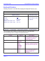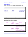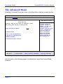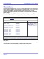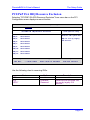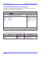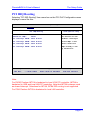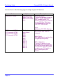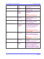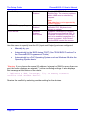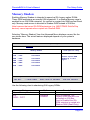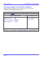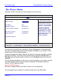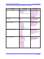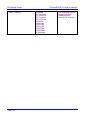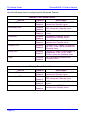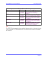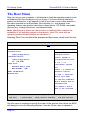
1
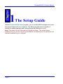
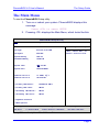
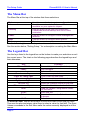
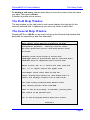
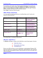
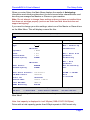
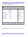
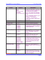
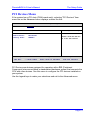
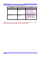
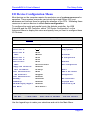
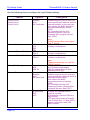
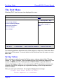
PhoenixBIOS 4.0 User's Manual for Pentium based MSC Boards Version 2.1 Copying of this document, and giving it to others and the use or communication of the contents therof, are forbidden without express authority. Offenders are liable to the payment of damages. All rights are reserved in the event of the grant of a patent or the registration of a utility model or design. Weitergabe sowie Vervielfältigung dieser Unterlage, Verwertung und Mitteilung ihres Inhalts nicht gestattet, soweit nicht ausdrücklich zugestanden. Zuwiderhandlungen verpflichten zu Schadenersatz. Alle Rechte für den Fall einer Patenterteilung oder GebrauchsmusterEintragung vorbehalten. Page i Contents PhoenixBIOS 4.0 User's Manual The information contained in this users manual is subject to change without previous notice. The programs are provided "as is" without warranty of any kind either expressed or implied, including but not limited to the implied warranties of merchantability and fitness for a particular purpose. This publication could contain technical inaccuracies or typographical errors. Furthermore, MSC and Phoenix Technologies will not be held liable for errors in this users manual as well as coincidental or sequential damages in connection with the delivery, performance and use of this material. MS-DOS, Windows and Microsoft are registered trademarks of the Microsoft Corporation. PS/2 and IBM are trademarks of the International Business Machines Corporation. Copyright 2001, Phoenix Technologies Ltd. Copyright 2001, MSC Vertriebs GmbH Zeppelinstraße 1a 85375 Neufahrn Germany Purpose of Document This guide explains how to configure your PC and optimize its performance using the Setup program. It also explains how to use the BIOS function calls in writing computer programs. Page ii PhoenixBIOS 4.0 User's Manual Contents Contents ABOUT THIS MANUAL ....................................................................................1 CHAPTER 1 - THE SETUP GUIDE....................................................................2 THE MAIN MENU ..............................................................................................3 The Menu Bar............................................................................................4 The Legend Bar .........................................................................................4 The Field Help Window ..............................................................................5 The General Help Window .........................................................................5 Main Menu Selections ................................................................................6 Masters and Slaves....................................................................................6 Keyboard Features ..................................................................................10 POST Options..........................................................................................11 THE ADVANCED MENU ....................................................................................12 Memory Cache ........................................................................................14 PCI / PnP Configuration ...........................................................................16 PCI/PnP ISA UMB Region Exclusion ........................................................18 PCI/PnP ISA IRQ Resource Exclusion ......................................................19 PCI/PnP ISA DMA Resource Exclusion.....................................................20 PCI IRQ Routing ......................................................................................21 PCI Devices Menu ...................................................................................23 I/O Device Configuration Menu.................................................................25 Memory Shadow ......................................................................................29 Advanced Chipset Control (PISA Pentium)................................................30 Advanced Chipset Control (EURO Pentium) ............................................32 THE SECURITY MENU ......................................................................................33 THE POWER MENU .........................................................................................36 Advanced Options....................................................................................39 THE BOOT MENU............................................................................................42 THE EXIT MENU .............................................................................................44 Page iii Contents PhoenixBIOS 4.0 User's Manual Saving Values ......................................................................................... 44 Exit Discarding Changes.......................................................................... 45 Load Setup Defaults ................................................................................ 45 Discard Changes..................................................................................... 45 Save Changes......................................................................................... 45 PHOENIXBIOS MESSAGES .............................................................................. 46 CHAPTER 2 - BOOT UTILITIES ..................................................................... 51 PHOENIX QUIET BOOT ..................................................................................... 51 Press <ESC> .......................................................................................... 51 Press <F2> ............................................................................................. 52 POST Error ............................................................................................. 52 Keyboard Input Request .......................................................................... 52 PHOENIX MULTIBOOT ..................................................................................... 53 The Setup Boot Menu.............................................................................. 53 The Boot First Menu ................................................................................ 54 Boot with Blanked Video .......................................................................... 54 CHAPTER 3 - PHOENIX PHLASH.................................................................. 57 INSTALLATION ................................................................................................ 57 CREATE THE CRISIS RECOVERY DISKETTE ......................................................... 58 UPDATING THE CRISIS RECOVERY DISKETTE ...................................................... 58 EXECUTING PHOENIX PHLASH .......................................................................... 58 CRISIS RECOVERY MODE ................................................................................ 60 INDEX ............................................................................................................ 61 Page iv A bout This Manual This manual is divided into the following chapters: Chapter 1 - The Setup Guide This chapter describes a typical menu-driven Phoenix Setup program, which allows you to specify changes in the computer hardware (e.g. add a new diskette drive) and optimize system performance. Setup maximizes your control over your system's features and performance. This Setup Guide is only an example. The Setup menus on your computer may be quite different. Consult the Setup manual supplied with your computer. Chapter 2 - PhoenixBIOS Utilities This chapter describes two new programs that give you more control over the boot process: + Phoenix QuietBoot + Phoenix MultiBoot Chapter 3 - Phoenix Phlash This chapter describes how to use the Phoenix Phlash utility for upgrading your BIOS without having to replace the BIOS ROM chip. Page 1 PhoenixBIOS 4.0 User's Manual 1 The Setup Guide With the PhoenixBIOS Setup program, you can modify BIOS settings and control the special features of your computer. The Setup program uses a number of menus for making changes and turning the special features on or off. Note: The menus shown here are from a typical system. The actual menus displayed on your screen may be quite different and depend on the hardware and features installed in your computer. Page 2 PhoenixBIOS 4.0 User's Manual The Setup Guide The Main Menu To start the PhoenixBIOS Setup utility: 1. Turn on or reboot your system. PhoenixBIOS displays this message: Press <F2> to enter SETUP 2. Pressing <F2> displays the Main Menu, which looks like this: PhoenixBIOS Setup Utility Main Advanced Security Power Boot Exit Item Specific Help CPU Type Pentium with MMX <Tab>, <Shift-Tab>, or CPU Speed 266 MHz <Enter> selects field. System Memory 640 kB Extemded Memory 15360 kB System Time: [16:19:20] System Date: [05/04/2000] Diskette Drive A: [1.44MB, 3«"] Diskette Drive B: [Disabled] P Primary IDE Master: [ST34321A-(PM)] P Primary IDE Slave: [None] P Secondary IDE Master: [None] P Secondary IDE Slave: [None] P Keyboard Features P POST Options F1 Help XY Select Item -/+ Change Values ESC Exit [Z Select Menu Enter Select P Sub-Menu F9 Setup Defaults F10 Save and Exit See p. 7 for a description of the fields on this menu. Page 3 The Setup Guide PhoenixBIOS 4.0 User's Manual The Menu Bar The Menu Bar at the top of the window lists these selections: Main Advanced Use this menu for basic system configuration. Use this menu to set the Advanced Features available on your system's chipset. Security Use this menu to set User and Supervisor Passwords and the Backup and Virus-Check reminders. Power Use this menu to configure Power-Management features. Boot Use this menu to configure Boot options. Exit Exits the current menu. Use the left and right Ö arrow keys to make a selection. See the section below, "Exiting Setup," for a description on exiting the Main Menu. The Legend Bar Use the keys listed in the legend bar on the bottom to make your selections or exit the current menu. The chart on the following page describes the legend keys and their alternates: Key <F1> or <Alt-H> <Esc> Ö arrow keys ↑ or ↓ arrow keys <Tab> or <Shift-Tab> <Home> or <End> <PgUp> or <PgDn> <F5> or <-> <F6> or <+> or <Space> <F9> Function General Help window (See below). Exit this menu. Select a different menu. Move cursor up and down. Cycle cursor up and down. Move cursor to top or bottom of window. Move cursor to next or previous page. Select the Previous Value for the field. Select the Next Value for the field. Load the Default Configuration values for this menu. <F10> Save and exit. <Enter> Execute Command or Select P Submenu. <Alt-R> Refresh screen. To select an item, use the arrow keys to move the cursor to the field you want. Then use the plus-and-minus value keys to select a value for that field. The Save Values commands in the Exit Menu save the values currently displayed in all the menus. Page 4 PhoenixBIOS 4.0 User's Manual The Setup Guide To display a sub menu, use the arrow keys to move the cursor to the sub menu you want. Then press <Enter>. A pointer (P) marks all sub menus. The Field Help Window The help window on the right side of each menu displays the help text for the currently selected field. It updates as you move the cursor to each field. The General Help Window Pressing <F1> or <Alt-H> on any menu brings up the General Help window that describes the legend keys and their alternates: General Help Setup changes system behavior by modifying the BIOS configuration parameters. Selecting incorrect values may cause system boot failure; load Setup Default values to recover. <Up/Down> arrows select fields in current menu. <PgUp/PgDn> moves to previous/next page on scrollable menus. <Home/End> moves to top/bottom item of current menu. Within a field, <F5> or <-> selects next lower value and <F6>, <+>, or <Space> selects next higher value. <Left/Right> arrows select menus on menu bar. <Enter> displays more options for items marked with a P. <Enter> also displays an option list on some fields. <F9> loads factory-installed Setup Default values. <F10> restores previous values from CMOS. <ESC> or <Alt-X> exits Setup; in sub-menus, pressing these keys returns to the previous menu. <F1> or <Alt-H> displays General Help (this screen). [Continue] Page 5 The Setup Guide PhoenixBIOS 4.0 User's Manual The scroll bar on the right of any window indicates that there is more than one page of information in the window. Use <PgUp> and <PgDn> to display all the pages. Pressing <Home> and <End> displays the first and last page. Pressing <Enter> displays each page and then exits the window. Press <Esc> to exit the current window. Main Menu Selections You can make the following selections on the Main Menu itself. Use the sub menus for other selections. Feature Options CPU Type N/A CPU Speed N/A System Memory N/A Extended Memory N/A System Time System Date Diskette Drive A Diskette Drive B HH:MM:SS MM/DD/YYYY Disabled 1.44 MB, 3 ½" 2.88 MB, 3 ½" Description Displays type of processor detected during bootup. Displays the clock rate detected during bootup. Displays amount of conventional memory detected during bootup. Displays the amount of extended memory detected during bootup. Set the system time. Set the system date. Select the type of floppy-disk drive installed in your system. You can set the boot sequence of the bootable drives by selecting Boot Sequence on the Main Menu or opening the Boot Menu. Masters and Slaves The Master and Slave settings on the Main Menu control these types of devices: + Hard-disk drives + Removable-disk drives + CD-ROM drives There is one IDE connector on your motherboard, usually labelled "Primary IDE". There are usually two connectors on each ribbon cable attached to IDE connector. When you have connected two drives to this connector, the one on the end of the cable is the Master. Page 6 PhoenixBIOS 4.0 User's Manual The Setup Guide When you enter Setup, the Main Menu displays the results of Autotyping– information each drive provides about its own size and other characteristics–and how they are arranged as Masters or Slaves on your machine. Note: Do not attempt to change these settings unless you have an installed drive that does not autotype properly (such as an older hard-disk drive that does not support autotyping). If you need to change your drive settings, select one of the Master or Slave drives on the Main Menu. This will display a menu like this: PhoenixBIOS Setup Utility Main Primary IDE Master [ST34321A-(PM)] Type: Item Specific Help [Auto] None = disables any CHS Format attached drive Cylinders: [ 8894] Heads: [ 15] Auto = detect drive Sectors/Track: [ 63] Maximum Capacity: 4104MB parameters automatically User = drive parameters LBA Format Total Sectors: 8404830 Maximum Capacity: 4104MB must be entered by user Multi-Sector Transfers: [16 Sectors] LBA Mode Control: [Enabled] 32-bit I/O: [Disabled] Transfer Mode: [FPIO 4 / DMA 2] Ultra DMA Mode: [Mode 2] SMART Monitoring: Enabled F1 CD-ROM = a CD-ROM drive is installed Help XY Select Item -/+ ESC Exit [Z Select Menu Enter Select P Sub-Menu Change Values F9 Setup Defaults F10 Save and Exit Use the legend keys listed on the bottom to make your selections and exit to the Main Menu. Note: that capacity is displayed in ‘real’ Mbytes (1MB=1024*1024 Bytes) Drives with a total capacity greater than 8Gbyte operate in LBA format only. Page 7 The Setup Guide PhoenixBIOS 4.0 User's Manual The CHS parameters are not displayed by the fixed disk menu. In this case the menu is shown like this: PhoenixBIOS Setup Utility Main Primary IDE Master [IBM-DPTA-372050-(PM)] Type: [Auto] Item Specific Help None = disables any attached drive LBA Format Total Sectors: 40088160 Auto = detect drive Maximum Capacity: 19574MB parameters automatically Multi-Sector Transfers: [16 Sectors] User = drive parameters LBA Mode Control: [Enabled] 32-bit I/O: [Disabled] Transfer Mode: [FPIO 4 / DMA 2] Ultra DMA Mode: [Mode 2] SMART Monitoring: Enabled must be entered by user CD-ROM = a CD-ROM drive is installed F1 Help XY Select Item -/+ ESC Exit [Z Select Menu Enter Select P Sub-Menu Change Values F9 Setup Defaults F10 Save and Exit Use the chart on the following page to configure the hard disk drive with Advanced Hard Disk Features: Page 8 PhoenixBIOS 4.0 User's Manual Feature Type Cylinders Heads Sectors/Track Multi-Sector Transfers LBA Mode Control Options None User Auto IDE Removable CD-ROM ATAPI Removable 1 to 65,536 1 to 16 1 to 63 Disabled Standard 2 sectors 4 sectors 8 sectors 16 sectors Enabled Disabled 32-Bit I/O Enabled Disabled Transfer Mode Standard Fast PIO 1 Fast PIO 2 Fast PIO 3 Fast PIO 4 FPIO 3 / DMA 1 FPIO 4 / DMA 2 Disabled Mode 0 Mode 1 Mode 2 Mode 3 Mode 4 Enabled Disabled Ultra DMA Mode SMART Monitoring The Setup Guide Description None = Autotyping is not able to supply the drive type or end user has selected None, disabling any drive that may be installed. User = You supply the hard-disk drive information in the following fields. Auto = Autotyping, the drive itself supplies the information. CD-ROM = CD-ROM drive. ATAPI Removable = Removable disk drive. Number of cylinders. Number of read/write heads. Number of sectors per track. Any selection except Disabled determines the number of sectors transferred per block. Standard is 1 sector per block. Enabling LBA causes Logical Block Addressing to be used in place of Cylinders, Heads, & Sectors. Enables 32-bit communication between CPU and IDE card. Requires PCI or local bus. Selects the method for transferring the data between the hard disk and system memory. The Setup menu only lists those options supported by the drive and platform. Ultra DMA Mode supports 33 MB/sec transfer rate for fixed disk drives. ‘Enabled’ installs Self-Monitoring Analysis-Reporting Technology, which issues a warning if an IDE failure is imminent. WARNING: Incorrect settings can cause your system to malfunction. Page 9 The Setup Guide PhoenixBIOS 4.0 User's Manual Keyboard Features Selecting "Numlock" on the Main Menu displays the Keyboard Features menu: PhoenixBIOS Setup Utility Main Keyboard Features Item Specific Help Numlock: [Off] Selects Power-on state Key Click: [Disabled] for Numlock. Keyboard auto-repeat rate: [30/sec] Keyboard auto-repeat delay: [1/2 sec] F1 Help XY Select Item -/+ Change Values ESC Exit [Z Select Menu Enter Select P Sub-Menu F9 Setup Defaults F10 Save and Exit Use the legend keys to make your selections and exit to the Main Menu. Use the following chart to configure the keyboard features: Feature Numlock Key Click Keyboard auto-repeat rate Keyboard auto-repeat delay Page 10 Options Auto On Off Enabled Disabled 2/sec 6/sec 10/sec 13.3/sec 21.8/sec 26.7/sec 30/sec ¼ sec ½ sec ¾ sec 1 sec Description On or Off turns NumLock on or off at bootup. Auto turns NumLock on if it finds a numeric key pad. Turns audible key click on. Sets the number of times a second to repeat a keystroke when you hold the key down. Sets the delay time after the key is held down before it begins to repeat the keystroke. PhoenixBIOS 4.0 User's Manual The Setup Guide POST Options Selecting "POST Options" on the Main Menu displays the following menu. PhoenixBIOS Setup Utility Main POST Options Item Specific Help QuietBoot Mode: [Disabled] Display the diagnostic QuickBoot Mode: [Enabled] screen during boot Summary screen: [Enabled] Boot with keyboard: [Enabled] F1 Help XY Select Item -/+ Change Values ESC Exit [Z Select Menu Enter Select P Sub-Menu F9 Setup Defaults F10 Save and Exit Use the legend keys to make your selections and exit to the Main Menu. Use the following chart to select your boot options. Feature QuietBoot Mode Options Enabled Disabled QuickBoot Mode Enabled Disabled Summary screen Enabled Disabled Enabled Disabled Boot with keyboard Description Suppress the diagnostic screen during boot. Optionally a customer-specific graphic illustration can be displayed. Allows the system to skip certain tests while booting. This will decrease the time needed to boot the system. Displays system summary screen during bootup. Allow system bootup without an attached keyboard. POST will not report keyboard errors if this option is set to Enabled Page 11 The Setup Guide PhoenixBIOS 4.0 User's Manual The Advanced Menu Selecting "Advanced" from menu bar on the Main Menu displays a menu like this: PhoenixBIOS Setup Utility Main Advanced Security Power Boot Exit Item Specific Help Setup Warning Setting items on this menu to incorrect values may cause your system to malfunction. Large Disk Access Mode: [DOS] P Memory Cache P PCI / PnP Configuration P I/O Device Configuration P Memory Shadow UNIX, Novell NetWare, or other operating systems, select 'Other', If you are installing new software and the drive fails, change this selection and try again. Different operating systems require different representations of drive geometries. P Advanced Chipset Control F1 Help XY Select Item -/+ Change Values ESC Exit [Z Select Menu Enter Select P Sub-Menu F9 Setup Defaults F10 Save and Exit Use the legend keys to make your selections and exit to the Main Menu. Use the chart on the following page to configure the Large Disk Access Mode Features: Page 12 PhoenixBIOS 4.0 User's Manual Feature Large Disk Access Mode The Setup Guide Options Description DOS Other Select ‘DOS’ if you have DOS. Select ‘Other’ if you have UNIX, Novell NetWare or other operating systems. If you are installing new operating system software and the drive fails, change this setting and try again. A large disk is one that has more than 1024 cylinders, more than 16 heads, or more than 63 tracks per sector. Warning: Incorrect settings can cause your system to malfunction. Page 13 The Setup Guide PhoenixBIOS 4.0 User's Manual Memory Cache Enabling cache saves time for the CPU by holding data most recently accessed in regular memory (dynamic RAM or DRAM) in a special storage area of static RAM (SRAM), which is faster. Before accessing regular memory, the CPU first accesses the cache. If it does not find the data it is looking for there, it accesses regular memory. Selecting "Memory Cache" from the Advanced Menu displays a menu like the one shown here. The actual features displayed depend on your system's hardware. PhoenixBIOS Setup Utility Advanced Memory Cache Memory Cache: [Enabled] Cache System BIOS area: [Enabled] Cache Video BIOS area: [Enabled] Cache CC00 - CFFF: [Disabled] Cache D000 - D3FF: [Disabled] Cache D400 - D7FF: [Disabled] Cache D800 - DBFF: [Disabled] Cache DC00 - DFFF: [Disabled] F1 Item Specific Help Sets the state of the memory cache. Second Level (L2) Cache is Enabled / Disabled. Help XY Select Item -/+ ESC Exit [Z Select Menu Enter Select P Sub-Menu Change Values F9 Setup Defaults F10 Save and Exit Use the legend keys listed on the bottom to make your selections and exit to the Main Menu. Use the chart on the following page to configure the memory cache. Page 14 PhoenixBIOS 4.0 User's Manual Feature Memory Cache Cache System BIOS area Options Enabled Disabled. Enabled Disabled Cache Video BIOS area Enabled Disabled Cache segments, e.g., D000-D3FF Enabled Disabled The Setup Guide Description Generally enables or disables all memory caching (default enabled) Caches the system BIOS and improves performance (default enabled). Caches the video BIOS and improves performance (default enabled). Controls caching of individual segments of memory usually reserved for shadowing system or option ROMs (default disabled). WARNING: Incorrect settings can cause your system to malfunction. NOTE: The contents of this menu depend on the chipset installed on your motherboard, and chipsets vary widely. Consult your dealer or the computer manual before changing the items on this menu. Incorrect settings can cause your system to malfunction. Page 15 The Setup Guide PhoenixBIOS 4.0 User's Manual PCI / PnP Configuration Selecting "PCI / PnP Configuration" from menu bar on the Advanced menu displays a menu like this: PhoenixBIOS Setup Utility Advanced PCI / PnP Configuration Plug & Play O/S: [No] ISA graphics device installed: [No] Default Primary Video Adapter: [AGP] Item Specific Help Select 'Yes' if you are using a Plug & Play capable operating system. Select 'No' if you need the BIOS to configure non_boot devices. P PCI/PNP ISA UMB Region Exclusion P PCI/PNP ISA IRQ Resource Exclusion P PCI/PNP ISA DMA Resource Exclusion P PCI IRQ Routing P PCI Device, Slot #1 P PCI Device, Slot #2 P PCI Device, Slot #3 P PCI Device, Slot #4 Reset Configuration Data: [No] Secured Setup Configurations: [No] Help XY Select Item -/+ ESC Exit F1 [Z Select Menu Enter Select P Sub-Menu Change Values F9 Setup Defaults F10 Save and Exit PCI Devices are devices equipped for operation with a PCI (Peripheral Component Interconnect) bus, a standardized hardware system that connects the CPU with other devices. Use this menu to configure the PCI devices installed on your system and to reserve system resources for non-PnP ISA devices. Use the legend keys to make your selections and exit to the Advanced menu. Page 16 PhoenixBIOS 4.0 User's Manual The Setup Guide The following table illustrates the possible selections: Feature Plug & Play O/S Options Yes No ISA graphics device installed Yes No Default Primary Video Adapter PCI AGP Yes No Reset Configuration Data Secured Setup Configurations Yes No Description Select ‘Yes’ if you are using a Plug & Play capable operating system. Select ‘No’ if you need the BIOS to configure non.boot devices. Enable ISA (non-VGA) graphics device to access pallete data in PCI VGA device. Select Bootdisplay on either PCI VGA card or AGP VGA. ‘Yes’ erases all configuration data in ESCD, which stores the configuration settings for non-PnP plug-in devices. Select ‘Yes’ when required to restore the manufacturer's defaults. ‘Yes’ prevents a PnP operating system from overriding selections you have made in Setup. Note: Selections for PCI Device Slot #1 - #4 are not supported by EURO Pentium Page 17 The Setup Guide PhoenixBIOS 4.0 User's Manual PCI/PnP ISA UMB Region Exclusion Selecting "PCI/PNP ISA UMB Region Exclusion" from menu bar on the PCI Configuration menu displays a menu like this: PhoenixBIOS Setup Utility Advanced PCI/PNP ISA UMB Region Exclusion CC00 - CFFF: [Available] D000 - D3FF: [Available] D400 - D7FF: [Available] D800 - DBFF: [Available] DC00 - DFFF: [Available] F1 Item Specific Help Reserves the specified block of upper memory for use by legacy ISA devices. Help XY Select Item -/+ Change Values ESC Exit [Z Select Menu Enter Select P Sub-Menu F9 Setup Defaults F10 Save and Exit Use the following chart in reserving upper memory: Feature Upper Memory Block: e.g. D400 – D7FF Page 18 Options Available Reserved Description Reserves the specified block of upper memory for use by legacy ISA devices. PhoenixBIOS 4.0 User's Manual The Setup Guide PCI/PnP ISA IRQ Resource Exclusion Selecting "PCI/PNP ISA IRQ Resource Exclusion" from menu bar on the PCI Configuration menu displays a menu like this: PhoenixBIOS Setup Utility Advanced PCI/PNP ISA IRQ Resource Exclusion Item Specific Help IRQ 3: [Available] Reserves the specified IRQ 4: [Available] IRQ for use by legacy IRQ 5: [Available] ISA devices. IRQ 7: [Available] IRQ 9: [Available] IRQ 10: [Available] IRQ 11: [Available] IRQ 12: [Available] Help XY Select Item -/+ ESC Exit F1 [Z Select Menu Enter Select P Sub-Menu Change Values F9 Setup Defaults F10 Save and Exit Use the following chart in reserving IRQs: Feature IRQ: e.g. IRQ 7 Options Available Reserved Description Reserves the specified IRQ for use by legacy ISA devices. Page 19 The Setup Guide PhoenixBIOS 4.0 User's Manual PCI/PnP ISA DMA Resource Exclusion Selecting "PCI/PNP DMA IRQ Resource Exclusion" from menu bar on the PCI Configuration menu displays a menu like this: PhoenixBIOS Setup Utility Advanced PCI/PNP ISA DMA Resource Exclusion Item Specific Help DMA 1: [Available] Reserves the specified DMA 3: [Available] DMA channel DMA 5: [Available] Non-Plug-and-Play ISA devices. Help XY Select Item -/+ ESC Exit F1 [Z Select Menu Enter Select P Sub-Menu Change Values F9 for use by Setup Defaults F10 Save and Exit Use the following chart in reserving ISA DMA channels: Feature DMA: e.g. DMA 1 Page 20 Options Available Reserved Description Reserves DMA channel 1 for legacy ISA device. PhoenixBIOS 4.0 User's Manual The Setup Guide PCI IRQ Routing Selecting "PCI IRQ Routing" from menu bar on the PCI /PnP Configuration menu displays a menu like this: PhoenixBIOS Setup Utility Advanced PCI IRQ Routing Shared PCI IRQs: Item Specific Help [Auto] PCI devices can use PCI Interrupt INTA#: [Auto Select] hardware interrupts PCI Interrupt INTB#: [Auto Select] called IRQs. A PCI PCI Interrupt INTC#: [Auto Select] device cannot use PCI Interrupt INTD#: [Auto Select] IRQs already in use by ISA devices Help XY Select Item -/+ ESC Exit F1 [Z Select Menu Enter Select P Sub-Menu Change Values F9 Setup Defaults F10 Save and Exit Note: For EURO Pentium INTC# is hardwired to local VGA PCI controller, INTD# is hardwired to USB and local LAN PCI controller. Note that INTD# is always used as shared interrupt. Selections for INTA#, INTB# IRQ routing is not supported For PISA Pentium INTC# is hardwired to local LAN controller. Page 21 The Setup Guide PhoenixBIOS 4.0 User's Manual Use the chart on the following page in configuring the PCI devices: Feature Shared PCI IRQs PCI Interrupt INTA# PCI Interrupt INTB# PCI Interrupt INTC# PCI Interrupt INTD# Page 22 Options Share One IRQ Share Two IRQs Share Three IRQs Auto Disabled Auto Select IRQ 3 IRQ 4 IRQ 5 IRQ 7 IRQ 9 IRQ 10 IRQ 11 IRQ 12 IRQ 14 IRQ 15 Description Share ‘n’ IRQ’s: Forces PCI devices to use at most ‘n’ IRQs. ‘Share One IRQ’ means that all PCI devices in system are shared to one IRQ line. This frees up remaining IRQ lines for non-PnP ISA devices. Auto: Minimizes PCI IRQ Sharing Disabled : Do not use IRQ with PCI interrupt. Auto Select: IRQ assigment is selected by Plug&Play with priority. IRQ n Selection: Forces PCI device to use selected IRQ. This selection is used for drivers which rely on a specific IRQ. Be careful to choose an IRQ which is NOT used by any ISA device. PhoenixBIOS 4.0 User's Manual The Setup Guide PCI Devices Menu If the system has a PCI slots (PISA boards only), selecting "PCI Devices" from menu bar on the Advanced menu displays a menu like this: PhoenixBIOS Setup Utility Advanced PCI Device, Slot #1 Enable Master: [Disabled] Latency Timer: [0040h] F1 Item Specific Help Enable selected device As a PCI bus master Help XY Select Item -/+ Change Values ESC Exit [Z Select Menu Enter Select P Sub-Menu F9 Setup Defaults F10 Save and Exit PCI Devices are devices equipped for operation with a PCI (Peripheral Component Interconnect) bus, a standardized hardware system that connects the CPU with other devices. Use this menu to configure the PCI devices installed on your system. Use the legend keys to make your selections and exit to the Advanced menu. Page 23 The Setup Guide PhoenixBIOS 4.0 User's Manual Use the following chart in configuring the PCI devices: Feature PCI Device Slots 1-n: Enable Master Latency Timer Options Disabled Enabled 0000h to 0280h Description Enables selected device as a PCI bus master. Not every device can function as a master. Check your device documentation. Bus master clock rate. A high-priority, highthroughput device may benefit from a greater value. NOTE: The contents of this menu depend on the devices installed on your system. Incorrect settings can cause your system to malfunction. Page 24 PhoenixBIOS 4.0 User's Manual The Setup Guide I/O Device Configuration Menu Most devices on the computer require the exclusive use of system resources for operation. These system resources can include Input and Output (I/O) port addresses and Interrupt lines for getting the attention of the CPU. Allocating these resources to various devices is called device configuration. To configure the serial and parallel ports, the diskette controller, the USB Controller and the IDE Controller, select "I/O Device Configuration" on the Advanced Menu to display this menu and specify how you want to configure these I/O Devices: PhoenixBIOS Setup Utility Advanced I/O Device Configuration Item Specific Help Configure serial port A Serial Port A: [Auto] Serial Port B: [Auto] Mode: using options: [Normal] [Disabled] Serial Port C: [Auto] No configuration Serial Port D: [Auto] Parallel Port: [Auto] [Enabled] [Bi-directional] User configuration Mode: Floppy Disk Controller [Enabled] Base I/O address: [Primary] [Auto] [Both] BIOS or OS chooses [Swapped] configuration Local IDE Controller: IDE Connectors: Local LAN Controller: [Enabled] Watchdog: [Disabled] [OS Controlled] DiskOnChip: [Enabled] Displayed when USB BIOS Legacy Support: [Enabled] controlled by OS PS/2 Mouse: [Auto Detect] F1 Help XY Select Item -/+ Change Values ESC Exit [Z Select Menu Enter Select P Sub-Menu F9 Setup Defaults F10 Save and Exit Use the legend keys to make your selections and exit to the Main Menu. Page 25 The Setup Guide PhoenixBIOS 4.0 User's Manual Use the following chart to configure the Input/Output settings: Feature Serial Serial Serial Serial Port Port Port Port A: B: C: D: Base I/O Address Interrupt (Port A, Port B) Interrupt (Port C Port D) Options Disabled Enabled Auto OS Controlled 3F8 2F8 3E8 2E8 IRQ 4 IRQ 3 IRQ 10 IRQ 11 Mode (Port B only) Normal IrDA ASK-IR Parallel Port: Disabled Enabled Auto OS Controlled Mode Page 26 Output only Bi-directional EPP ECP Description Disabled turns off the port. Enabled requires you to enter the base Input/Output address and the Interrupt number on the next line. Auto makes the BIOS configure the port automatically during POST. OS Controlled lets the PnP Operating System (such as Windows 98) configure the port after POST. Note: EURO Pentium does not support Port C, Port D If you select Enabled, choose one of these combinations. If you select Enabled, choose one of these combinations. If you select Enabled, choose one of these combinations. Note: These interrupts are not used by EURO Pentium If the port is not disabled, choose one of these combinations. ASK-IR means Sharp IR with Amplitude Shift Key Disabled turns off the port. Enabled requires you to enter the base Input/Output address and the Interrupt number below. Auto makes the BIOS autoconfigure the port during POST. OS Controlled lets the PnP Operating System (Windows 9x) configure the port after POST. Output only is standard one-way protocol for a parallel device, typically a printer. Bi-directional uses the PS/2 twoway protocol EPP specifies Enhanced Parallel Port Protocol Rev. 1.9 and ECP is used in conjunction with 8-Bit DMA transfer.. PhoenixBIOS 4.0 User's Manual Base I/O Address Interrupts DMA channel Floppy Disk Controller 378 278 3BC IRQ5 IRQ7 DMA 0 DMA 1 DMA 2 DMA 3 Disabled Enabled Base I/O Address Primary Secondary Local IDE Controller Disabled Primary Secondary Both IDE Connectors Standard Swapped Local LAN Controller Disabled Enabled Watchdog Disabled 250h 270h The Setup Guide If you select Enabled for the Parallel Port, choose one of these I/O addresses. If you select Enabled for the Parallel Port, choose one of these interrupt options. If you select ECP for the Parallel Port Mode, choose one of these DMA options. Note: DMA channel 0 and 2 are not supported by EURO Pentium. Enables the on-board legacy diskette controller. Disabled turns off all legacy diskette drives. If you select Enabled for the Diskette Controller. Always choose Primary if no external controller is installed . Enables the on-board IDE controller. Primary IDE channel is at i/o address 1F0h and IRQ 14, Secondary IDE channel is at i/o address 170h and IRQ 15. Note: EURO Pentium only supports Primary IDE. Selections only offer ‘Enable’, ‘Disable’ This selection chooses between a 40-Pin (2.54mm) and a 44-Pin (2.0mm) connector assigned to either Primary or Secondary IDE. Note: This selection is not supported by EURO Pentium Enables the on-board LAN controller. If Disabled, the LAN controller is not present on the PCI bus. Enables the on-board Watchdog controller at the selected Base I/O address. The Watchdog device is started and retriggered by i/o access to this address. For more information on this device please refer to the hardware user manual. Page 27 The Setup Guide DiskOnChip PhoenixBIOS 4.0 User's Manual Disabled Enabled USB BIOS Legacy Support Disabled Enabled PS/2 Mouse Disabled Enabled Auto Detect Enable MSYSTEMS Flash disk DiskOnChip. The memory address within UMB area is selected by jumpers. Note: This selection is not supported by EURO Pentium Legacy USB Support emulates a standard PS/2 Keyboard and Mouse to system. ‘Disabled’ disables any installed PS/2 mouse and frees up IRQ 12. ‘Enabled’ forces the PS/2 mouse port to be enabled regardless if a mouse is present. ‘Auto Detect’ lets the BIOS control the mouse. Use this menu to specify how the I/O (Input and Output) ports are configured: • Manually by you. • Automatically by the BIOS during POST (See "ROM BIOS Functions" in the PhoenixBIOS Programmer’s Guide) • Automatically by a PnP Operating System such as Windows 98 after the Operating System boots. Warning: If you choose the same I/O address, Interrupt or DMA for more than one port, the menu displays an asterisk (*) at the conflicting settings. It also displays this message at the bottom of the menu: * Indicates a DMA, Interrupt, I/O, or memory resource conflict with another device. Resolve the conflict by selecting another setting for the devices. Page 28 PhoenixBIOS 4.0 User's Manual The Setup Guide Memory Shadow Enabling Memory Shadow is intended to speed up ISA Legacy option ROMs. These ROM extensions are usually 8-Bit organized. If a shadow Memory area is enabled for an ISA ROM extension, it’s content is copyied into RAM and set Read only. Memory read access is directed to Shadow RAM instead of ISA Bus. Note however that some ISA ROM extensions (e.g. MSYSTEMS DiskOnChip devices) cannot operate when copied into Shadow RAM. Selecting "Memory Shadow" from the Advanced Menu displays a menu like the one shown here. The actual features displayed depend on your system's hardware. PhoenixBIOS Setup Utility Advanced Memory Shadow CC00 - CFFF: [Disabled] D000 - D3FF: [Disabled] D400 - D7FF: [Disabled] D800 - DBFF: [Disabled] DC00 - DFFF: [Disabled] F1 Item Specific Help Enables option ROM shadowing in this region. Help XY Select Item -/+ ESC Exit [Z Select Menu Enter Select P Sub-Menu Change Values F9 Setup Defaults F10 Save and Exit Use the following chart in shadowing ISA Legacy ROMs: Feature Upper Memory Block: e.g. D400 – D7FF Options Disabled Enabled Description If set to Disabled, ISA Legacy ROM extension are accessed on ISA Bus. If set to Enabled the ISA ROM extesion is copied into Shadow RAM (Read Only). Page 29 The Setup Guide PhoenixBIOS 4.0 User's Manual Advanced Chipset Control (PISA Pentium) Selecting "Advanced Chipset Control" from menu bar on the PCI /PnP Configuration menu displays a menu like this: PhoenixBIOS Setup Utility Advanced Advanced Chipset Control Item Specific Help SDRAM CAS Latency [3T] Select SDRAM RAS to CAS ISA I/O recovery time: [2 BUSCLK] Latency Timing. AT bus clock frequency: [PCICLK/4] Graphics Aperture: F1 [ 64MB] Help XY Select Item -/+ ESC Exit [Z Select Menu Enter Select P Sub-Menu Page 30 Change Values F9 Setup Defaults F10 Save and Exit PhoenixBIOS 4.0 User's Manual The Setup Guide Use the following chart in configuring the Advanced Chipset Control: Feature SDRAM CAS Latency ISA I/O Recovery Time AT bus clock frequency Graphics Aperture Options 3T 2T Disabled 2 BUSCLK 4 BUSCLK 8 BUSCLK 14 BUSCLK 7.159MHz PCICLK/4 4 MB 8 MB 16 MB 32 MB 64 MB 128 MB 256 MB Description Select the RAS to CAS timing of installed SDRAM. Inspect SDRAM RAS to CAS specification first before setting a value of 2T. Setting 2T value for SDRAM specified for 3T will cause system to hang or malfunction. Number of ISA clocks recovery time for 8-bit or 16bit I/O. The recommended value is 2 BUSCLK. Select AT bus clock frequency either with fixed 7.159MHz or derived from PCI clock. The PCI clock is normally 33MHz. Select the size of mapped memory for AGP graphic data. NOTE: The contents of this menu depend on the devices installed on your system. Incorrect settings can cause your system to malfunction. Page 31 The Setup Guide PhoenixBIOS 4.0 User's Manual Advanced Chipset Control (EURO Pentium) PhoenixBIOS Setup Utility Advanced Advanced Chipset Control Item Specific Help ISA clock cycles 8-bit I/O Recovery: [4.5] inserted between 16-bit I/O Recovery: [4.5] back-to-back I/O. F1 Help XY Select Item -/+ Change Values ESC Exit [Z Select Menu Enter Select P Sub-Menu F9 Setup Defaults F10 Save and Exit Use the following chart in configuring the Advanced Chipset Control: Feature 8-bit I/O Recovery Options 3.5, 11.5, 4.5, 5.5, 6.5, 7.5, 8.5, 9.5, 10.5 16-bit I/O Recovery 3.5, 7.5, 4.5, 5.5, 6.5 Page 32 Description Number of ISA clocks recovery time for 8-bit I/O. The minimum I/O delay is 3.5 Sysclocks Number of ISA clocks recovery time for 16-bit I/O. The minimum I/O delay is 3.5 Sysclocks PhoenixBIOS 4.0 User's Manual The Setup Guide The Security Menu Selecting "Security" from the Main Menu displays a menu like this: PhoenixBIOS Setup Utility Main Advanced Security Power Boot Exit Item Specific Help Supervisor Password Is: Set User Password Is: Clear Set Supervisor Password [Enter] Set User Password [Enter] Network Server Mode: [Disabled] Password on boot: [Disabled] Fixed disk boot sector: [Normal] Diskette access: [Supervisor] Virus check reminder: [Disabled] System backup reminder: [Disabled] F1 Supervisor Password controls access to the setup utility. Help XY Select Item -/+ ESC Exit [Z Select Menu Enter Select P Sub-Menu Change Values F9 Setup Defaults F10 Save and Exit Use the legend keys to make your selections and exit to the Main Menu. Enabling "Supervisor Password" requires a password for entering Setup. The passwords are not case sensitive. Pressing <Enter> at either Set Supervisor Password or Set User Password displays a dialog box like this: Set Password Enter new password: [ ] Confirm new password: [ ] Type the password and press <Enter>. Repeat. Page 33 The Setup Guide PhoenixBIOS 4.0 User's Manual Note: In some systems, the User and Supervisor passwords are related; you cannot have a User password without first creating a Supervisor password. In other systems, you can create and use them independently. The User password is stored to system microcontroller. This allows to lock the keyboard by pressing CTL-ALT-S . The lock is indicated by flashing the keyboard LEDs. To unlock the keyboard enter the valid user password. Use the following chart to configure the system-security and anti-virus options. Feature Set Supervisor Password Options Up to seven alphanumeric characters Set User Password Up to seven alphanumeric characters Network server Page 34 Enabled Disabled Description Pressing <Enter> displays dialog box for entering the supervisor password. In related systems, this password gives full access to Setup menus. To clear an existing Supervisor password, enter the password and hit <Enter> to clear. Note however that any existing User Password cannot be changed if Supervisor password has been cleared. Pressing <Enter> displays the dialog box for entering the user password. In related systems, this password gives restricted access to SETUP menus. To clear an existing User password, enter the password and hit <Enter> to clear. Note: User password is simultaneously cleared with Supervisor password. This prevents a lockout situation for Setup. Enabled allows the system to boot without entering a password. Keyboard and mouse, however, are locked until a valid password is entered. This function however does not work with Windows 9x PhoenixBIOS 4.0 User's Manual Password on boot Enabled Disabled Fixed disk boot sector Normal Write Protect Diskette access User Supervisor Virus check reminder Disabled Daily Weekly Monthly System backup reminder The Setup Guide Enabled requires a password on boot. Requires prior setting of the Supervisor password. If supervisor password is set and this option disabled, BIOS assumes user is booting. Write protects the boot sector on the hard disk for virus protection. Requires a password to format or Fdisk the hard disk. Supervisor requires to enter the supervisor password to boot from or access the floppy disk. Displays a message during bootup asking (Y/N) if you have backed up the system or scanned it for viruses. Message returns on each boot until you respond with "Y". Daily displays the message on the first boot of the day, Weekly on the first boot after Sunday, and Monthly on the first boot of the month. Page 35 The Setup Guide PhoenixBIOS 4.0 User's Manual The Power Menu Selecting "Power" from the menu bar displays a menu like this: PhoenixBIOS Setup Utility Main Advanced Security Power Boot Exit Item Specific Help Power Savings [Customized] Idle Mode: [On] Standby Timeout: [8 Minutes] Auto Suspend Timeout: [20 Minutes] Hard Disk Timeout: [10 Minutes] Video Timeout: [6 Minutes] Maximum Power Savings conserves the greatest amount of system power. Maximum performance conserves power but allows greatest system performance. To alter these settings, choose Customized. To turn off power management, choose Disabled. P Advanced Options Help XY Select Item -/+ ESC Exit F1 [Z Select Menu Enter Select P Sub-Menu Change Values F9 Setup Defaults F10 Save and Exit Use this menu to specify your settings for Power Management. Remember that the options available depend upon the hardware installed in your system. Those shown here are from a typical system. A power-management system reduces the amount of energy used after specified periods of inactivity. The Setup menu pictured here supports a Full On state, a Standby state with partial power reduction, and a Suspend state with full power reduction Use the Advanced Options on this menu to specify whether or not system activity can enter Standby state (activity events) or terminate the Standby state and restore Full On (wakeup events). Note for EURO Pentium: Idle Mode, Suspend Mode and Video Timeout are not supported. Use the legend keys to make your selections and exit to the Main Menu. Page 36 PhoenixBIOS 4.0 User's Manual The Setup Guide Use the chart on the following page in making your selections: Feature Power Savings Options Disabled Customize Maximum Power Savings Maximum Performance Idle Mode On Off Standby Timeout Off 1 Minute 2 Minutes 4 Minutes 6 Minutes 8 Minutes 12 Minutes 16 Minutes Disabled 5 min 10 min 15 min 20 min 30 min 40 min 60 min Disabled 10 Seconds 15 Seconds 30 Seconds 45 Seconds 1 Minute 2 Minutes 4 Minutes 6 Minutes 8 Minutes 10 Minutes 15 Minutes Auto Suspend Timeout Hard Disk Timeout Description Maximum options: pre-defined values. Select Customize to make your own selections from the following fields. Disabled turns off all power management. Idle mode throttles the CPU to 50% after 1 Minute inactivity. Inactivity period required to put system in Standby (partial power shutdown). Inactivity period required after Standby to Suspend (maximum power shutdown). Inactivity period of hard disk required before standby (motor off). Page 37 The Setup Guide Video Timeout Page 38 PhoenixBIOS 4.0 User's Manual Disabled 10 Seconds 15 Seconds 30 Seconds 45 Seconds 1 Minute 2 Minutes 4 Minutes 6 Minutes 8 Minutes 10 Minutes 15 Minutes Set inactivity period required before independently turning off monitor. PhoenixBIOS 4.0 User's Manual The Setup Guide Advanced Options Selecting "Advanced Options " from menu bar on the Power menu displays a menu like this: PhoenixBIOS Setup Utility Power Advanced Options Item Specific Help P Standby Timer Reload Event Setup the events to reload the standby timer. P Display Timer Reload Event P System Wakeup Event Help XY Select Item -/+ ESC Exit F1 [Z Select Menu Enter Select P Sub-Menu Change Values F9 Setup Defaults F10 Save and Exit Reload / Wakeup Events are selected by separate submenus. Page 39 The Setup Guide PhoenixBIOS 4.0 User's Manual Use the following chart in configuring the Advanced Options: Standby Timer Reload Event Device Primary IDE Secondary IDE Video Keyboard Floppy Parallel Port Options Disabled Enabled Disabled Enabled Disabled Enabled Disabled Enabled Disabled Enabled Disabled Enabled Serial Port Disabled Enabled USB Disabled Enabled Description Access to drives on Primary IDE reload the Standby timer. Access to drives on Secondary IDE reload the Standby timer. VGA access reloads the Standby timer. Keyboard or Mouse activity reloads the Standby timer. Read/Write access to diskette reloads the Standby timer. Access to LPT (Base i/o address at 378h, 278h, 3BCh) reloads the Standby timer. Access to COM1-COM4 (Base i/o addresses 3F8h, 2F8h, 3E8h, 2E8h) reload the Standby timer Any USB activity relaods the Standby timer. Display Timer Reload Event Device Primary IDE Secondary IDE Video Keyboard Page 40 Options Disabled Enabled Disabled Enabled Disabled Enabled Disabled Enabled Description Access to drives on Primary IDE reload the Standby timer. Access to drives on Secondary IDE reload the Standby timer. VGA access reloads the Standby timer. Keyboard or PS/2 Mouse activity reloads the Standby timer. PhoenixBIOS 4.0 User's Manual The Setup Guide System Wakeup Event Device USB PCI Bus Master LPT Port Options Disabled Enabled Disabled Enabled Disabled Enabled Keyboard Disabled Enabled Serial Port Disabled Enabled Description Any activity on USB will wakeup the system.from Standby or Suspend PCI Busmaster events will wakeup the system from Standby Any event on Parallel Port will wakeup the system from Standby or Suspend. A Keyboard or PS/2 Mouse will wakeup the system from Standby or Suspend. Any event on Serial Ports COM1COM4 will wakeup the system from Standby or Suspend. Note: The EURO Pentium supports device activity / wakeup control on interrupts (except Timer 0 interrupt), PCI bus threshold for VGA traffic and i/o access to local serial port registers. Page 41 The Setup Guide PhoenixBIOS 4.0 User's Manual The Boot Menu After you turn on your computer, it will attempt to load the operating system (such as Windows 98) from the device of your choice. If it cannot find the operating system on that device, it will attempt to load it from one or more other devices in the order specified in the Boot Menu. Boot devices (i.e., with access to an operating system) can include: hard drives, floppy drives, CD ROMs, removable devices (e.g., Iomega Zip drives), and network cards. Note: Specifying any device as a boot device on the Boot Menu requires the availability of an operating system on that device. Most PCs come with an operating system already installed on hard-drive C:. Selecting "Boot" from the Menu Bar displays the Boot menu, which looks like this: PhoenixBIOS Setup Utility Main Advanced Security Power Boot Exit Item Specific Help -Diskette Drive Keys used to view or Legacy Floppy Drives configure devices -Removable Devices <Enter> expands or Legacy Floppy Drives collapses devices with LS - 120 COSM a + or - r in -Hard Drive <Ctrl+Enter> expands Bootable Add-in Cards all WDC AC1100H - (PM) <Shift + 1> enables or ATAPI CD-ROM Drive disables a device. Network Boot <+> and <-> moves the device up or down. <n> may move removable device between hard or removable disk. <d> removes a device that is not installed. Help XY Select Item -/+ ESC Exit F1 [Z Select Menu Enter Select P Sub-Menu Change Values F9 Setup Defaults F10 Save and Exit Use this menu to arrange to specify the order of the devices from which the BIOS will attempt to boot the Operating System. Use the <Enter> key to expand or Page 42 PhoenixBIOS 4.0 User's Manual The Setup Guide collapse the devices marked with <+> or <->. Press <Ctrl+Enter> to expand all such devices. To move a device, first select it with the up-or-down arrows, and move it up or down using the <+> and <-> keys. Pressing <n> moves a device between the Removable Devices and Hard Drive. Pressing <Shift+1> enables or disables a device. Page 43 The Setup Guide PhoenixBIOS 4.0 User's Manual The Exit Menu Selecting "Exit" from the menu bar displays this menu: PhoenixBIOS Setup Utility Main Advanced Security Power Boot Exit Item Specific Help Exit Saving Changes Exit System Setup and Exit Discarding Changes save your changes to Load Setup Defaults CMOS. Discard Changes Save Changes Help XY Select Item -/+ ESC Exit F1 [Z Select Menu Enter Select P Sub-Menu Change Values F9 Setup Defaults F10 Save and Exit The following sections describe each of the options on this menu. Note that <Esc> does not exit this menu. You must select one of the items from the menu or menu bar to exit. Saving Values After making your selections on the Setup menus, always select either "Saving Values" or "Save Changes." Both procedures store the selections displayed in the menus in CMOS (short for "battery-backed CMOS RAM") a special section of memory that stays on after you turn your system off. The next time you boot your computer, the BIOS configures your system according to the Setup selections stored in CMOS. After you save your selections, the program displays this message: Values have been saved to CMOS! Press <space> to continue Page 44 PhoenixBIOS 4.0 User's Manual The Setup Guide If you attempt to exit without saving, the program asks if you want to save before exiting. During bootup, PhoenixBIOS attempts to load the values saved in CMOS. If those values cause the system boot to fail, reboot and press <F2> to enter Setup. In Setup, you can get the Default Values (as described below) or try to change the selections that caused the boot to fail. Exit Discarding Changes Use this option to exit Setup without storing in CMOS any new selections you may have made. The selections previously in effect remain in effect. Load Setup Defaults To display the default values for all the Setup menus, select "Load Setup Defaults" from the Main Menu. The program displays this message: ROM Default values have been loaded! Press <space> to continue If, during bootup, the BIOS program detects a problem in the integrity of values stored in CMOS, it displays these messages: System CMOS checksum bad - run SETUP Press <F1> to resume, <F2> to Setup The CMOS values have been corrupted or modified incorrectly, perhaps by an application program that changes data stored in CMOS. Press <F1> to resume the boot or <F2> to run Setup with the ROM default values already loaded into the menus. You can make other changes before saving the values to CMOS. Discard Changes If, during a Setup Session, you change your mind about changes you have made and have not yet saved the values to CMOS, you can restore the values you previously saved to CMOS. Selecting “Discard Changes” on the Exit menu updates all the selections and displays this message: CMOS values have been loaded! Press <space> to continue Save Changes Selecting “Save Changes” saves all the selections without exiting Setup. You can return to the other menus if you want to review and change your selections. Page 45 The Setup Guide PhoenixBIOS 4.0 User's Manual PhoenixBIOS Messages The following is a list of the messages that the BIOS can display. Most of them occur during POST. Some of them display information about a hardware device, e.g., the amount of memory installed. Others may indicate a problem with a device, such as the way it has been configured. Following the list are explanations of the messages and remedies for reported problems. *If your system displays one of the messages marked below with an asterisk (*), write down the message and contact your dealer. If your system fails after you make changes in the Setup menus, reset the computer, enter Setup and install Setup defaults or correct the error. 0200 Failure Fixed Disk Fixed disk is not working or not configured properly. Check to see if fixed disk is attached properly. Run Setup. Find out if the fixed-disk type is correctly identified. 0210 Stuck key Stuck key on keyboard. 0211 Keyboard error Keyboard not working. *0212 Keyboard Controller Failed Keyboard controller failed test. May require replacing keyboard controller. 0213 Keyboard locked - Unlock key switch Unlock the system to proceed. 0220 Monitor type does not match CMOS - Run SETUP Monitor type not correctly identified in Setup *0230 Shadow Ram Failed at offset: nnnn Shadow RAM failed at offset nnnn of the 64k block at which the error was detected. *0231 System RAM Failed at offset: nnnn System RAM failed at offset nnnn of in the 64k block at which the error was detected. *0232 Extended RAM Failed at offset: nnnn Extended memory not working or not configured properly at offset nnnn. 0250 System battery is dead - Replace and run SETUP The CMOS clock battery indicator shows the battery is dead. Replace the battery and run Setup to reconfigure the system. 0251 System CMOS checksum bad - Default configuration used System CMOS has been corrupted or modified incorrectly, perhaps by an application program that changes data stored in CMOS. The BIOS installed Default Setup Values. If you do not want these values, enter Setup and enter your own values. If the error persists, check the system battery or contact your dealer. Page 46 PhoenixBIOS 4.0 User's Manual The Setup Guide *0260 System timer error The timer test failed. Requires repair of system board. *0270 Real time clock error Real-Time Clock fails BIOS hardware test. May require board repair. 0271 Check date and time settings BIOS found date or time out of range and reset the Real-Time Clock. May require setting legal date (1991-2099). 0280 Previous boot incomplete - Default configuration used Previous POST did not complete successfully. POST loads default values and offers to run Setup. If the failure was caused by incorrect values and they are not corrected, the next boot will likely fail. On systems with control of wait states, improper Setup settings can also terminate POST and cause this error on the next boot. Run Setup and verify that the wait-state configuration is correct. This error is cleared the next time the system is booted. 0281 Memory Size found by POST differed from CMOS Memory size found by POST differed from CMOS. 02B0 Diskette drive A error 02B1 Diskette drive B error Drive A: or B: is present but fails the BIOS POST diskette tests. Check to see that the drive is defined with the proper diskette type in Setup and that the diskette drive is attached correctly. 02B2 Incorrect Drive A type - run SETUP Type of floppy drive A: not correctly identified in Setup. 02B3 Incorrect Drive B type - run SETUP Type of floppy drive B: not correctly identified in Setup. 02D0 System cache error - Cache disabled RAM cache failed and BIOS disabled the cache. On older boards, check the cache jumpers. You may have to replace the cache. See your dealer. A disabled cache slows system performance considerably. 02F0: CPU ID: CPU socket number for Multi-Processor error. *02F4: EISA CMOS not writeable ServerBIOS2 test error: Cannot write to EISA CMOS. *02F5: DMA Test Failed ServerBIOS2 test error: Cannot write to extended DMA (Direct Memory Access) registers. *02F6: Software NMI Failed ServerBIOS2 test error: Cannot generate software NMI (NonMaskable Interrupt). *02F7: Fail-Safe Timer NMI Failed ServerBIOS2 test error: Fail-Safe Timer takes too long. device Address Conflict Address conflict for specified device. Page 47 The Setup Guide PhoenixBIOS 4.0 User's Manual Allocation Error for: device Run ISA or EISA Configuration Utility to resolve resource conflict for the specified device. CD ROM Drive CD ROM Drive identified. Entering SETUP ... Starting Setup program *Failing Bits: nnnn The hex number nnnn is a map of the bits at the RAM address which failed the memory test. Each 1 (one) in the map indicates a failed bit. See errors 230, 231, or 232 above for offset address of the failure in System, Extended, or Shadow memory. Fixed Disk n Fixed disk n (0-3) identified. Invalid System Configuration Data Problem with NVRAM (CMOS) data. I/O device IRQ conflict I/O device IRQ conflict error. PS/2 Mouse Boot Summary Screen: PS/2 Mouse installed. nnnn kB Extended RAM Passed Where nnnn is the amount of RAM in kilobytes successfully tested. nnnn Cache SRAM Passed Where nnnn is the amount of system cache in kilobytes successfully tested. nnnn kB Shadow RAM Passed Where nnnn is the amount of shadow RAM in kilobytes successfully tested. nnnn kB System RAM Passed Where nnnn is the amount of system RAM in kilobytes successfully tested. One or more I2O Block Storage Devices were excluded from the Setup Boot Menu There was not enough room in the IPL table to display all installed I2O block-storage devices. Operating system not found Operating system cannot be located on either drive A: or drive C:. Enter Setup and see if fixed disk and drive A: are properly identified. *Parity Check 1 nnnn Parity error found in the system bus. BIOS attempts to locate the address and display it on the screen. If it cannot locate the address, it displays ????. Parity is a method for checking errors in binary data. A parity error indicates that some data has been corrupted. *Parity Check 2 nnnn Parity error found in the I/O bus. BIOS attempts to locate the Page 48 PhoenixBIOS 4.0 User's Manual The Setup Guide address and display it on the screen. If it cannot locate the address, it displays ????. Press <F1> to resume, <F2> to Setup, <F3> for previous Displayed after any recoverable error message. Press <F1> to start the boot process or <F2> to enter Setup and change the settings. Press <F3> to display the previous screen (usually an initialization error of an Option ROM, i.e., an add-on card). Write down and follow the information shown on the screen. Press <F2> to enter Setup Optional message displayed during POST. Can be turned off in Setup. PS/2 Mouse: PS/2 mouse identified. Run the I2O Configuration Utility One or more unclaimed block storage devices has the Configuration Request bit set in the LCT. Run an I2O Configuration Utility (e.g. the SAC utility). System BIOS shadowed System BIOS copied to shadow RAM. UMB upper limit segment address: nnnn Displays the address nnnn of the upper limit of Upper Memory Blocks, indicating released segments of the BIOS which can be reclaimed by a virtual memory manager. Video BIOS shadowed Video BIOS successfully copied to shadow RAM. Page 49 The Setup Guide Page 50 PhoenixBIOS 4.0 User's Manual 2 Boot Utilities Phoenix Boot Utilities are: + Phoenix QuietBoot™ + Phoenix MultiBoot™ Phoenix QuietBoot displays a graphic illustration rather than the traditional POST messages while keeping you informed of diagnostic problems. Phoenix MultiBoot is a boot screen that displays a selection of boot devices from which you can boot your operating system. Phoenix QuietBoot Right after you turn on or reset the computer, Phoenix QuietBoot displays the QuietBoot Screen, a graphic illustration created by the computer manufacturer instead of the text-based POST screen, which displays a number of PC diagnostic messages. To exit the QuietBoot screen and run Setup, display the MultiBoot menu, or simply display the PC diagnostic messages, you can simply press one of the hot keys described below. The QuietBoot Screen stays up until just before the operating system loads unless: + You press <Esc> to display the POST screen. + You press <F2> to enter Setup. + POST issues an error message. + The BIOS or an option ROM requests keyboard input. The following explains each of these situations. Press <ESC> Pressing <Esc> switches to the POST screen and takes one of two actions: Page 51 Boot Utilities PhoenixBIOS 4.0 User's Manual 1. If MultiBoot is installed, the boot process continues with the text-based POST screen until the end of POST, and then displays the Boot First Menu, with these options: ? Load the operating system from a boot device of your choice. ? Enter Setup. ? Exit the Boot First Menu (with <Esc>) and load the operating system from the boot devices in the order specified in Setup. 2. If MultiBoot is not installed, the boot process continues as usual. Press <F2> Pressing <F2> at any time during POST switches to the POST screen (if not already displayed) and enters Setup. POST Error Whenever POST detects a non-fatal error, QuietBoot switches to the POST screen and displays the errors. It then displays this message: Press <F1> to resume, <F2> to Setup Press <F1> to continue with the boot. Press <F2> if you want to correct the error in Setup. Keyboard Input Request If the BIOS or an Option ROM (add-on card) requests keyboard input, QuietBoot switches over to the POST screen and the Option ROM displays prompts for entering the information. POST continues from there with the regular POST screen. Page 52 PhoenixBIOS 4.0 User's Manual Boot Utilities Phoenix MultiBoot Phoenix MultiBoot expands your boot options by letting you choose your boot device, which could be a hard disk, floppy disk, or CD ROM. You can select your boot device in Setup, or you can choose a different device each time you boot by selecting your boot device in The Boot First Menu. MultiBoot consists of: + The Setup Boot Menu + The Removable Format Menu + The Fixed Disk and Removable Disk Menus + The Boot First Menu The following describes each one of these menus. The Setup Boot Menu In the Setup Boot Menu you can select the order of the devices from which the BIOS attempts to boot the operating system. During POST, if the BIOS is unsuccessful at booting from one device, it will try the next one on the list. Please see “Boot Menu” in Chapter 1 for a detailed desription. Page 53 Boot Utilities PhoenixBIOS 4.0 User's Manual The Boot First Menu Display the Boot First Menu by pressing <Esc> during POST. In response, the BIOS first displays the message, "Entering Boot Menu ..." and then displays the Boot Menu at the end of POST. Use the menu to select any of these options: 1. Override the existing boot sequence (for this boot only) by selecting another boot device. If the specified device does not load the operating system, the BIOS reverts to the previous boot sequence. 2. Enter Setup. 3. Press <Esc> to continue with the existing boot sequence. Boot Menu 1. +Diskette Drive 2. +Removable Devices 3. +Hard Drive 4. ATAPI CD-ROM Drive 5. Network Boot <Enter Setup> If there is more than one bootable hard drive, the first one in the Boot Connection Device Menu is the one represented here. Boot with Blanked Video For OEM purpose the BIOS allows booting with blanked Video. This feature is enabled by VGA utility VGACONF.EXE . Video can be enabled only by software executing extended VGA BIOS Function AX=5F54h (Set Panel ON/OFF). However the video is enabled by System BIOS in case of POST errors are encountered or if Setup is requested by user (F2 key). In addition video is enabled by system BIOS for one of the following situations: Page 54 PhoenixBIOS 4.0 User's Manual • Hot Key request for Multiboot Menu (ESC Hotkey) • Summary Screen option is enabled Boot Utilities Note that the blanked video option should be enabled for OEMs only and should not be confused with Quiet Boot option supported by BIOS. Page 55 Boot Utilities Page 56 PhoenixBIOS 4.0 User's Manual 3 Phoenix Phlash Phoenix Phlash gives you the ability to update your BIOS from a floppy disk without having to install a new ROM BIOS chip. Phoenix Phlash is a utility for "flashing" (copying) a BIOS to the Flash ROM installed on your computer from a floppy disk. A Flash ROM is a Read-Only Memory chip that you can write to using a special method called "flashing." Use Phoenix Phlash for the following tasks: + Update the current BIOS with a new version. + Restore a BIOS when it has become corrupted. Installation Phoenix Phlash is shipped on a floppy disk with your computer as a compressed file called CRISDISK.ZIP that contains the following files: CRISDISK.BAT Executable file for creating the Crisis Recovery Diskette. PHLASH.EXE Programs the flash ROM. PLATFORM.BIN Performs platform-dependent functions. BIOS.ROM Actual BIOS image to be programmed into flash ROM. MINIDOS.SYS Allows the system to boot in Crisis Recovery Mode. MAKEBOOT.EXE Creates the custom boot sector on the Crisis Recovery Diskette. To install Phoenix Phlash on your hard disk, follow this simple procedure: 1. Insert the distribution diskette into drive A: 2. Unzip the contents of CRISDISK.ZIP into a local directory, presumably C:\PHLASH. 3. Store the distribution diskette in a safe place. Page 57 Phoenix Phlash PhoenixBIOS 4.0 User's Manual Create the Crisis Recovery Diskette If the OEM or dealer from whom you purchased your system has not provided you with one, then you should create a Crisis Recovery Diskette before you use the Phlash utility. If you are unable to boot your system and successfully load the Operating System, the BIOS may have been corrupted, in which case you will have to use the Crisis Recovery Diskette to reboot your system. There are several methods that you can use to create the Crisis Recovery Diskette. Below is one recommended procedure. 1. Be sure you have successfully installed the Phlash Utility onto your hard disk. 2. Insert a clean diskette into drive A: or B: 3. From the local directory, enter the following: CRISDISK [drive]: where [drive] is the letter of the drive into which you inserted the diskette. For help, type /? or /h. CRISDISK.BAT formats the diskette, then copies MINIDOS.SYS, VGABIOS.EXE (if available), PHLASH.EXE, PLATFORM.BIN and BIOS.ROM to the diskette, and creates the required custom boot sector. 4. Write protect and label the Crisis Recovery Diskette. NOTE: You can only supply a volume label after the Crisis Recovery Diskette has been formatted and the necessary files copied because MINIDOS.SYS must occupy the first directory entry for the diskette to boot properly. Updating the Crisis Recovery Diskette If the BIOS image (BIOS.ROM) changes due to an update or bug fix, you can easily update the Crisis Recovery Diskette. Simply copy the new BIOS.ROM image onto the Crisis Recovery Diskette. No further action is necessary. Executing Phoenix Phlash You can run Phoenix Phlash in one of two modes: Command Line Mode Crisis Recovery Mode WARNING! For your own protection, be sure you have a Crisis Recovery Diskette ready to use before executing Phlash. Page 58 PhoenixBIOS 4.0 User's Manual Phoenix Phlash Command Line Mode Use this mode to update or replace your current BIOS. To execute Phlash in this mode, move to the directory into which you have installed Phoenix Phlash and type the following: phlash Phoenix Phlash will automatically update or replace the current BIOS with the one which your OEM or dealer supplies you. Phlash may fail if your system is using memory managers, in which case the utility will display the following message: Cannot flash when memory managers are present. If you see this message after you execute Phlash, you must disable the memory manager on your system. To do so, follow the instructions in the following sections. Disabling Memory Managers To avoid failure when flashing, you must disable the memory managers that load from CONFIG.SYS and AUTOEXEC.BAT. There are two recommended procedures for disabling the memory managers. One consists of pressing the <F5> key (only if you are using DOS 5.0 or above), and the other requires the creation of a boot diskette. DOS 5.0 (or later version) For DOS 5.0 and later, follow the two steps below to disable any memory managers on your system. If you are not using at least DOS 5.0, then you must create a boot diskette to bypass any memory managers (See Create a Boot Diskette, below). 1. Boot DOS 5.0 or later version. (In Windows 95, at the boot option screen, choose Option 8, "Boot to a previous version of DOS.") 2. When DOS displays the “Starting MS-DOS” message, press <F5>. After you press <F5>, DOS bypasses the CONFIG.SYS and AUTOEXEC.BAT files, and therefore does not load any memory managers. You can now execute Phlash. Create a Boot Diskette To bypass memory managers in DOS versions previous to 5.0, follow this recommended procedure: 1. Insert a diskette into your A: drive. Page 59 Phoenix Phlash PhoenixBIOS 4.0 User's Manual 2. Enter the following from the command line: Format A: /S 3. Reboot your system from the A: drive. Your system will now boot without loading the memory managers, and you can then execute Phlash. NOTE: The boot diskette you create here is distinct from a Crisis Recovery Diskette. See previous pages for details about creating the Crisis Recovery Diskette. Crisis Recovery Mode You should only have to operate Phoenix Phlash in this mode only if your system does not boot the operating system when you turn on or reset your computer. In these cases, the BIOS on the Flash ROM has probably been corrupted. Boot your system with the Crisis Recovery Diskette taking these steps: 1. Insert the Crisis Recovery diskette (which your dealer supplied or one that you should have created from the instructions above) into drive A:. 2. Reset your computer, power on-off, or press <Ctrl> <Alt> <Del> to reboot the system. 3. When your system reboots, Phoenix Phlash will restore the BIOS from the diskette and successfully boot the operating system. Page 60 PhoenixBIOS 4.0 User's Manual Index <Esc> 51 <F1> 49 <F1> 52 <F2> 49, 52 <F3> 49 32-Bit I/O 9 Autotype 7 BIOS.ROM 57 Boot First Menu 52, 54 cache 14, 15 Cache 48 CMOS 44 error 46, 47, 48 save Setup values 45 COM port 26 CRISDISK 58 CRISDISK.BAT 57, 58 CRISDISK.ZIP 57 Crisis disk 58 Crisis Recovery disk 60 Crisis Recovery Diskette 58 cursor 4 date 6 device configuration 25 Direct Memory Access 47 diskette 6 controller 27 DMA 47 error address conflict 47 exit menu 44 Index extended memory 6 Fast PIO 9 Flash ROM 57 floppy drive - see diskette floppy seek 11 Full On 36 help window 5 I/O device error 48 I/O chip 25 IDE disk adapters 6 Large Disk Mode 13, 17 legend bar 4 LPT port 26 MAKEBOOT.EXE 57 memory 6 menu bar 4 MINIDOS.SYS 57, 58 MultiBoot 51, 52 multi-Sector Transfers 9 NMI 47 Non-Maskable Interrupt 47 NVRAM error 48 OEM screen 51 option ROM QuietBoot 52 Option ROM 49 Parity Check 48 password 33 PCI 16, 23 devices menu 23 Page 61 Index Peripheral Component Interconnect 16, 23 Phlash 57 PHLASH.EXE 58 PHLASH.EXE 57 PLATFORM.BIN 57 POST <ESC> 51 <F2> 52 option ROM 52 Power Management 36 PS/2 Mouse 48 QuietBoot 51 QuietBoot 51 RAM extended 48 ROM default values 44 security 33 Setup 49 get CMOS values 45 get ROM defaults 45 help window 5 MultiBoot 52 QuietBoot 52 save values to CMOS 45 start 2 Setup Boot Menu 53 shadow 49 Shadow 48 Standby 36 sub menu 5 summary screen 11 Suspend 36 Page 62 PhoenixBIOS 4.0 User's Manual system resources 25 time-of-day 6 UMB 49 UMB recovery 49 Upper Memory Blocks 49 VGABIOS.EXE 58 wait states 47