1
212
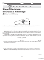
EXPERIMENT 13
/ Simple Machines: Mechanical Advantage
D. Wheel and Axle
B. Lever
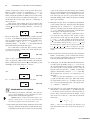
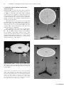
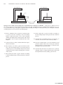
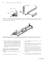
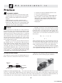
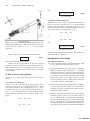
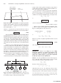
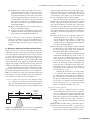
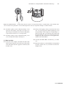
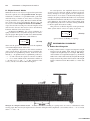
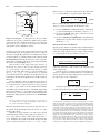
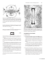
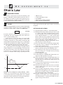
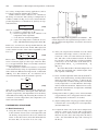
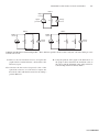
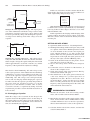
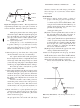
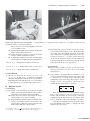
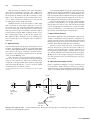
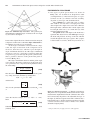
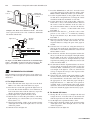
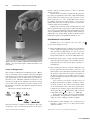
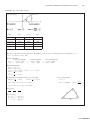
The combination of a wheel and axle has many practical applications. For example, when you open a door by
turning a doorknob, you are using a wheel and axle. This
simple machine consists of a wheel fixed to a shaft or axle
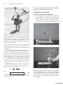
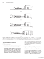
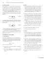
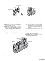
with the same axis of rotation (● Fig. 13.5a). Essentially, it
is equivalent to a lever with unequal lever arms.
A force Fi applied tangentially to the wheel with a
radius R can lift a load w (Fo) by means of a string or rope
wrapped around the axle (radius r). The AMA of the wheel
and axle is
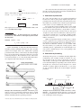
AMA 5
Fo
w
5
Fi
F
(13.10)
(wheel and axle)
In one revolution, the input force acts through a distance
2pR and the output force through a distance of 2pr. For the
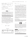
ideal, nonfictional case, Fidi 5 F(2pR) 5 Fodo 5 w(2pr),
and the TMA is
TMA 5
di
R
5
r
do
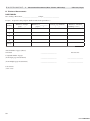
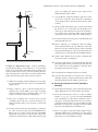
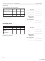
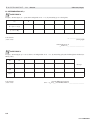
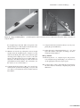
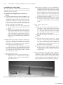
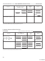
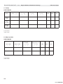
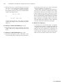
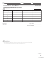
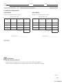
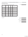
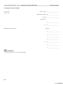
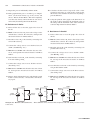
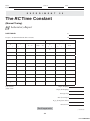
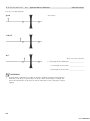
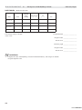
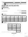
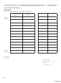
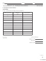
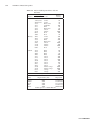
3. Use a load of 0.40 kg to 0.50 kg (or what is provided)
and record the mass in Data Table 2 and compute its
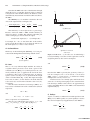
weight (in newtons, N). Assemble the lever as shown
in Fig. 13.2b using the pivot block, meter stick, and
load. The load should be on the table. (It may be necessary to tape the load to the stick.) Begin with the
fulcrum at the 50-cm mark (Li 5 Lo 5 50 cm).
4. Attach the spring scale to the stick at the end
opposite the load. (Tape or some other means may
be used here.) Then, pull vertically downward on
the scale with enough force so that the load moves
upward with approximately a constant speed. (Try
several pulls to get familiar with the equipment.
Also, it may be necessary to put the fulcrum block
near the edge of the table so as to have room to pull
the scale.)
Then, during a pull take a scale reading. (Your
lab partner should take the reading. Why?) Record in
Data Table 2. Repeat the procedure for a total of five
times, and then compute the average of the readings.
(13.11)
5. Repeat Procedure 4 for Li 5 60 cm, 70 cm, and 80 cm.
(wheel and axle)
6. Compute the AMA and the TMA for each case.
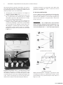
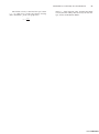
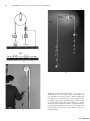
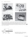
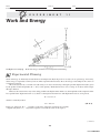
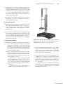
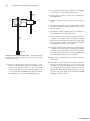
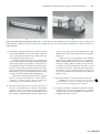
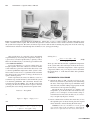
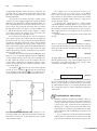
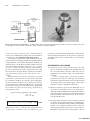
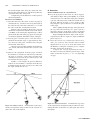
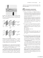
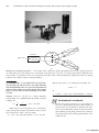
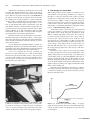
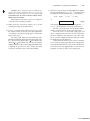
A practical application of a wheel and axle is shown in
Fig. 13.5b, along with an experimental setup.
In measuring the force to determine the AMA of
a wheel and axle, it is convenient to use the static equilibrium case, as for the pulley system in Section C of the
experimental procedures.
EXPERIMENTAL PROCEDURE
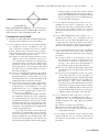
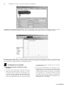
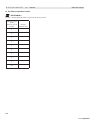
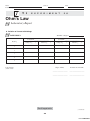
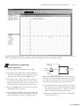
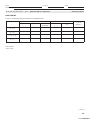
A. Inclined Plane
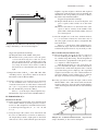
The AMA of an inclined plane is somewhat difficult to
determine experimentally. That is, manually determine Fi
by pulling a load up the incline at a constant speed with a
spring scale. So, for this simple machine the focus will be
on the TMA. This is given by
TMA 5 1/sin u
where u is the angle of incline.
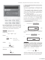
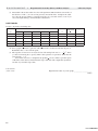
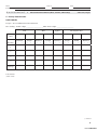
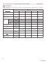
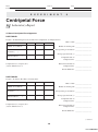
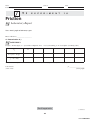
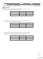
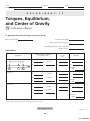
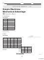
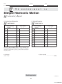
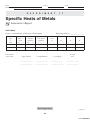
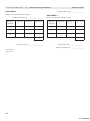
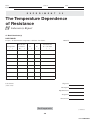
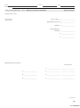
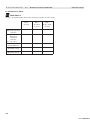
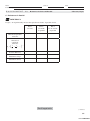
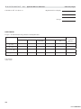
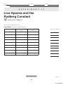
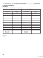
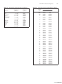
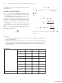
1. Several angles are listed in Data Table 1. Compute the
TMA for each angle.
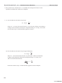
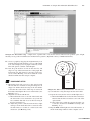
2. Plot a graph of TMA versus u and comment on the
result. Compute the TMA for u 5 90°. What does this
tell you?
7. Compute the efficiency for each case.
C. Pulleys
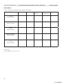
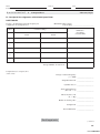
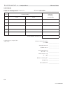
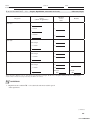
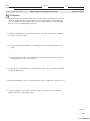
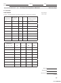
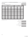
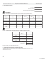
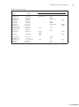
8. Determine the mass of one of the single pulleys and
one of the multiple-sheave pulleys on a laboratory
balance, and record in Data Table 3. These pulleys
will be used as the movable pulleys in the following
situations, and their weights must be included in the
loads.
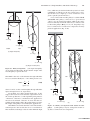
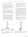
9. Assemble a single fixed pulley as illustrated in
Fig. 13.3a, with enough weights on the force input
hanger so that it moves downward with a slow uniform
speed when given a slight tap. (A single pulley or one
pulley of multiple sheaves may be used.) Record the
forces due to these masses in Data Table 3.
10. The next step is to measure the distances di (or hi) and
do (or ho) with a meter stick. Pull down the weight
hanger supplying the input force F a distance (di) of
20 cm or more, and note the distance the load moves
upward (do). Record these distances in Data Table 3.
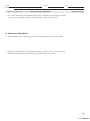
11. Calculate the AMA, TMA, and efficiency (e) for
this case.
www.ATIBOOK.ir