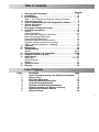
1
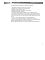
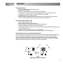
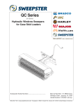
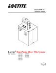
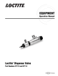
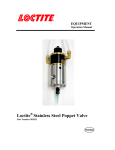
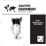
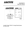
EQUIPMENT OPERATION MANUAL PRODUCT RESERVOIR Loctite® Series 9000 Rotospray System FULL ADD 1 LITER ADD 2 LITERS Pump 983330 Reservoir 982880 Head 983600-983621 ADD 3 LITERS BEAD OF LOCTITE PRODUCT DISPENSED BY NON-CONTACT MEANS INSIDE A BORE. ROTOSPRAY HEAD ROTOSPRAY PUMP Table of Contents 1 2 3 4 5 6 7 8 9 10 11 12 13 14 15 16 Page No. Warnings and Precautions . . . . . . . . . . . . . . . . . . . . . . . . . . . . .2 Introduction . . . . . . . . . . . . . . . . . . . . . . . . . . . . . . . . . . . . . . . . .3 Items Supplied . . . . . . . . . . . . . . . . . . . . . . . . . . . . . . . . . . . . .4,5 Table 1 - List of Rotospray Heads with Spinner Diameter . . . . . . . .4 Theory of Operation . . . . . . . . . . . . . . . . . . . . . . . . . . . . . . . . . . .6 View of Rotospray System with Components Labeled . . . . . . . .7 Spinner Information . . . . . . . . . . . . . . . . . . . . . . . . . . . . . . . . . . .8 Spinner Selection . . . . . . . . . . . . . . . . . . . . . . . . . . . . . . . . . . . . . .8 Description of Required Controls . . . . . . . . . . . . . . . . . . . . . . . .9 Installation Instructions . . . . . . . . . . . . . . . . . . . . . . . . . . . . . . .10 General . . . . . . . . . . . . . . . . . . . . . . . . . . . . . . . . . . . . . . . . . . . .10 Tubing Connections . . . . . . . . . . . . . . . . . . . . . . . . . . . . . . . . . . .11 Initial Feed Tube to Spinner adjustment . . . . . . . . . . . . . . . . . . . .12 Reservoir Mounting Dimensions . . . . . . . . . . . . . . . . . . . . . . . . . .13 Pump Mounting Dimensions . . . . . . . . . . . . . . . . . . . . . . . . . . . . .14 Rotospray Head Mounting Dimensions . . . . . . . . . . . . . . . . . . . . .15 Dispense Location and Spinner Overhang . . . . . . . . . . . . . . . . . .16 Table 2 - Spinner Diameter vs. Overhang . . . . . . . . . . . . . . . . . . .16 Operation . . . . . . . . . . . . . . . . . . . . . . . . . . . . . . . . . . . . . . . . . .17 Maintenance . . . . . . . . . . . . . . . . . . . . . . . . . . . . . . . . . . . . . . . .19 Troubleshooting . . . . . . . . . . . . . . . . . . . . . . . . . . . . . . . . . . . . .20 General . . . . . . . . . . . . . . . . . . . . . . . . . . . . . . . . . . . . . . . . . .20,21 Replacement Parts and Assemblies . . . . . . . . . . . . . . . . . . .22-25 Telephone Numbers for Help . . . . . . . . . . . . . . . . . . . . . . . . . . .26 Specifications . . . . . . . . . . . . . . . . . . . . . . . . . . . . . . . . . . . . . . .27 Dimensions . . . . . . . . . . . . . . . . . . . . . . . . . . . . . . . . . . . .13,14,15 Utilities Required . . . . . . . . . . . . . . . . . . . . . . . . . . . . . . . . . . . . .27 Weights . . . . . . . . . . . . . . . . . . . . . . . . . . . . . . . . . . . . . . . . . . . .27 Quick Info Sheet . . . . . . . . . . . . . . . . . . . . . . . . . . . . . . . . . . . . .28 Warranty . . . . . . . . . . . . . . . . . . . . . . . . . . . . . . . . . . . . . . . . . . .29 List of Figures Figure 1 2 3 4 5 6 7 8 9 Description Page View of Rotospray System with Components Labeled 7 Spinner Types 8 Feed Tube Adjustment 12 Reservoir Mounting Dimensions 13 Pump Mounting Dimensions 14 Rotospray Head Mounting Dimensions 15 Dispense Location and Spinner Overhang 16 Adjusting the Dispense Amount 17 Quick Info Sheet 28 1 1 Warnings and Precautions • OBSERVE ALL WARNINGS. READ and UNDERSTAND all instructions in the manual before attempting to install and operate this equipment. • This equipment has been designed and tested for use with Loctite® anaerobic products. • DO NOT USE equipment for other than intended use. • BE SURE that all adhesives, solvents, or fluids used are chemically compatible with the wetted parts of the equipment. • ALWAYS READ the Material Safety Data Sheet(s) before using adhesives, solvents, or any other chemicals in this equipment. COMPLY with ALL WARNINGS and SAFETY INSTRUCTIONS AS STATED. • ALWAYS WEAR protective eyewear, gloves, clothing, and respirator as recommended in this manual or the Material Safety Data Sheet(s). • Any misuse of the equipment or accessories, such as over-pressurizing, modifying parts, using incompatible chemicals, adhesives, or worn, damaged or not recommended parts, can cause rupture or breakage and result in fluid injection, splashing in the eyes or on the skin, or other serious injury or property damage. • NEVER alter or modify any part of this equipment. Doing so could result in a malfunction and will void your warranty. • CHECK the equipment regularly and repair or replace worn or damaged parts immediately. • NEVER exceed the recommended working pressure or the maximum air inlet pressure stated on the equipment or in the manual. • Properly ground all electrical components as recommended in the manual or technical data. • Always KEEP HANDS and FINGERS away from moving parts to reduce the risk of injury. • ALWAYS RELIEVE any pressure and turn off all power sources when checking or servicing any part of the equipment to reduce the risk of serious injury. • RETAIN THIS MANUAL FOR FUTURE REFERENCE. 2 2 Introduction This manual covers the Loctite® Series 9000 Rotospray System. Manual part no. 983355 has detailed information on the Loctite® Rotospray Pump. Manual part no. 982894 has detailed information on the Loctite® Rotospray Reservoir. The Loctite Series 9000 Rotospray System consists of the following components: 1. A Rotospray Centrifugal Force Dispense Head. 2. The Loctite Rotospray Pump. 3. The Loctite Rotospray Reservoir. Various spinner diameters and types are available. Table 1 on page 4 has a tabulated list of Rotospray Heads and spinner types and diameters. See Spinner Information on page 8 for spinner type descriptions. Customer-supplied, electro-pneumatic or pneumatic controls operate the system. See page 9 for control system requirements. The Rotospray Head can be mounted horizontally or with the spinner vertically down depending on spinner type. The Loctite Series 9000 Rotospray System is designed to dispense anaerobic materials with viscosity <100,000 centipoise that can be gravity fed to the pump. The pump displacement range is 0.02 cc to 0.45 cc. Typical Loctite Products are: Loctite product 271™, 277, 620, 635, 640, 11264, 11358, 11747, and 12019. The Loctite Series 9000 Rotospray System is a non-contact dispensing unit. The system uses a positive displacement pump and centrifugal force to apply a bead of Loctite adhesive or sealant into component bores or holes. Briefly, the system works like this: 1. The Loctite Rotospray Pump meters the Loctite Product onto a rotating disk near the center of the disk. 2. Centrifugal force spreads the Loctite Product across the disk surface in an even film. 3. When the Loctite Product reaches the edge of the disk, centrifugal force spins the film across the gap between the spinner OD and the hole ID. 4. The Loctite Product is applied as a bead or ring of Loctite Product to the ID of the hole. (See Theory of Operation section on page 6 for more details.) The centrifugal force feature allows a successful application into a hole that is slightly out of round, has machining chatter marks, is in an as cast condition, or has other internal features. Because this is a non-contact dispensing system, there is clearance between the spinner OD and hole ID. This feature allows a successful application even if the spinner is not in the exact center of the hole. 3 3 Items Supplied Note that the Rotospray Head, the Rotospray Pump, and the Rotospray Resevoir must be ordered as separate line items. A Loctite Series 9000 Rotospray System consists of the following components: 1. Qty (1) Rotospray Head from Table 1 below. Listing Item 1 2 3 4 5 6 7 8 9 10 11 12 13 14 15 16 17 18 19 20 21 22 Table 1 of Rotospray Head Part No., Spinner Type and Spinner Diameter Rotospray Head Part No. Spinner Type Spinner Diameter 983600 Horizontal 0.375 983601 Horizontal 0.437 983602 Horizontal 0.500 983603 Horizontal 0.625 983604 Horizontal 0.750 983605 Horizontal 0.875 983606 Horizontal 1.000 983607 Horizontal 1.250 983608 Horizontal 1.500 983609 Horizontal 1.750 983610 Horizontal 2.000 983611 Vertical Down 0.375 983612 Vertical Down 0.437 983613 Vertical Down 0.500 983614 Vertical Down 0.625 983615 Vertical Down 0.750 983616 Vertical Down 0.875 983617 Vertical Down 1.000 983618 Vertical Down 1.250 983619 Vertical Down 1.500 983620 Vertical Down 1.750 983621 Vertical Down 2.000 Qty. (1) Rotospray Head includes: Qty. (1) Packaging and Inserts. Qty. (1) Loctite Rotospray Head with air motor, spindle, spinner, and feed tube. Qty. (1) Air Line Kit. Qty. (1) Instruction manual 984518. 4 Items Supplied, cont. 2. Qty (1) Part No. 983330 Loctite Series 9000 Rotospray Pump that includes: Qty. (1) Packaging and Inserts. Qty. (1) Loctite Rotospray Pump consisting of pump section and actuator section. Qty. (1) Mounting Bracket (983335). Qty. (1) Feedline Accessory Kit (983356). Qty. (1) Air Line Kit (983482). Qty. (1) Instruction Manual (983355). 3. Qty (1) Part No. 982880 Rotospray Reservoir that includes: Qty. (1) Packaging and Inserts. Qty. (1) Reservoir. Qty. (1) Wall Mounting Bracket. Qty. (1) Reservoir Casement. Qty. (1) Sensor Mounting Bracket. Qty. (1) Parts Kit: (3) Reservoir outlet plugs. (4) Male elbows. (1) Tube Loctite® product PST®. Qty. (1) Instruction Manual (982894). 5 4 Theory of Operation The Loctite Series 9000 Rotospray System operates as follows: Refer to the Fig.1 on page 7. • A customer-supplied slide positions the Rotospray Head and spinner disk inside the bore to be treated. • Gravity feeds the Loctite Product from the Reservoir into the pump and the Pump has been cycled a sufficient number of times to fill the tubing between the pump and the Rotospray Head with Loctite Product. • The Air motor starts, rotating the spinner. • The Pump cycles, dispensing a metered amount of Loctite Product onto the rotating spinner disk. • Centrifugal force moves the product across the disk surface until it reaches the edge of the disk. • At the edge of the disk, centrifugal force spins the product across the gap between the edge of the disk and the ID of the part. • The Loctite Product is applied as a ring or bead within the part bore. • The air motor stops and the spinner stops rotating. • The pump piston retracts. • The customer-supplied slide returns the Rotospray Head and spinner disk to the home position. The Loctite Series 9000 Rotospray Pump is a pneumatically-operated piston pump. Adjusting the piston stroke controls the amount of product dispensed. The amount can be adjusted between 0.02 cc to 0.45 cc per stroke. See Loctite Manual 983355 for both a more detailed description of the Series 9000 Pump and an illustrated sequence of pump operation. 6 5 Component Identification PRODUCT RESERVOIR FULL OPTIONAL LOW LEVEL SENSOR ADD 1 LITER ADD 2 LITERS ADD 3 LITERS FEED TUBE PUMP STROKE ADJUSTER FEED TUBE ADJUSTMENT PUMP INLET SPINNER ROTOSPRAY HEAD PUMP OUTLET AIR MOTOR ROTOSPRAY PUMP Fig. 1 View of Rotospray System with Components Labeled. 7 6 Spinner Information The two basic spinner types available are illustrated below in Fig. 2. .10 INCH MINIMUM RADIAL CLEARANCE HORIZONTAL SPINNER BEAD LOCATION IN BORE VERTICAL SPINNER Fig 2. Spinner Types For the Series 9000 Rotospray System to operate successfully there must be a 0.10 inch (2.5 mm) radial clearance between the spinner OD and hole ID. This clearance is important with the smaller spinner diameters. If the clearance is too small, the Loctite Product will not separate from the spinner edge but rather bridge the gap between the spinner OD and hole ID and result in an unsatisfactory dispense. The Series 9000 Rotospray System with the smallest stock spinner of 0.375 inch diameter can be used to successfully dispense into a 9/16-inch (0.563 inch) (14.3 mm) minimum hole diameter. If the clearance between the spinner OD and hole ID is too great, the bead will not be well defined, i.e. a disconnected series of dots. Typically, the largest stock spinner of 2.00 inch diameter will successfully dispense into a 5.0 inch (125 mm) diameter hole. Multiple strokes of the Series 9000 Pump may be needed to deliver enough product. See the Spare Parts Listing on pages 24 and 25 for a complete list of stock spinner sizes. If a specific hole is outside the above ranges contact your Loctite Representative. Many Special Rotospray Systems have been built to dispense into holes both larger and smaller than the above limits. 8 7 Description of Required Controls The controls shall include components to accomplish the following: 1. 2. 3. 4. Start Dispense Cycle with part present and slide forward. Energize two 4-way solenoid valves for timed intervals. Generate a “dispense complete” signal. Interlock with both manual and automatic machine modes. The sequence of operation is as follows: 1. Part present and slide forward will indicate “time zero” for the dispense cycle. 2. At “time zero” energize solenoid #1 to start air motor. This starts the spinner rotating. 3. At time 0.5 seconds (this to allow air motor to reach full speed) energize solenoid #2, advancing pump piston. This will cause Loctite Product to be dispensed onto the rotating spinner. 4. At time 1.5 seconds de-energize solenoid #2, retracting pump piston. 5. At time 2.5 seconds de-energize solenoid #1, stopping the spinner rotation. 6. At time 3.0 seconds (this allows the air motor and spinner to come to a complete stop), generate a “dispense complete” signal. The slide can now retract. See the “Utilities Required “ section on page 27 for pneumatic valve flow requirements. 9 8 Installation Inspection before installation: The Loctite Rotospray System was inspected before shipment. Check the items in the shipping container against the Packing List. After removing the items from the shipping container(s), inspect them for visible damage. Promptly report any damaged or missing parts to both the shipper and your Loctite representative. CAUTION: DO NOT REMOVE ANY ITEMS THAT ARE SEALED IN PLASTIC BAGS UNTIL THEY ARE TO BE USED AS THEY MAY BECOME CONTAMINATED RESULTING IN PERFORMANCE PROBLEMS. Installation See figures 4, 5, 6 on pages 13, 14, 15 for mounting dimensions of reservoir, pump, and rotospray head. Reservoir Locate the reservoir so that: 1. The reservoir outlet is at least 12 inches (300 mm) above the pump inlet. 2. The pump is within range of the reservoir outlet tubing. Attach the Reservoir Bracket to a suitable surface using 1/4-inch diameter or 6 mm diameter screws. The hole pattern is shown in Fig. 4 on page 13. Pump Locate the pump so that: 1. The pump axis is horizontal. 2. The pump is at least 12 inches (300 mm) below the outlet of the gravity feed reservoir. 3. The pump is at approximately 4 inches (100 mm) below the center line of the Rotospray centrifugal force dispensing head. 4. There is enough clearance to allow easy access to the outlet fitting. 5. There is enough clearance to allow easy access to the control air fittings. 6. The Rotospray centrifugal force dispensing head is within the range of the pump outlet tubing. Secure the Pump Mounting Bracket (Part no. 983335) to the mounting surface with 5/16-inch diameter or 8 mm diameter screws. The hole pattern is given in Fig. 5 on page 14. Install the pump assembly into the Mounting Bracket. Rotospray Head Attach the Rotospray Head to the slide or other mounting detail using 1/4-inch diameter or 6 mm diameter screws. The hole pattern is shown in Fig. 6 on page 15. 10 Installation, cont. Connecting Air and Product Lines: 1. Reservoir 1.1. Install the fittings and plugs as required by the specific application. 1.2. Apply Loctite® 565 PST® to the threads of the fittings or plugs as follows: The first (3±1) fitting threads are left bare to allow easy starting into the reservoir outlet threads. The PST® is applied to the next (3±1) threads 1.3. Screw the fittings or plugs into the reservoir outlet threads and tighten to 20±2 inch pounds torque. 1.4. Insert the 3/8-inch OD tubing into the outlet fitting and tighten the fitting nut 2 to 2 1/2 turns past finger tight. 1.5. If the reservoir is supplied with the optional Low Level Sensor, install and adjust the sensor per the Loctite Reservoir Manual part no. 982894. 2. Pump 2.1. Install air line fittings into the 1/8 NPT ports in the pneumatic actuator and tighten to 60±10 inch pounds torque. 2.2. Connect air line from the normally not passing control valve port to the actuator port closest to the adjustment knob; (“Dispense” port on actuator). 2.3. Connect air line from the normally passing control valve port to the actuator port farthest from the adjustment knob; (“Retract” port on actuator). 2.4. Connect 3/8-inch OD tubing from the product reservoir to the pump inlet and tighten the fitting nut 2 to 2 1/2 turns past finger tight. 2.5. Connect 1/4-inch OD tubing from the pump outlet to the applicator being used. Tighten both fitting nuts 2 to 2 1/2 turns past finger tight. 3. Rotospray Head Note that the Air Inlet Fitting of the air motor is also a flow restrictor to limit air motor RPM. Do not operate the device without this fitting in place. Do not replace this fitting with anything other than the specified Loctite part number. 3.1. Connect the air line from the normally not passing port of the air motor control valve to the fitting installed at the “IN” (inlet) port on the air motor. 3.2. Connect the air line from the fitting installed at the “EXH” (exhaust) port on the air motor to a suitable silencer-reclassifier. 3.3. Connect the product tubing from the pump outlet to the feed tube connector on the rotospray if not already done per Step 2.5 above. 11 Installation, cont. Initial Feed Tube to Spinner Adjustment The feed tube end on a new rotospray head is supplied cut to the correct angle and set at the correct clearance as shown in Fig. 3 below. If for some reason the feed tube end is out of adjustment, readjust per the following steps. Feed Tube Liner Stickout The plastic feed tube liner should extend approximately 0.19 inches beyond the end of the metal support tube. Radial Adjustment 1. View the spinner from the air motor side. 2. Loosen the two feed tube adjustment nuts. 3. Rotate the feed tube to the between the 12:30 to 12 o’clock position. 4. Hand tighten the two feed tube adjustment nuts. Axial Adjustment Use the two adjustment nuts to move the feed tube axially to get the clearance as shown in Fig. 3 below. Measure the clearance with non-metallic shim stock. Do not use brass shim stock as traces of brass may cause anaerobic product curing. With the adjustment complete, tighten the nuts. ADJUSTMENT NUTS 30° A .020 ±.005 A A A 12:00 12:3 0 FEED TUBE ADJUSTMENT HORIZONTAL ROTOSPRAY .020 FEED TUBE ADJUSTMENT VERTICAL ROTOSPRAY SECTION A-A RADIAL FEED TUBE POSITION (TYPICAL) Fig. 3 Feed Tube Adjustment 12 15° ±.005 Installation, cont. 6.25 8.64 7.28 9.35 9.00 TOP VIEW MOUNTING HOLE PATTERN NOTE: MOUNTING SLOTS ARE CLEARANCE FOR 1/4-INCH OR 6 mm SOCKET HEAD CAP SCREWS ONE LITER REFILL 20.25 FULL ADD 1 LITER 12.88 ADD 2 LITERS ADD 3 LITERS 1.2 2.38 BOLT CIRCLE SENSOR REF. ONLY SECTIONAL VIEW FRONT VIEW (WITH LID CLOSED) Fig. 4 Reservoir Mounting Dimensions. 13 Installation, cont. 2.50 .50 2.50 2.06 4.20 1.63 REF. .44 .38 1.50 .50 1.88 DIAMETER .34 DIAMETER 7/16 HEX 9.15 1.35 DIAMETER Fig. 5 Series 9000 Pump Mounting Dimensions. 14 Installation, cont. 4.56 DIMENSIONS TO SLOT CENTER LINES 1.50 1.88 CENTRAL .28 TYP. 1.00 TYP. MOUNTING SLOT DIMENSIONS 11.47 5.12 4.00 IN IN EXH INLET FITTING CONTAINS AIR FLOW RESTRICTOR TO LIMIT SPINNER RPM. DO NOT OPERATE DEVICE WITHOUT THIS FITTING. IF INLET FITTING IS REPLACED, IT SHALL BE REPLACED WITH FITTING OF IDENTICAL LOCTITE PART NUMBER. 2.50 4.38 2.00 .500/.502 x .25 DP. KEYWAY Fig. 6 Series 9000 Rotospray Head Mounting Dimensions. 15 Installation, cont. Dispense location and spinner overhang For all of the listed Rotospray Heads, the dispense location is four (4) inches from the front of the spindle housing. DISPENSE LOCATION HORIZONTAL MOUNTING 4.00 4.00 .21 SPINNER OVERHANG DISPENSE LOCATION VERTICAL MOUNTING Fig. 7 Dispense Location and Spinner Overhang The Dispense Location is four (4) inches from the front of the spindle housing for all the Rotospray Heads covered in this manual. The Spinner Overhang for horizontal mounting units is 0.0 inch. The Spinner Overhang for vertical down mounting varies with the spinner diameter per Table 2 (below). Table 2 Listing of Rotosprays, Spinner Diameters & Spinner Overhangs Part No. Spinner Dia. (in.) Spinner Overhang (in.) 983611 .375 0.163 983612 .437 0.171 983613 .500 0.167 983614 .625 0.183 983615 .750 0.192 983616 .875 0.209 983617 1.000 0.225 983618 1.250 0.242 983619 1.500 0.276 983620 1.750 0.309 983621 2.000 0.343 16 9 Operation Filling the Reservoir 1. Open the one liter bottle of Loctite Product. 2. Open the Reservoir Lid. 3. Pour the Loctite Product from the bottle into the Reservoir. 4. The bottle can be left in place above the Reservoir to drain into the reservoir. This empties the maximum amount of Loctite Product from the bottle. 5. The Reservoir capacity is four (4) liters. 6. When a bottle is removed from the filling position, the Reservoir lid will self-close by gravity. The lid prevents contaminants from falling into the Reservoir. Priming the Pump (first time use) 1. Fill the reservoir with product. 2. Set the pump stroke to 3/4 of maximum. 3. Use the “Manual” control functions to retract the pump piston. 4. Disconnect the 3/8-inch OD tube from the pump inlet. 5. Let the product flow to within 1/2-inch of the end of the 3/8-inch tube, then reconnect the tube to the pump inlet. 6. Use the “Manual” control functions to cycle the pump. 7. Continue to cycle the pump until air-free product flows at the dispense point. Adjusting the amount of Loctite Product dispensed The stroke adjuster knob on the the pump controls the amount of product dispensed per pump cycle. Start with the knob open one turn counter clockwise from the “zero-stroke” position. Cycle the pump and measure the amount of product dispensed. Adjust the knob per Fig. 8 below until the desired amount is dispensed. The plus (+) and minus (-) arrows on the stroke adjuster knob indicate the volume increase and decrease directions. MORE LESS STROKE ADJUSTER KNOB Fig. 8 Adjusting the Dispense Amount 17 Operation, cont. Final Check 1. Position the spinner inside a part. 2. Cycle the Rotospray through one dispense cycle. 3. Adjust the Quantity of Loctite Product, if necessary. 4. Adjust the position of the dispensed bead, if necessary. 5. The system is ready for automatic operation. 18 10 Maintenance Routine 1. Inspect air tubing, product tubing, and fittings for cracks, kinks or breaks and replace, as required. 2. Drain the air line filter bowl, if necessary. 3. Refill the air motor lubricator, as required. 4. Refill the Loctite Product Reservoir, as required. Idle Time 1. If the system is in daily use, you do not need to service the pump, product tubing, or reservoir to prevent product curing unless a contaminant is introduced into the system. 2. The pump and tubing can be left idle for as long as one (1) month without curing under normal temperature (70° - 80°F). 3. If the system is to be idle for longer than one (1) month, both the pump, the product lines and the feed tube should be serviced. Remove and replace product the feed lines and the feed tube. Return the pump to a Loctite Service Center for cleaning and/or rebuilding. See the pump manual Loctite part no. 983355 for more information. 4. If the system is to be idle for longer than one (1) month, then the product reservoir, its fittings and feed lines should be replaced. See the reservoir manual Loctite part no. 982894 for more information. 19 11 Troubleshooting Possible problems and solutions for the Series 9000 Rotospray Pump. Troubleshooting Guide Problem Cause Solution Pump does not dispense product and the Stroke Adjuster Knob does not move when the pump is cycled. No air supply. Low air pressure. Turn on air supply. Adjust air pressure to at least 60 psig. Reset Stroke Adjuster Knob. Pump does not dispense product and the Stroke Adjuster Knob moves very slowly when the pump is cycled. Pump does not dispense product but the Stroke Adjuster Knob moves normally when the pump is cycled. Product leaks from dispenser. Stroke Adjuster Knob set to zero stroke. Pump air actuator defective. Control valve faulty. Control logic problem. Cured product in pump. Cured product in outlet tubing or applicator. Product reservoir empty. Pump is air bound. Cured product in inlet tubing or fittings. Pump check valve defective. Pump check valve defective. Dispenser is located at a lower level than the pump. Air in product. Pump outlet tubing too long. Pump outlet tubing expands on pump cycling. All four (4) Items just above. 20 Replace actuator. Replace control valve. Check program and components. Replace pump. Replace tubing or applicator. Refill reservoir. Reprime pump and check pump inlet fittings. Replace tubing or fittings. Replace pump. Replace pump. Reposition pump so that it is about 4 inches (100 mm) below the dispenser. Do not shake product bottle before filling reservoir. Mount pump as close as possible to dispenser. Change original 1/4-inch OD polyethylene tubing to 1/4-inch OD nylon tubing. See Replacement parts on pages 22-25. Modify process to reduce drool. Change timing on rotospray spin time to get clean dispenses. Troubleshooting, cont. Possible problems and solutions for the Series 9000 Rotospray System. Problem Troubleshooting Guide Cause Air motor does not run but product dispenses normally. No air supply. Low air pressure. Control valve faulty. Control logic problem. Air in Loctite Product. Poor dispensed bead geometry. Air motor frozen due to lack of lubrication. Loose fittings on inlet side of pump or outlet side of reservoir. Kinks or loops in product feed line allowing an air pocket to form. Air trapped in product during reservoir filling. Air entrained in product through shaking or agitation. Feed tube out of position. Air motor RPM too low. Spinner located off hole centerline. Spinner OD too close to hole ID. Solution Turn on air supply. Adjust air pressure to at least 60 psig. Replace control valve. Check program and components. Replace air motor and refill air motor lubricator. Tighten fittings or replace fittings. Reposition feed line with uniform slope so there are no kinks or loops. Fill reservoir slowly. Allow product to remain at rest so that entrained air can rise to top and escape. Consult Loctite Technical Information about vacuum degassing procedures. Position feed tube per instructions on page 12. Increase RPM by adjusting air pressure to at least 60 psig. Ensure that air motor is being lubricated by checking lubricator function. Reposition either the part or the Rotospray Head. Use a smaller spinner and feed tube set. Consult Loctite Technical Information about special spinners. 21 12 Replacement Parts and Assemblies The following is a list of recommended parts or assemblies that may be required to service the Series 9000 Rotospray System. Reservoir Replacement Parts: Description Loctite® Product 565 PST® 50 ml tube Product Reservoir Kit Reservoir casement Kit AC Level Sensor Kit DC Level Sensor Kit Loctite Part No. 56531 982881 982882 982716 950395 Qty. 1 1 1 As Req’d. As Req’d. Loctite Part No. 983117 983116 981821 981866 991733 999635 983335 993349 Qty. 1 1 10 m 10 m 1 1 As Req’d. 1 993553 1 Pump Replacement Parts: Description Pump assembly. Actuator Assembly Tubing 1/4-inch OD poly (for pump outlet). Tubing 3/8-inch OD poly (for pump inlet). Male connector, 1/4 T x 1/8 NPT, nylon Male connector, 3/8 T x 1/4 NPT, nylon Mounting Bracket Male Connector, 1/4 T x 1/8 NPT, Stainless Steel (for pump outlet) Male Connector, 3/8 T x 1/4 NPT, Stainless Steel (for pump inlet) 22 Replacement Parts and Assemblies, cont. Series 9000 Pump Rebuilding Program: The Series 9000 Pump is not field serviceable. Our rebuilding process ensures that the pump is free of contaminants and assembled to proper specifications, reducing the possibly of a premature failure or unsatisfactory performance with Loctite products. This is accomplished by: • Ultrasonically cleaning the parts in the proper solvents for a predetermined time. • Treating all the wetted components to ensure a passive surface. • Using proper replacement parts. • Reassembling the pump in a clean room environment using proper techniques and torque specifications. To participate in this program, you will need to purchase and have on hand a pump assembly. At the recommended time intervals, you should replace the current pump assembly with the new assembly and return the used pump to the Loctite Equipment Service Department. A rebuilt pump will be shipped to you within five to ten working days after the receipt of your purchase order. All parts and labor are included in the price given to you to rebuild your pump. The rebuilt pump carries a ninety-day warranty. For further information on participating in this rebuild program, please contact us at: Telephone: 1-800-LOCTITE (1-800-562-8483) or 860-571-5100. The Spare Parts Listing continues on next page. 23 Replacement Parts and Assemblies, cont. Rotospray Head Replacement Parts: The list below is for horizontal Rotospray Heads. See the list on the following page for spare parts for vertical down Rotospray Heads. Description Loctite Part No. Qty. Rotospray Drive Assembly complete less spinner and feed tube. 983622 1 Spinner, horizontal, 0.375 inch diameter Feed Tube Assembly for 0.375 inch diameter spinner 983635 983634 1 1 Spinner, horizontal, 0.437 inch diameter Feed Tube Assembly for 0.437 inch diameter spinner 983636 983634 1 1 Spinner, horizontal, 0.500 inch diameter Feed Tube Assembly for 0.500 inch diameter spinner 983637 983634 1 1 Spinner, horizontal, 0.625 inch diameter Feed Tube Assembly for 0.625 inch diameter spinner 983638 952743 1 1 Spinner, horizontal, 0.750 inch diameter Feed Tube Assembly for 0.750 inch diameter spinner 983639 952743 1 1 Spinner, horizontal, 0.875 inch diameter Feed Tube Assembly for 0.875 inch diameter spinner 983640 952743 1 1 Spinner, horizontal, 1.00 inch diameter Feed Tube Assembly for 1.00 inch diameter spinner 952744 952743 1 1 Spinner, horizontal, 1.25 inch diameter Feed Tube Assembly for 1.25 inch diameter spinner 983642 983657 1 1 Spinner, horizontal, 1.50 inch diameter 983643 Feed Tube Assembly for 1.50 inch diameter spinner 983657 1 1 Spinner, horizontal, 1.75 inch diameter 983644 Feed Tube Assembly for 1.75 inch diameter spinner 983657 1 1 Spinner, horizontal, 2.00 inch diameter 983645 Feed Tube Assembly for 2.00 inch diameter spinner 983657 1 1 Spare Parts Listing continued on next page. 24 Replacement Parts and Assmblies, cont. Rotospray Head Replacement Parts: The list below is for vertical down Rotospray Heads. See the list on the preceding page for spare parts for horizontal Rotospray Heads. Description Loctite Part No. Qty. Rotospray Drive Assembly complete less spinner and feed tube assembly. 983622 1 Spinner, vertical down, 0.375 inch diameter Feed Tube Assembly for 0.375 inch diameter spinner 983646 983634 1 1 Spinner, vertical down, 0.437 inch diameter Feed Tube Assembly for 0.437 inch diameter spinner 983647 983634 1 1 Spinner, vertical down, 0.500 inch diameter Feed Tube Assembly for 0.500 inch diameter spinner 983648 983634 1 1 Spinner, vertical down, 0.625 inch diameter Feed Tube Assembly for 0.625 inch diameter spinner 983649 952743 1 1 Spinner, vertical down, 0.750 inch diameter Feed Tube Assembly for 0.750 inch diameter spinner 983650 952743 1 1 Spinner, vertical down, 0.875 inch diameter Feed Tube Assembly for 0.875 inch diameter spinner 983651 952743 1 1 Spinner, vertical down, 1.00 inch diameter Feed Tube Assembly for 1.00 inch diameter spinner 983652 952743 1 1 Spinner, vertical down, 1.25 inch diameter Feed Tube Assembly for 1.25 inch diameter spinner 983653 983657 1 1 Spinner, vertical down, 1.50 inch diameter Feed Tube Assembly for 1.50 inch diameter spinner 983654 983657 1 1 Spinner, vertical down, 1.75 inch diameter Feed Tube Assembly for 1.75 inch diameter spinner 983655 983657 1 1 Spinner, vertical down, 2.00 inch diameter 983656 Feed Tube Assembly for 2.00 inch diameter spinner 983657 1 1 25 13 Telephone Numbers for Help Telephone Numbers for Help: Questions regarding installation, operation, or safety should be addressed to: Henkel Corporation Technical Information Department 1001 Trout Brook Crossing Rocky Hill, Connecticut 06067 U.S.A. Telephone: 1-800-LOCTITE (1-800-562-8483) or 860-571-5100. 26 14 Specifications Dimensions: See the Figures listed below for dimensions: Figure Description Page 4 5 6 Reservoir Mounting Dimensions. Pump Mounting Dimensions. Rotospray Head Mounting Dimensions. 13 14 15 Weights: 982880 Loctite Rotospray Reservoir. 4.5 lbs. 14 lbs. When filled with 4 liters of Loctite anaerobic product. 983330 Loctite Series 9000 Rotospray Pump. 1.7 lbs. Loctite Series 9000 Rotospray Head. 4.4 lbs. (less product tubing and air hoses.) Utilities Required: 983330 Loctite Series 9000 Rotospray Pump. Compressed air: 60 psig to 90 psig., filtered to 5 microns, dry (no condensing moisture). Lubricated air not required. Compressed air usage is small, less than 1 scfm per stroke. Loctite Series 9000 Rotospray Head. Compressed Air: 60 psig to 80 psig., filtered to 5 microns, dry (no condensing moisture). Lubricated air: Use SAE #10 detergent automotive engine oil. Lubrication rate: (1) drop (1/30 cc or 0.002 in.3) per 50-75 scfm of air. A 0.002 in3 drop is a sphere of 0.156 inch dia. Locate mist type lubricator within 18 inches of air motor if possible and at a higher level than air motor. Avoid low spots in air hose, which act as oil trapping points. Air usage is 12 scfm at 60 psig., 15 scfm at 80 psig. 27 28 OIL INJ. ADD 3 LITERS ADD 2 LITERS 1) SLIDE ADVANCES ROTOSPRAY INTO POSITION (.5 SEC.) 2) ROTOSPRAY AIR MOTOR STARTS (.5 SEC.) 3) PUMP CYCLES AND DISPENSES PRODUCT (1.0 SEC.) 4) ROTOSPRAY DISPENSES INTO BORE (1.5 SEC.) 5) ROTOSPRAY STOPS (1.0 SEC.) 6) SLIDE RETRACTS ROTOSPRAY TO HOME POSITION (.5 SEC.) ROTOSPRAY CYCLE THE ROTOSPRAY 9000 APPLICATOR IS POWERED BY AN AIR MOTOR WITH 1/4 INCH INLET AND EXHAUST AIR LINES. SPEED IS LIMITED TO APPROXIMATELY 7000 RPM BY A BUILT IN FLOW RESTRICTOR IN THE AIR INLET FITTING. AIR CONSUMPTION IS LESS THAN 15 SCFM AT 80 PSIG. THE AIR MOTOR MUST BE LUBRICATED WITH A DETERGENT SAE #10 ENGINE OIL AT A RATE OF ONE DROP FOR EVERY 50-75 SCFM OF AIR. THE ROTOSPRAY WILL DISPENSE INTO HOLES FROM 9/16 INCH TO 5.0 INCH DIAMETER AND AT ANGLES FROM VERTICAL DOWN TO 10 DEGREES ABOVE HORIZONTAL DEPENDING ON SPINNER USED. THE ROTOSPRAY 9000 PUMP IS A MODULAR, GRAVITY FED, SELF PRIMING, POSITIVE DISPLACEMENT PUMP FOR DISPENSING LOCTITE ANAEROBIC PRODUCTS. THE PUMP IS PNEUMATICALLY OPERATED BY A CUSTOMER SUPPLIED 4-WAY VALVE. THE DISPENSED VOLUME CAN BE ADJUSTED BETWEEN .02 AND .45 GRAMS BY CHANGING THE PUMP STROKE. MULTIPLE STROKES CAN BE USED FOR LARGER VOLUMES. BEST DISPENSE CONTROL IS ACHIEVED BY MOUNTING THE PUMP AS CLOSE TO THE DISPENSE POINT AS POSSIBLE (LESS THAN 12 INCHES IS IDEAL), HOWEVER DISTANCES UP TO 8 FEET WILL WORK. FILTERED DRY AIR (5 MICRON) AT MINIMUM 60 PSIG AND MAXIMUM 90 PSIG IS REQUIRED. NO LUBRICATION IS REQUIRED. REFER TO PUMP MANUAL WHEN REPLACING MODULES OR DAMAGE WILL OCCUR. A CUSTOMER SUPPLIED MUFFLER/RECLASSIFIER SHOULD BE USED TO LIMIT AIR MOTOR EXHAUST NOISE AND REMOVE OIL FROM AIR. CUSTOMER SUPPLIED INJECTOR TYPE LUBRICATOR FOR AIR MOTOR SHOWN. INLINE LUBRICATOR CAN ALSO BE USED. FS OIL RESERVOIR FULL ADD 1 LITER THE FOUR LITER RESERVOIR CAN SUPPLY UP TO FOUR ROTOSPRAYS LOCATE RESERVOIR OUTLET PORT AT LEAST 12 INCH ABOVE PUMP INLET. USING A 3/8 INCH FEEDLINE, THE PUMP CAN BE MOUNTED UP TO 12 FEET AWAY FROM THE RESERVOIR. HOWEVER THE PUMP EFFICIENCY IS REDUCED AT THIS DISTANCE. THE RESERVOIR CAN BE SUPPLIED WITH OPTIONAL LOW LEVEL SENSORS OF 24 VOLT DC OR 110 VOLT AC. THE CUSTOMER MUST CONNECT THE LOW LEVEL SENSORS INTO HIS CONTROL SYSTEM. 15 Quick Info Sheet Fig. 9 16 Loctite Equipment Warranty Loctite expressly warrants that all products referred to in this Instruction Manual under Loctite Series 9000 Rotospray System (hereafter called “Products”) shall be free from defects in materials and workmanship. Liability for Loctite shall be limited, at its option, to replacing those Products which are shown to be defective either in materials or workmanship or to credit to the purchaser the amount of the purchase price thereof (plus freight and insurance charges paid therefor by the user). The purchaser’s sole and exclusive remedy for breach of warranty shall be such replacement or credit. A claim of defect in materials or workmanship in any Products shall be allowed only when it is submitted to Loctite in writing within one month after discovery of the defect or after the time the defect should have reasonably have been discovered and in any event, within twelve months after the delivery of the Products to the purchaser. No such claim shall be allowed in respect of Products which have been neglected or improperly stored, transported, handled, installed, connected, operated, used or maintained or in the event of unauthorized modification of the Products including; where products, parts or attachments for use in connection with the Products are available from Loctite, the use of products, parts or attachments which are not manufactured by Loctite. No Products shall be returned to Loctite for any reason without prior written approval from Loctite. Products shall be returned freight prepaid in accordance with instructions from Loctite. NO WARRANTY IS EXTENDED TO ANY EQUIPMENT THAT HAS BEEN ALTERED, MISUSED, NEGLECTED, OR DAMAGED BY ACCIDENT, OR IF THE SYSTEM IS USED TO DISPENSE ANY LIQUID MATERIAL OTHER THAN LOCTITE CORPORATION PRODUCTS. EXCEPT FOR THE EXPRESS WARRANTY CONTAINED IN THIS SECTION, LOCTITE MAKES NO WARRANTY OF ANY KIND WHATSOEVER, EXPRESS OR IMPLIED, WITH RESPECT TO THE PRODUCTS. ALL WARRANTIES OR MERCHANTABILITY, FITNESS FOR A PARTICULAR PURPOSE, AND OTHER WARRANTIES OF WHATEVER KIND (INCLUDING AGAINST PATENT OR TRADEMARK INFRINGEMENT) ARE HEREBY DISCLAIMED BY LOCTITE AND WAIVED BY THE PURCHASER. THIS SECTION SETS FORTH EXCLUSIVELY ALL OF LOCTITE LIABILITY TO THE PURCHASER IN CONTRACT, IN TORT OR OTHERWISE IN THE EVENT OF DEFECTIVE PRODUCTS. WITHOUT LIMITATION OF THE FOREGOING, TO THE FULLEST EXTENT POSSIBLE UNDER APPLICABLE LAWS, LOCTITE EXPRESSLY DISCLAIMS ANY LIABILITY WHATSOEVER FOR ANY DAMAGES INCURRED DIRECTLY OR INDIRECTLY IN CONNECTION WITH THE SALE OF USE OF, OR OTHERWISE IN CONNECTION WITH, THE PRODUCTS, INCLUDING, WITHOUT LIMITATION, LOSS OF PROFITS AND SPECIAL, INDIRECT OR CONSEQUENTIAL DAMAGES, WHETHER CAUSED BY LOCTITE NEGLIGENCE OR OTHERWISE. 29 Loctite Industrial Loctite Corporation 1001 Trout Brook Crossing Rocky Hill, CT 06067-3910 Loctite Automotive Technology Center 2455 Featherstone Road Auburn Hills, Michigan 48326 Loctite Canada Inc. 2225 Meadowpine Blvd. Mississauga, Ontario L5N 7P2 Loctite Company de México, S.A. de C.V. Calzada de la Viga s/n, Fracc. Los Laureles Loc. Tulpetlac, C.P. 55090 Ecatepac de Morelos, Edo. de México México Loctite Brazil Av. Prof. Vernon Krieble, 91 06690-11-Itapevi São Paulo-Brazil www.loctite.com Loctite, 271 and PST are trademarks of Loctite Corporation, U.S.A. © Copyright 2001. Loctite Corporation. All rights reserved. Data in this manual is subject to change without notice. P/N984518 Rev. E 12/07 A Company