1
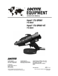
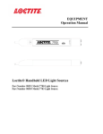
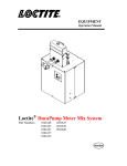
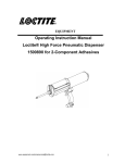
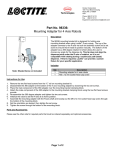
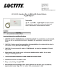
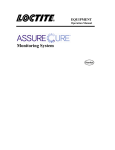
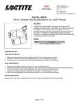
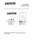
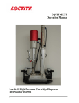
EQUIPMENT
Operation Manual
Loctite®
®
Zeta 7011-A Dosimeter-Radiometer for UVA
Part Number 98086
®
Zeta 7011-V Dosimeter-Radiometer for UVV
Part Number 98089
Table of Contents
1 Please Observe the Following
1.1 Emphasized Sections
1.2 For Your Safety
1.3 Items Supplied
2 Description
2.1 Basic Data about Operation
1
1
1
1
2
3
3 Technical Data
5
3.1 Specification
3.2 Calibration
5
6
4 Installation
4.1 Unpacking and Inspection
4.2 Installation and Start-up
5 Operation
5.1 One Button Operation Mode
5.2 Two Button Operation Mode
5.3 Additional Information Available in First Display Mode
5.4 Additional Information Available in Third Display Mode
5.5 Auto-shut off and Signs of Over Heating
6
6
6
7
7
7
8
9
9
6 Troubleshooting
10
7 Care and Maintenance
10
7.1 Maintenance
8 Warranty
10
11
1
Please Observe The Following
Emphasized Sections
1.1
Warning!
Refers to safety regulations and requires safety measures that protect the operator or
other persons from injury or danger to life.
Caution!
Emphasizes what must be done or avoided so that the unit or other property is not
damaged.
Notice:
Gives recommendations for better handling of the unit during operation or
adjustment as well as for service activities.
1.2
For Your Safety
Caution! IMPORTANT! Do not operate the unit before reading this section.
The Radiometer will be used to measure the UV Dose (energy) and UV Irradiance
inside UV curing equipment.
1. UV protective glasses with side shields should be worn when working with and
around the UV curing system.
2. Potentially exposed skin should be covered. Long sleeves and protective gloves
should be worn when measuring dose and irradiance in the UV curing system.
3. Never look directly at the UV radiation source.
1.3
List of Parts Supplied
®
Zeta 7011 Dosimeter-Radiometer
Operation Manual
2
Description
The Dosimeter-Radiometer measures the UV Dose (energy) and UV Irradiance
inside the UV curing equipment. The Dosimeter-Radiometer is traceable to the
National Institute of Standards and Technology (NIST). Spectral correction
coefficients are implemented to use the Dosimeter-Radiometer with a broad band
UV lamps. Units of measurement for the UV Dose (energy) are Joules per square
2
centimeter (J/cm ) and units for UV Irradiance are Watts per square centimeter
2
(W/cm ).
DO NOT EXPOSE THIS SIDE TO LIGHT
A
0.00
0.000
J/cm2
LCD
Display
MAX
W/cm2
Power
Button
Mode
Button
Power
Mode
7011-A
Dosimeter - Radiometer
Housing
Item #98086
Figure 1. Display Side of Dosimeter-Radiometer.
HOUSING
SENSOR LOCATION
BACK COVER
BACK COVER RETAINING SCREWS
Figure 2. Sensor Side of Dosimeter-Radiometer.
SENSOR OPENING
THERMO
INSULATION
BACK COVER
MOUNTING HOLES
+
+
-
S/N: UVS-00007
BATTERY COMPARTMENT
LIFT THERMO COVER
CUTOUT FOR ACCESS
HOUSING
Note: Two 1.5V AAA Batteries, User Installed (Not Supplied)
Figure 3. Sensor side of Dosimeter-Radiometer with cover removed to change
batteries
2
Description (continued)
During measurements the side with the “Power” button, the “Mode” button, and
the LCD display should be directed away from the UV radiation inside the UV
curing equipment to prevent the LCD display from being damaged.
CAUTION!
Exposing the LCD display to high intensity UV radiation will cause irreversible
LCD damage. When taking measurements, be certain the LCD display side is
facing away from light source. Also, the detector side of the unit should not be
exposed to UV light for longer than 5 seconds or damage could occur.
2.1 Basic Data about Operation
The Dosimeter-Radiometer can be ordered in two variations to accommodate the
different spectral ranges:
®
Zeta 7011-A: UV A = 320 – 400nm
®
Zeta 7011-V: UV V = 420 – 500nm
A
A
0.00
0.000
J/cm2
MAX
W/cm2
LCD Screen 1
A
0.000
0.0
W/cm2
MAX
sec
LCD Screen 2
75.0
3.3
MAX °C
sec
LCD Screen 3
2
Description (continued)
The LCD display has three modes of operation. The first display mode (mode 1) is
activated after turning the power on and it shows the results from memory (the digits and
units of measurement are not blinking). The second display mode (mode 2) is active while
measuring, showing the results of current measurement during readings (the digits and
units of measurement are blinking). The third display mode (mode 3) becomes active
when current measurements are finished and shows the results of last finished
measurements and only the units of measurement are blinking.
The Dosimeter-Radiometer shows results of measurements on a display having two rows.
After the measurement is done, the dose and maximum irradiance can be seen
simultaneously.
The Dosimeter-Radiometer has an internal temperature sensor that measures and stores
the maximum internal temperature during exposure inside of the equipment. This feature
allows detecting excessively high temperature that can cause damage to the unit.
The Dosimeter-Radiometer memory stores the results of last measurement until the
beginning of next reading even when unit is turned off. After the beginning of a new
reading, the old data is replaced with the new results.
The Dosimeter-Radiometer has a simple and intuitive logic of operation that displays the
results of the last reading for five minutes if no new buttons are pressed. After five minutes
it turns off automatically, saving the last results in memory for possible future analysis.
A simple one-button mode of operation can be used if the customer needs to measure only
the dose and a maximum irradiance after each single reading (LCD Screen 1).
The two-button mode of operation allows seeing the dose (LCD Screen 1), the maximum
irradiance(LCD Screen 2), and the maximum temperature after readings and times in
seconds when maximum irradiance and maximum temperature were reached (LCD Screen
3).
3
Technical Data
3.1 Specifications
Loctite Model
Part Number
Function
Zeta® 7011-A, Zeta® 7011-V
98086 Zeta® 7011-A UVA 98089 Zeta® 7011-V UVV
Self contained, one channel measuring device for
reading UV energy and maximum irradiance inside UV
curing equipment. Available in UV- A or V.
LCD Display
Energy/ Dose Range
Operating Range
Irradiance Range
Accuracy
Spectral Response
Operating Temp. Range
Auto Shut Off
System Alarms
Electrical Power Required
Battery Life
Dimensions Lx W x D
Weight without batteries
Calibration
Warranty
Two rows of digits
2
0 to 250 Joules/cm
2
0.01 to 5W/cm
2
0.01 to 2W/cm
± 5% typical; ± 10% maximum
®
UV A = 320 – 400nm Zeta 7011-A UVA
®
UV V = 420 – 500nm Zeta 7011-V UVV
0-75°C internal temp. Maximum internal temp.
80°C.
After 5 minutes the unit will shut off if no
significant amount of energy is registered.
Two systems: 1.) Internal temp. over 75°C turns on
sound alarm. Internal temp. over 80°C during
exposure run turns unit off.
2.) Low battery indicator.
Two user-replaceable 1.5V AAA size alkaline
batteries (not included)
3000 readings or 2000 hours
102 mm x 102 mm x 13 mm (4" x 4" x 0.52" )
200 g (5.7 oz.)
NIST Traceable
With Spectral Correction
1 year
Note: For intensity measurements of LED devices emitting at the 405 nm
wavelength, the Zeta 7011-V meter can be used to determine LED degradation. However,
because the 405 nm wavelength is just outside the optimal absorbency range of the Zeta
7011-V, the reading could be lower than it actually is. Also, intensity readings from meter
to meter may vary. That is to say, if two meters are used to measure the same LED device,
the readings could be different. As long as the same meter is always used to measure the
same 405 LED device, the Zeta 7011-V can be used to measure intensity degradation.
3
Technical Data (continued)
3.2 Calibration
The Dosimeter-Radiometer has been factory calibrated, prior to shipment, directly to
the National Institute of Standards and Technology (NIST) primary physical standard
for UV photodiodes.
Spectral correction coefficients are implemented to use the Dosimeter-Radiometer
with a broadband UV lamp. The Calibration of the Dosimeter-Radiometer is stable
indefinitely during non-use storage in its original packaging. Calibration is
recommended at 12 month intervals after the unit is put into service. Contact Loctite at
1-860-571-5174 for calibration instructions.
4
Installation
4.1 Unpacking and Inspection
Carefully remove the system from its shipping carton and inspect it for any signs of
damage. ANY DAMAGE SHOULD BE REPORTED IMMEDIATELY TO THE
CARRIER. Refer to the list of supplied parts (section 1.3) to compare contents
received to list of parts supplied. Report any missing parts promptly to the Loctite
customer service department at 1-860-571-5174.
4.2 Installation and Start-up
®
To start using the Zeta 7011 Dosimeter-Radiometer, two size AAA 1.5 Volt Alkaline
Batteries (not included with unit) should be installed. To install batteries, unscrew two
cover screws, put batteries in the battery compartment observing polarity. Replace
cover and secure it with two screws (see section 2).
Start operation according to section 5.
5
Operation
5.1 One Button Operation Mode
1. Press the “Power” button. The unit turns on and shows the display service
message about UV range of sensitivity for this unit (Letter A or V will be seen in
the left top part of the LCD display. (See Mode 1, section 2.1) The unit will show
the results of the last measurement stored in memory, the first number is the last
2
measured dose in J/cm and the second row shows the last measured maximum
2
irradiance in W/cm .
2. Place the unit in the UV curing system. The unit should be placed with the LCD
display down and input sensor window up. The unit automatically switches to
running mode when it detects UV radiation and starts measuring the dose and
irradiance showing the current results on the display.
CAUTION!
Exposing the LCD display to high intensity UV radiation will cause irreversible LCD
damage. When taking measurements, be certain the LCD display side is facing away
from light source. Also, the detector side of the unit should not be exposed to UV light
for longer than 5 seconds or damage could occur.
3. Take the unit out of the UV curing system. The unit will display the dose
received while in the UV curing system. The irradiance level when the unit is taken
out of system should be near zero. Digits and units are blinking.
4. Press the “Power” button to stop integration. The unit will display the dose and
maximum irradiance measured while in the UV curing system.
5. Press and hold the “Power” button to turn the unit off. The unit will save the
last results of measurement in memory and turn power off.
5.2 Two Button Operation Mode
1. Press the “Power” button. The unit turns on and shows (on display) the service
message about the UV range of sensitivity for this unit (Letter A or V will be seen in
the left top part of the LCD display). The unit will show the stored in memory
2
results of the last measurement. The first row is the last measured dose in J/cm and
2
the second row is the maximum irradiance in W/cm . The unit is in the first display
mode.
a) See section 5.3 for additional options during the first display mode.
2. Press and hold the “Mode” button for at least two seconds.
The unit begins the running mode that measures the dose and irradiance,
showing current results in the display. Digits and units of measurement are
blinking.
3. Put the unit in the UV curing system. The unit should be placed with the LCD
display down and input sensor window up.
5
Operation (continued)
CAUTION!
Exposing the LCD display to high intensity UV radiation will cause irreversible
LCD damage. When taking measurements, be certain the LCD display side is
facing away from light source. Also, the detector side of the unit should not be
exposed to UV light for longer than 5 seconds or damage could occur.
4. Take the unit out of the UV curing system. The unit will display the dose
received while in the UV curing system and the irradiance level when the unit is
taken out of system should be near zero. Digits and units of measurement are
blinking.
5. Press the “Mode” button to stop integration. The unit will display the dose
and maximum irradiance measured while in the UV curing system.
6. Press and hold the “Power” button to turn the unit off. The unit will save
the last results of measurement in memory and turn power off.
5.3 Additional Information Available in First Display Mode
The LCD display has three modes of operation (see section 2.1). The first display
mode is activated after turning the power on and shows the results from memory. This
mode has three screens to display and the results of the last measurement stored in
memory. The screen modes can be seen after repeatedly pressing the “Mode” button.
The initial display is in the first screen mode. The unit will show the stored in memory
results of the last measurement, with the first row showing the last measured dose in
2
2
J/cm , and the second row showing maximum irradiance in W/cm .
Press the “Mode” button. The display will be switched into the second screen mode.
The unit shows stored in memory results of the last measurement, with the first row
2
showing the maximum irradiance in W/cm , and the second row showing the time in
seconds when the maximum irradiance was reached.
Press the “Mode” button. The display will be switched into third screen mode. The
unit shows the stored in memory results of last measurement, with the first row
showing the maximum temperature in °C, and the second row showing time in
seconds when the maximum temperature was reached.
Press the “Mode” button. The display will be returned to the first screen mode. The
unit will show the stored in memory results of the last measurement, with the first row
2
showing last measured dose in J/cm , and the second row showing maximum
2
irradiance in W/cm .
If the unit is in the first display mode (when digits and units of measurement are not
blinking) and the unit detects UV radiation it will automatically switch on the running
mode (second display mode) and will start measuring the dose and irradiance
showing the current results on the display. Digits and units of measurement are
blinking.
Pressing and holding the “Mode” button will also bring the unit into the running
mode (second display mode) and will start measuring the dose and irradiance showing
the current results on the display. Digits and units of measurement are blinking.
Pressing and holding the “Power” button turns the unit off. The unit will save the
last results of measurement in memory and turn the power off.
5
Operation (continued)
5.4 Additional Information Available in Third Display Mode.
The third display mode becomes active when current measurements are finished and
shows results of finished measurement. While the unit is in the third display
“Mode” it has no automatic triggering on the running mode. This mode has three
screens to display results of the finished current measurement. The screen modes can
be seen after repeatedly pressing the “Mode” button.
1. Pressing and holding the “Mode” button for more than 2 seconds, will bring the
unit into the running mode (second display mode) and will start measuring the
dose and irradiance showing current results at the display. Digits and units of
measurement are blinking. The unit will save the last results of measurement in
memory and turn power off.
2. Press the “Mode” button. The display will be switched into the third screen
mode. The unit shows the results of current finished measurement, with the first
row showing the maximum temperature in °C, and the second row showing the
time in seconds when the maximum temperature was reached.
3. Press the “Mode” button. The display will be returned to the first screen mode.
The unit shows the results of the current finished measurement, with the first row
2
showing the last measurement in dose in J/cm , and the second row showing
2
maximum Irradiance in W/cm .
Pressing and holding the “Mode” button brings the unit into the running mode (second
display mode) and will start measuring the dose and irradiance, showing the current results
at the display. Digits and units of measurement are blinking.
While the unit is in the third display mode (when only units of measurement are blinking),
it has no automatic triggering on the running mode (second display mode).
Pressing and holding the “Power” button turns the unit off. The unit will save the last
results of measurement in memory and turn power off.
5.5 Auto-shut off and Signs of over heating
1. The unit automatically shuts off after 5 minutes if no UV radiation is present.
2. If internal temperature of the unit has exceeded 75°C during the last UV
measuring (displaying data from memory) or during current UV measurement
(displaying results of the finished measurement), the unit turns on an audible
alarm. The alarm can be turned off by pressing the “Mode” button three times.
3. If internal temperature of the unit has exceeded 80°C during the exposure, the unit
turns the alarm on for 10 seconds and turns the power off. The unit should be
returned to the manufacturer for testing and recalibration.
6
Troubleshooting
Type of Malfunction
No reading on display
after pressing “Power”
button.
UV Output is zero.
UV Output is low.
7
Possible Cause
– Determine if
battery is
installed and
functional.
– Wrong
orientation of
the unit.
– Contaminated
sensor window.
Correction
• Replace batteries according to
section 7.1.
• Put the unit in the system with sensor
side up.
• Clean sensor window with an
isopropyl alcohol or acetone.
Care and Maintenance
7.1 Maintenance
Keep the sensor window clean to eliminate possible error. Use a soft tissue or a
cotton swab and isopropyl alcohol or acetone to clean the sensor window.
If the batteries have low voltage, the sign LOW BATTERY will be blinking in the
right top part of the LCD display. To install batteries, unscrew two cover screws
and take out the old batteries. Then put new batteries in the battery compartment
observing polarity. Replace the cover and secure it with two screws (see section 2).
8
WARRANTY
Henkel expressly warrants that all products referred to in this Instruction Manual for the Zeta®
7011 Dosimeter-Radiometer (hereafter called “Products”) shall be free from defects in materials
and workmanship. Liability for Henkel shall be limited, as its option, to replacing those Products
which are shown to be defective in either materials or workmanship or to credit the purchaser the
amount of the purchase price thereof (plus freight and insurance charges paid therefor by the user).
The purchaser’s sole and exclusive remedy for breach of warranty shall be such replacement or
credit.
A claim of defect in materials or workmanship in any Products shall be allowed only when it is
submitted in writing within one month after discovery of the defect or after the time the defect
should reasonably have been discovered and in any event, within (12) months after the delivery of
the Products to the purchaser. No such claim shall be allowed in respect of products which have
been neglected or improperly stored, transported, handled, installed, connected, operated, used or
maintained or in the event of unauthorized modification of the Products including, where products,
parts or attachments for use in connection with the Products are available from Henkel, the use of
products, parts or attachments which are not manufactured by Henkel, no claim shall be allowed.
No Products shall be returned to Henkel for any reason without prior written approval from
Henkel. Products shall be returned freight prepaid, in accordance with instructions from Henkel.
NO WARRANTY IS EXTENDED TO ANY EQUIPMENT WHICH HAS BEEN ALTERED,
MISUSED, NEGLECTED, OR DAMAGED BY ACCIDENT.
EXCEPT FOR THE EXPRESS WARRANTY CONTAINED IN THIS SECTION, HENKEL
MAKES NO WARRANTY OF ANY KIND WHATSOEVER, EXPRESS OR IMPLIED, WITH
RESPECT TO THE PRODUCTS.
ALL WARRANTIES OF MERCHANTABILITY, FITNESS FOR A PARTICULAR PURPOSE,
AND OTHER WARRANTIES OF WHATEVER KIND (INCLUDING AGAINST PATENT OR
TRADEMARK INFRINGEMENT) ARE HEREBY DISCLAIMED BY HENKEL AND WAIVED
BY THE PURCHASER.
THIS SECTION SETS FORTH EXCLUSIVELY ALL OF LIABILITY FOR HENKEL TO THE
PURCHASER IN CONTRACT, IN TORT OR OTHERWISE IN THE EVENT OF DEFECTIVE
PRODUCTS.
WITHOUT LIMITATION OF THE FOREGOING, TO THE FULLEST EXTENT POSSIBLE
UNDER APPLICABLE LAWS, HENKEL EXPRESSLY DISCLAIMS ANY LIABILITY
WHATSOEVER FOR ANY DAMAGES INCURRED DIRECTLY OR INDIRECTLY IN
CONNECTION WITH THE SALE OR USE OF, OR OTHERWISE IN CONNECTION WITH,
THE PRODUCTS, INCLUDING, WITHOUT LIMITATION, LOSS OF PROFITS AND
SPECIAL, INDIRECT OR CONSEQUENTIAL DAMAGES, WHETHER CAUSED BY
NEGLIGENCE FROM HENKEL OR OTHERWISE.
Protected By U.S. Patent # 7,049,602.
Loctite Industrial
Henkel Corporation
1001 Trout Brook Crossing
Rocky Hill, CT 06067-3910
Henkel Corporation
2225 Meadowpine Boulevard
Mississauga, Ontrario L5N 7P2
Henkel Automotive Technology
Center
2455 Featherstone Road
Auburn Hills, Michigan 48326
Henkel Ltda. Brazil
Av. Prof. Vernon Krieble, 91
06690-11-Itapevi
Sao Paulo, Brazil
Henkel Capital, S.A. de C.V.
Calzada de la Viga, s/n, Fracc. Los Laureles
Loc. Tulpetlac, C.P. 55090
Ecatepac de Morelos, Edo de Mexico,
Mexico
www.loctite.com
Loctite is a registered trademark of Henkel Loctite Corporation, U.S.A
© Copyright 2003. Henkel Loctite Corporation. All rights reserved. Data in this operation manual is subject to change without notice.
Manual P/N: 986140, Rev. F, 06/2009