1
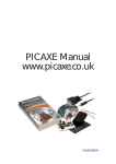
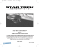
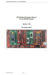
Greenpower Speed Controller GpSpeed
Development Manual
Chipping Sodbury School – Rotary Racer
V1.1 – 2015-11-21 – T.Barnaby
** Preliminary **
Table of Contents
1. Introduction............................................................................................................................................2
2. Overview................................................................................................................................................2
3. Full System Usage.................................................................................................................................4
4. Connections............................................................................................................................................6
4.1. Power Connectors P12,P13............................................................................................................6
4.2. Input Signal Connector P2.............................................................................................................7
4.3. Display Connector P1.....................................................................................................................7
4.4. Controller Connector P4.................................................................................................................7
4.5. Serial Programming Connector P5.................................................................................................8
4.6. Serial Connector P3........................................................................................................................8
4.7. PIC Programming/Debug Connector P6........................................................................................9
5. Connecting Things.................................................................................................................................9
6. Programming........................................................................................................................................11
6.1. Notes on programming.................................................................................................................12
6.2. Programming using the PicAxe environment..............................................................................12
6.3. Programming in C........................................................................................................................13
7. More Information.................................................................................................................................13
8. Copyright and Warranty.......................................................................................................................13
9. Notes....................................................................................................................................................13
1. Introduction
This document is an extension of the GpSpeed User Manual that gives a more detailed description of
the GpSpeed Greenpower motor speed controller developed for the Greenpower Cars. It describes all
of the connector pins and gives some information on developing software for the board.
The idea is to provide a platform allowing teams to get pupils involved in electronics and software
rather than provide a fully featured built end system. The basic speed controller can be extended with
software and/or other hardware modules to provide a highly featured electronics control system for a
Greenpower car. As well a speed control it offers battery voltage, current and other parameter
monitoring.
2. Overview
A basic electronic speed controller for Greenpower Electric cars. We have been using a, team built,
motor speed controller in the Rotary Racer cars for a number of years. 3 different designs have been
built and used. This is a new design that tries to bring all of our ideas together to produce a relatively
simple, pupil build-able, speed controller which is flexible enough for Greenpower teams to use and
allow for different uses as well as provide extendibility.
The idea is to provide a platform and possibly a kit allowing teams to get pupils involved in electronics
rather than provide a fully featured built end system. The basic speed controller can be extended with
software and/or other hardware modules to provide a highly featured electronics control system for a
Greenpower car. As well a speed control it offers battery voltage, current and other parameter
monitoring.
We provide an electronic schematic (circuit diagram) and PCB layout in Kicad format. This allows
modifications by teams if desired. We will, probably, also supply manufactured PCB's allowing teams
to easily build the design given here. Not all of the components are needed depending on the usage
desired. By installing extra components and changing the on-board software the design can be extended
to perform many different functions. We provide basic software that will operate the system. It is for
teams to extend this system as wanted and to get involved in the electronics and software design.
So what can it do ?
•
•
•
•
•
Can act as simple "soft start" device. Connected in line with the motor can simply provide a
motor soft start on power on while using conventional switched relay systems.
Can act as a simple "soft start" device with power switch. Using a simple on/off button will
essentially behave as a "soft start" relay.
Can act as a simple speed controller with throttle. A simple potentiometer either twist grip or
other can be used to control the speed. Power limiting can be performed with an additional
potentiometer to eek out those battery ampere/hours.
Can display information to the driver and have driver buttons (via a separate display module).
Can act as a PWM motor speed MOSFET output stage, battery voltage and current
measurement device for a higher level computer control module (no processor installed).
Some Features:
•
•
•
•
•
•
•
•
•
•
•
•
•
Uses mainly through hole components allowing easy assembly by pupils.
Relatively low cost (probably about £70 + VAT).
Uses screw terminals for the main wire connections, so easy to integrate by pupils.
Has reliable high current PWM MOSFET output stage (160 Amps) with hardware and software
current limiting. (proved over 5 years of GP racing).
Filtered, efficient and reliable 12V and 5V supply for electronics from the main 24V battery
supply. Used on board and available to external electronics.
Has a simple PIC processor that can be programmed using Picaxe Basic or 'C' to do various
tasks. Simple speed controller software and examples provided in Picaxe Basic and 'C'.
Has onboard battery voltage and hall effect motor current measuring ability. This can be used
for display to the driver or other purposes.
Has 24V PWM fan driver with filter to control variable speed motor cooling fans (or other
devices).
Three external analogue or digital inputs: One for throttle/on/off and two free for use
(temperature, car speed ?).
Has I2C bus connection for driver display panel/controls. A simple LCD or LED display
module (such as PicAxeAXE033) or own designed board to show the user voltage, current speed
etc.
Has limited memory for data logging. An I2C memory device could be connected to extend this,
but there is no real time clock (Both could be added via Control connector).
Has a serial port with power connector to allow a basic telemetry module to be attached.
Has connection to a separate car computer board for higher level control. This can be connected
to RR's existing PIC based computer, to a new ARM based data logging computer module we
are developing or to a Raspberry Pi etc. These will allow higher level control including data
logging, telemetry etc etc.
•
Can use it as a battery testing switch and datalogger to a PC. With a suitable load bank (multiple
50W bulbs) attached, the unit can perform a discharge cycle sending voltage/current info to a
PC/laptop and then switch off the load automatically when down to 11Volts.
Info on our control/data logger project is at:
http://www.greenpower.beamweb.co.uk/groups/electronics/gpControl/index.html
If you use this system all I ask is for you to involve the pupils as much as possible in the design, build,
development and usage of the systems produced. The idea is to show, educate and try to inspire young
engineers.
3. Full System Usage
This diagram shows a possible full usage scenario for the GpSpeed controller board.
LCD Display
And Switches
PWM Motor
Speed Control
Throttle Sensor
Temp Sensor
GpSpeed
Controller
PWM Fan
Speed Control
Speed Sensor
Telemetry
RTC and
Data Log
GPS
4. Connections
P12,P13: Power Connector
Reset Switch
P6: IDE Connector
P4: Controller
Connector
P3: Serial Port
P2: Input Connector
P5: Picaxe
Programming Connector
P1: Display Connector
The connections are:
4.1. Power Connectors P12,P13
These are large screw terminal connectors allowing wire of up to 16mm^2 to be connected. We
recommend the use of 10mm^2 wire. The PCB is marked with B+, B-, M+, M- and F-. Be very careful
in making sure these connections are correct !
Name Connector Pin Processor Pin
Description
F-
P12.1
Fan drive negative output. Switched PWM through LC
filter to provide a DC voltage. Connect FAN's between
this and M+.
B+
P12.2
Main battery positive input. Should be fused at 70 Amps
B-
P12.3
Main battery negative input and chassis ground.
M+
P13.1
Motor positive output. 24V DC for motor, fan and other
items. The Hall effect device will measure current taken
through this terminal.
M-
P13.2
Motor negative output. Switched PWM.
4.2. Input Signal Connector P2
This is a small screw terminal connector for control inputs. Pin 1 has a dot on the PCB.
Name Connector Pin Processor Pin
Description
I2
P2.1
RB4
General digital or analogue input. 0 – 5V.
+5V
P2.2
5V supply
Gnd
P2.3
Ground
I1
P2.4
+5V
P2.5
5V supply
Gnd
P2.6
Ground
I0
P2.7
+5V
P2.8
RA1
General analogue or digital input. 0 – 5V.
RA0
Throttle input analogue 0 - 5V
5V supply
4.3. Display Connector P1
This is an RJ12 plug in connector. Either an RJ12 telephone type of lead or a twisted pair CAT5
networking type wire can be used.
Name
Connector
Pin
I2C_INT
P1.1
Gnd
P1.2
I2C_DAT P1.3
+5V
Processor Pin
RC0
Description
Used as an I2C bus interrupt or for general digital IO
usage. Blue
Ground. Yellow
RC4
P1.4
I2C bus data or for general digital IO usage. Green
5V supply. Red
I2C_CLK P1.5
RC3
I2C bus clock or for general digital IO usage. Black
User1
RB3
General digital IO usage. White
P1.6
This presents an I2C bus that can be connected to a simple LCD display module such as the PicAxe
AXE033 or used for other purposes. If the I2C bus is not required, the lines can be used as digital IO
lines for driving LED's or switch inputs.
4.4. Controller Connector P4
This is a simple 8x2 0.1 inch header. This is used to connect to an external control and/or data logging
module using 16way IDC connector. Either a cable or a small PCB can be mounted here. Pin 1 has a
dot on the PCB.
Name
Connector Processor Pin
Pin
Description
+24V
P4.2
24V input after filtering. For battery voltage measurement
or limited power supply < 200mA.
+12V
P4.4
12V regulated power supply. Max 500mA.
+5V
P4.6
5V regulated power supply. Max 100mA.
Current1
P4.8
RA3
Hall effect current sensor output. 2.5V +- 2Volts
MotorPwm P4.10
RC2
Motor PWM input (or output if gpSpeed drives this)
FanPwm
P4.12
RC1
Fan PWM input (or output if gpSpeed drives this)
I2C_CLK
P4.14
RC3
I2C bus data or for general digital IO usage
I2C_DAT
P4.16
RC4
I2C bus clock or for general digital IO usage
Gnd
Odd pins
All odd pins are ground
With the gpSpeed processor removed or software configured not to drive the PWM signals, a remote
module can use the gpSpeed board can a simple MOSFET output stage. Alternatively the gpSpeed
processor can drive the motors and fans and take commands over the I2C bus from a remote controller.
4.5. Serial Programming Connector P5
This is a simple, PicAxe compatible, serial programming and debug connection. Requires use of a
PicAxe serial download cable with a 3.5mm jack plug.
Name
Connector Processor Pin
Pin
Description
SER2_TX P5.1
RA5
Serial TX (outside)
SER2_RX P5.2
RA4
Serial RX (middle)
Gnd
P5.3
Ground (tip)
4.6. Serial Connector P3
This is a simple set of 0.1inch spaced header pins. A simple Molex 4 pin connector could be used. This
is a simple serial connector connected to the PIC's hardware UART pins. Could be used for
programming, external serial modules or general digital IO usage. Pin 1 has a dot on the PCB.
Name
Gnd
Connector Processor Pin
Pin
P3.1
Description
Ground
SER1_RX P3.2
RC7
Serial RX
SER1_TX P3.3
RC6
Serial TX
+5V
P3.4
+5V power supply
4.7. PIC Programming/Debug Connector P6
This is a standard PIC 6 pin programming port. It can be used for development in 'C' using standard
PIC development tools. Requires a suitable PIC 6 x 0.1inch programming lead. Pin 1 has a dot on the
PCB.
Name
Connector Processor Pin
Pin
/RESET
P6.1
+5V
P6.2
+5V power supply
Gnd
P6.3
Ground
ICSPDAT
P6.4
RB7
Programmer data
ICSPCLK P6.5
RB6
Programmer clock
NC
/MCLR
Description
Microprocessor reset line
P6.6
Could be used as general digital IO if PIC programming is not needed and CPU set to allow use of the
lines.
5. Connecting Things
Most of the user inputs are fed through a simple passive signal conditioning circuit. This consists of a
simple resistor voltage divider, R1 and R2, followed by a capacitor C1 to filler the incoming signal and
remove spikes. By default, the inputs have: R1 = 4K7, R2 = 100K and C1 = 1uF. This gives a near 0 –
5V input range with a degree of low pass filtering. The battery voltage input has suitable on-board
resistors to handle a 0 to 33.6 Volt range (47k/8.2k). If it is desired to use any of these pins as outputs,
the capacitor should be removed and the value of the input resistor (R1) lowered to about 100 Ohms
giving some degree of protection to the processors I/O pin.
If lower voltage level inputs are needed an external operational amplifier circuit can be used that can
scale and offset the voltage as required. R5, R6 and R6 can be adjusted for voltage offset and gain.
The input terminal blocks have 0V and 5V connections available to allow two and three wire sensors to
be easily connected. See the Circuit Diagram for more details.
●
Voltage: Assuming the GpSpeed unit is connected to the batteries, then it can directly measure
the battery voltage without any additional wiring. The resistor dividers have, by default, a 47k
and an 8.2k resistor. So the input voltage is divided by: (47000 + 8200) / 8200 = 6.7317. The
ADC's, in 10bit mode provide values of: 0 – 1023 for a 0 to 5V input. Thus the software scaling
to provide a true voltage reading is: (6.7317 * 5) / 1023 = 0.0329. In fixed point arithmetic
scaled by 100, the scaling would be: 3.29 which could be roughly implemented as (10 * adc) / 3
in integer arithmetic.
●
Current: We have used a hall effect sensor to measure the current. The one we have used is a
HXS50, RS part number: 532-9126. This uses 5Volts and provides a voltage of 2.5V with no
current. On increasing current the voltage will decrease. It is configured with a 2 turn primary
for a 0 to 75Amp range. Thus its output voltage with respect to current will be scaled by:
0.625 / 25 = 0.025. The ADC's, in 10bit mode provide values of: 0 – 1023 for a 0 to 5V input.
First the ADC's output needs to be inverted due to the inverse current. This can be done by
subtracting the value from 512. The software scaling to provide a true current reading is: 5 /
(0.025 * 1023) = 0.1955. For fixed point arithmetic scaled by 100, the scaling would be: 19.55
which could be implemented as (119 * adc) / 6.
●
Temperature: A temperature sensor, such as a TMP37FT9Z or TMP36GT9Z, that provides an
analogue voltage can be directly connected to one of the analogue inputs. With the TMP37FT9Z
it provides a voltage of 20 mV/°C (TMP36 is 10 mV/°C). So the software scaling factor for a
TMP37 would be: 5 / (0.02 * 1023) = 0.244. This can be implemented in 100* scaled integer
arithmetic as t = 24 * adc. For a TMP36 would be: 5 / (0.01 * 1023) = 0.488. This can be
implemented in 100* scaled integer arithmetic as t = 49 * adc
●
Speed: The speed can be input from a basic reed, hall effect or optical switch driven by a
magnet on a wheel like a cycle computers sensor. A reed switch can be connected between the
input and the 5V line. The software would accurately time the period between pulses. From this
it then calculate the distance and the speed of the car.
●
Throttle: The throttle input can be a simple resistive potentiometer or a hall effect device. The
system provides a 0V and 5V connections for this. With a resistive potentiometer the ADC will
provide a value between 0 and 1023. With a Hall effect input they commonly provide a voltage
between 1 and 4V, so the range of ADC values would be in the range: 204 – 819.
●
Display and Switches: A display and switches can be connected to the RJ12 connector. This
provides +5V power, ground, an I2C serial interface and 2 I/O lines. A Picaxe AXE033 LCD
panel set to I2C mode can be used for a display. The User IO lines can be used for switches or
LED's.
●
Serial Interfaces: The SER1 and SER2 serial interfaces can be used for telemetry, GPS or
other devices.
●
Real-time clock: If a PicAxe Serial LCD module AXE033 is used, then it can be fitted with a
real-time clock chip (DS1307) to maintain a battery backed up date and time. This would be
accessible over the I2C bus. Alternatively a simple module could be made to interface with the
controllers P4 connector that can have an I2C RTC chip and perhaps some data log memory.
6. Adding a Display
The GpSpeed controller has a connector that is designed to be used to connect to a driver display. This
RJ12 type of connector provides a simple 6 wire interface. This provides 5V power, an I2C serial bus
for communications and two spare lines for other uses such as switches or LED's. It can easily be used
with the Picaxe AXE033 module:
Module: http://www.picaxe.com/Hardware/Add-on-Modules/Serial-LCD-Module/
Datasheet: http://www.picaxe.com/docs/axe033.pdf
The display can be used to display various information from the GpSpeed controller. Some examples
are:
•
Motor current. The instantaneous motor current.
•
Average motor current over a period of time, ideally the last lap.
•
Battery voltage
•
Speed
•
Motor temperature
•
Throttle position
The Picaxe AXE033 module comes as a simple kit to build. It also offers the ability to install a realtime clock chip and battery to maintain the date and time for data logging or other purposes.
When making the AXE033 module note the following:
1. The J1 link needs to be installed for I2C mode.
2. The link J1 should be left open.
3. Make sure you solder the LCD PCB to the controller PCB the right way around !
To wire the LCD module to the GpSpeed an RJ12 telephone type of lead can be used. (RS: 446-664).
The GpSpeed connector information for display connector p1 gives the pinout and the colours of the
wires in a typical RJ12 lead.
Some Notes:
1. Try and keep the cable as short as possible.
2. Run the cable away from battery and motor power cables and any others that could cause
interference.
3. Note that the displays control variable resistor may need to be adjusted in order to actually see
the display.
4. It is worth adding 2k2 pull-up resistors from the I2cClk and I2cDat lines to the 5V power line at
the display end of the cable to reduce the effects of noise.
The display can be written to using normal Picaxe AXE033 I2C commands. See the AXE033 datasheet
and the GpSpeed demo programs gpspeed-test-display.bas and gpspeed-demo-0v1.bas for more
information.
7. Programming
The following table shows the processor pins from a software perspective.
Pin
Description
B.1
LED
C.2
Motor PWM. This drives the main motor power MOSFET's via the MOSFET
driver chip.
C.1
Fan PWM. This drives the FAN MOSFET. The output of this is via an LC filter
network to provide a variable DC voltage for fan control.
A.0
Analogue Input 0, I0, throttle (0 to 5V)
A.1
Analogue Input 1, I1, misc (0 to 5V)
A.2
Analogue Input 2, Battery Voltage measurement
A.3
Analogue Input 3, Motor Current measurement (Hall effect)
B.4
Analogue/Digital Input, I2 (0 - 5V)
B.2
Analogue Input 8, Current measurement (Raw)
B.0
Error, error from Motor PWM. Pulled low on MOSFET over current
C.3
I2C Clk. I2C bus clock line for displays or other devices.
C.4
I2c DAT. I2C bus data line for displays or other devices.
C.0
User 0, I2c Int. General user line on display connector.
B.3
User 1. General user line on display connector.
C.6
SER1 TX. P3 serial port (hardware uart)
C.7
SER1 RX. P3 serial port (hardware uart)
A.5
SER2 TX. P5 serial port (software uart)
A.4
SER2 RX. P5 serial port (software uart)
Each of these pins can be configured as a digital input or digital output while some may also be used as
analogue inputs. As well as manually, in software, reading values from and driving these pins, some
can be used by on-chip hardware peripherals. The peripherals provided include:
Peripheral
Pins
Description
PWM
C.1
Hardware PWM signal generator
PWM
C.2
Hardware PWM signal generator
ADC
Analogue pins Hardware analogue to digital converter 8 or 10 bits
UART
C.6, C.7
Hardware UART for serial communications
I2C
C.3, C.4
Hardware I2C bus master or slave
It is best to use these hardware peripherals as much as possible to simplify programming.
7.1. Notes on programming
The PIC processor is essentially an 8bit microprocessor, that is, it natively works with 8bit numbers
either signed numbers in the range: -128 to 127 or unsigned numbers in the range: 0 to 255. The
software development systems provide support for 16bit numbers (-32768 to 32767 or 0 to 65535) and
indeed 32 bit numbers for 'C' by adding code to perform the appropriate mathematical operations, but
this is slower than native 8bit operations.
The PicAxe Basic environment only supports unsigned integer values in 8 bit or 16 bit forms.
The 'C' compiler can also generate the code to perform 32bit floating point calculations, but this results
in large and slow code and so is generally best avoided.
So it is generally best to work in, low bit count, integer arithmetic. To achieve a reasonable accuracy it
is useful to use fixed point arithmetic with 16bit values. For example to store 20.12 Volts you could
store and manipulate the number 2012. ie the number is scaled by 100 to effectively give two decimal
points of accuracy. When working with low bit count, integer arithmetic you have to be very careful of
over and underflows in calculations. So for each calculation you write you should consider what the
minimum and maximum values are and if necessary pre-scale them before performing the calculation.
Note that the mathematical divide operation is the most difficult for a processor to do and should be
avoided where possible. Sometimes a multiplication with fixed point numbers. Or appropriate scaling
can be performed on others. Also the processor is good at multiplying/dividing by factors of 2 such as
2,4,8 etc.
Most of our examples scale the voltage, current temperature and other readings by 100 to get two
decimal points of resolution using integer arithmetic.
7.2. Programming using the PicAxe environment
The GpSpeed board can use the PicAxe 28x2 CPU chip and then use the PicAxe Basic language like
programming environment to develop software for the GpSpeed system. The PicAxe serial download
cable must be used to download the program to the CPU on the board.
PicAxe 28x2 CPU
http://www.picaxe.com/Hardware/PICAXE-Chips/PICAXE-28X2microcontroller/
PicAxe download cable
http://www.picaxe.com/Hardware/Cables/PICAXE-USB-DownloadCable/
PicAxe development
software MS Windows
http://www.picaxe.com/Software/PICAXE/PICAXE-Editor-6/
PicAxe development
software Linux
http://www.picaxe.com/Software/PICAXE/AXEpad/
Note the Picaxe MSWindows editor will run under wine on Linux as
well.
There are some example programs on the support website at:
http://www.greenpower.beamweb.co.uk/groups/electronics/GpSpeed/index.html
7.3. Programming in C
There are a few 'C' development environments you can use. There is the Microchip MPLAB, the L:inux
pikdev and a simple Linux sdcc based system amongst others. You will need a USB ICSP download
cable (6pin) to download the programs to the board. Alternatively with an appropriate bootloader
programmed into PIC chip a PicAxe download cable can be used.
Digilent Chipkit
programmer. Low cost
programmer.
http://uk.farnell.com/digilent/chipkit-pgm/programmer-tdgl015-chipkitpgm/dp/2285430
Pickit2 USB programmer.
PIC standard programmer.
http://uk.farnell.com/microchip/pg164120/programmer-pickit-2-fullspeed/dp/9847170?Ntt=9847170
There are some example programs on the support website at:
http://www.greenpower.beamweb.co.uk/groups/electronics/GpSpeed/index.html
8. More Information
There is more information on the CSS's Electronics website at:
http://www.greenpower.beamweb.co.uk/groups/electronics
9. Copyright and Warranty
The design is copyrighted to the Chipping Sodbury Rotary Racer Greenpower team. It is provided free
for non commercial educational uses.
Note we do not provide any warranty that these systems will work or guarantee any support. The
design, information, software and any kits are supplied on an “as is” basis.
10. Notes
1. The board has a hardware current limit feature. When this triggers it switches of the output
power until a new PWM pulse arrives. If the power is set to 100% this will not happen. Easing
off the power and then bringing it back up will restart the output. If this happens the value of
resistor R18 can be reduced in value to raise the over current tripping point. Normally the
software would limit the current before this point is reached.
2. Always get an adult to check over the software and test it before using it in a Greenpower Car.
3. Make sure the software is fail safe. If the throttle is shut off the motor should be shut off no
matter what.
4. When using electronics/software to control the motor in a Greenpower car. Always have a
physical main power switch easily accessible to and known to the driver in case of problems.