1
DCOPS Interface Board
User’s manual
2. Construction
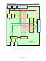
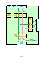
To decrease a cost all three kinds of the interface boards are realized at the same printed
circuit board with a selective assembly. There are four rectangular areas on the board
marked as:
• Install on the board # 1 only
It contains RS-422/CMOS interface with J1, J2 serial port connectors and
the TAP controller with J3 connector for download.
• Do not install on the board # 1
It contains LVDS/CMOS interface.
• Install on the board # 6 only
It contains RS-422/CMOS interface with J8 connector and TAP controller
for JTAG.
• Do not install on the board # 6
It contains two resistors only: R17 (22k ohm) pulls up RXN signal from
the non-existing next board to high level, and R18 (1.0 ohm) connects TDI
and TDO lines to provide a return path for TDO.
All other components must be assembled on all kinds of the boards.
There are eight connectors on the board (not all of them are assembled):
J1
– DAQ serial port, marked as “DAQ”,
J2
– JTAG serial port, marked as “JTAG”,
J3
– Download port for the microcontroller,
J4, J5 – Power distribution connectors,
J6
– input data exchange connector (upstream), marked as “Previous IFB”,
J7
– readout data exchange connector, marked as “Readout board”,
J8
– output data exchange connector (downstream), marked as “Next IFB”,
Page 7 of 21