1
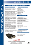
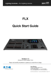
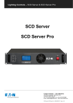
BETAPACK3 USER GUIDE
WARNING!
DO NOT REMOVE THE COVERS WITHOUT FIRST COMPLETELY DISCONNECTING
THE BETAPACK3 FROM THE MAINS SUPPLY
To Remove The Cover
Isolate and disconnect the Betapack3 from the mains supply.
The mains supply terminals (and output terminals on the hardwire version) are located under the top cover. To remove
the top cover, remove the four screws “A” in Diagram 5 from the side plates.
The Triacs (type BTA40-600A/B) are located under the bottom cover. To remove the bottom cover, remove the four
screws “B” in Diagram 5 from the side plates.
Diagram 1
Connecting The Mains
•
A separate isolator and secure mains earth connection are required.
•
Phase to Neutral voltage must not exceed 255VAC.
•
All wiring entering the Betapack3 must be rated to +85ºC, H07RN-F cable is recommended.
•
Cut outs are provided on the ends and rear for PG21 glands; one is supplied.
•
Supply terminals will accept wire sizes between 1.5mm and 16mm . Tightening torque is between 1.2Nm and
2.4Nm.
•
Hardwire Live/Neutral output terminals will accept wire sizes up to 6mm .
•
Hardwire Earth output ring-tags (blue crimp) will accept wire sizes between 1.0mm and 2.5mm . These may be
replaced if larger diameter wiring is installed.
2
2
2
2
2
Cooper Controls Ltd, Usk House, Llantarnam Park, Cwmbran, Gwent NP44 3HD, U.K
www.zero88.com
Tel: +44 (0) 1633 838088 (24hr Answer Phone)
Fax: +44 (0) 1633 867880
Email: [email protected]
73-682-00 IM8025Betapack3ManualIssue2_1.doc
Page 1 of 9
BETAPACK3 USER GUIDE
The Betapack3 is supplied configured for three-phase star operation as shown in Diagram 2:
Diagram 2
For single-phase operation, fit the supplied linking bar between the L1, L2 and L3 terminals as shown in Diagram 3:
Diagram 3
For three-phase delta operation, the 6 neutral wires must be removed from the terminal block, and the crimped ferrules
must be cut off. Strip the ends of these 6 wires, and reconnect as shown in Diagram 4:
Diagram 4
Cooper Controls Ltd, Usk House, Llantarnam Park, Cwmbran, Gwent NP44 3HD, U.K
www.zero88.com
Tel: +44 (0) 1633 838088 (24hr Answer Phone)
Fax: +44 (0) 1633 867880
Email: [email protected]
73-682-00 IM8025Betapack3ManualIssue2_1.doc
Page 2 of 9
BETAPACK3 USER GUIDE
Mounting/Installation
In a 19" Rack
The Betapack3 is supplied with side brackets fitted for rack mounting.
On a wall
Undo the four screws ‘X’ to remove the brackets, replace the screws in the holes for future use. Stand the Betapack3 on
one end. Remove the two screws ‘Y’ (see Diagram 5), fit the brackets as shown and replace screws ‘Y’. Fit the other
bracket on the other end.
The wall drilling positions are shown in Diagram 6. WARNING Completely fit one bracket at a time. Removal of all four
screws ‘Y’ at the same time can allow the heatsink assembly to fall out! Allow a minimum vertical spacing of 130mm
between packs, and between packs and other equipment. A spacing of 180mm is recommended for ease of wiring and
servicing.
For Portable Use
An ‘Easicarry’ Option Kit consisting of a handle and four feet is available (Stock No: 00-540-00). Contact your dealer for
further details. To fit, remove the brackets. Fit the handle using the screws supplied and holes ‘Z’. Fit the four feet to the
other end using the holes ‘X’ and ‘Y’. See Diagram 5.
Diagram 5
Diagram 6
Ventilation
The Betapack3 is convection cooled with air flowing over the rear mounted heatsink.
When one or more Betapack3s are mounted in an enclosed rack, a fan MUST be fitted to ensure that adequate cool air
is circulated. Up to three Betapack3s may be stacked in free air.
Cooper Controls Ltd, Usk House, Llantarnam Park, Cwmbran, Gwent NP44 3HD, U.K
www.zero88.com
Tel: +44 (0) 1633 838088 (24hr Answer Phone)
Fax: +44 (0) 1633 867880
Email: [email protected]
73-682-00 IM8025Betapack3ManualIssue2_1.doc
Page 3 of 9
BETAPACK3 USER GUIDE
Specification Overview
Mode Button
The Betapack3 is a well specified versatile dimmer,
offering six channels each capable of driving up to
10Amp loads.
The Mode button is used to cycle through the different
set-up modes. They are;
The Betapack3 features breakers as standard, preheat,
topset and 3 laws per channel, 12 memories, 3 99-step
sequences, local control and DMX patch per channel.
An isolated DMX512-A input and loop-through allow for
remote operation. When the loop-through plug is not
inserted, the DMX line is automatically terminated.
The DMX control port supports RDM (Remote Device
Management) functionality (version 02.00 firmware
onwards).
- Manual control
- DMX address
- DMX fail
- Memory
- Sequence
- Preheat
- Topset
- Law
Enter Button
The Enter button is used to confirm actions.
Up & Down Buttons
Control Interface
The main display consists of four seven-segment
displays; the data displayed is dependent on the set-up
mode of the Betapack3. Around the outside of these
displays are eight red LEDs which indicate the current
set-up mode of the Betapack3. An additional green LED
is used for DMX indication.
The Betapack3 has a default mode, for operation. In
this mode non of the set-up mode LEDs will be lit, and
the main display will show the DMX address(es).
These are used to adjust the values shown in the main
display. Pressing both buttons together will reset the
display to the default values.
Default Mode
If a block patch has been set (see ‘DMX Address’
below), then the display will show the DMX start
address of the block.
If individual DMX addresses have been set for each
channel, then the ‘Up & Down’ Arrows can be used to
select which DMX address to display, or alternatively if
‘Auto’ is selected, then the display will cycle through all
six DMX addresses. In either case, the DMX address is
prefixed by the channel number.
Holding down the ‘Enter’ button in default mode will
change the display to ‘Out’, and the top 6 setup LEDs
(numbered) will change to displaying an indication of
the current output levels. Each LED will be lit if the
current output level for that channel is greater than
20%.
Channel Test - While keeping the ‘Enter’ button held
down in Default Mode, use the ‘Up & Down’ Arrows to
set a level of 100% on a single channel. Release the
‘Enter’ button to remove this level.
Cooper Controls Ltd, Usk House, Llantarnam Park, Cwmbran, Gwent NP44 3HD, U.K
www.zero88.com
Tel: +44 (0) 1633 838088 (24hr Answer Phone)
Fax: +44 (0) 1633 867880
Email: [email protected]
73-682-00 IM8025Betapack3ManualIssue2_1.doc
Page 4 of 9
BETAPACK3 USER GUIDE
Set-up Modes
Memories
Manual Control
The Betapack3 will store 12 memories for stand alone
operation, these can only be re-called if there is no
DMX present.
The Manual Control Mode allows you to set-up a look
on the Betapack3 without using an external controller.
Select ‘Manual’ mode using the ‘Mode’ button. The
display will show C.LLL, where C is the channel number
and LLL is the level. Select the channel you require or
‘A’ for all channels, using the ‘Up & Down’ Arrows and
press ‘Enter’. Now set the level you require using the
‘Up & Down’ Arrows and press ‘Enter’ again to confirm
and move back to the channel selection.
The Manual Control levels are reset to zero if power to
the Betapack3 is lost.
1. Set-up the scene using the ‘Manual’ control
function or a DMX controller.
2. Select ‘Memory’ using the ‘Mode’ button.
Using the ‘Up & Down’ Arrows select the required
memory number and press the ‘Enter’ button to confirm.
A ‘p’ should appear next to the memory to signify that it
has been programmed.
Holding both the ‘Up & Down’ Arrows for 1 second will
clear the selected memory. If these buttons are held for
5 seconds, ALL memories will be cleared.
DMX Address
There are 2 ways that the Betapack3 can be patched –
a single DMX start address can be set for the block of 6
channels (block patch), or each channel can be given a
different DMX start address.
If memories are cleared which are used in sequences,
they will be removed automatically from those
sequences.
Sequences
For block patch, the range of DMX start addresses is
001 – 507. For individual patch, the range of DMX start
addresses is 001 – 512
Select ‘DMX ADR’ using the ‘Mode’ button, the display
will show C.AAA, where C is the channel number and
AAA is the current DMX address for that channel.
Select the channel you require (1-6), or ‘A’ for all
channels (block patch), using the ‘Up & Down’ Arrows
and press ‘Enter’. Now set the address you require
using the ‘Up & Down’ Arrows and press ‘Enter’ again
to confirm and move back to the channel selection.
The Betapack3 will store 3 sequences of up to 99-steps
each. Each step is a link to one of the 12 programmed
memories. Sequences can only be replayed if there is
no DMX present.
Each sequence can have a fade time (0-60s) and dwell
time (1-60s) programmed. It is only possible to add
steps to or remove steps from the end of a sequence.
1. Program the required looks using the ‘Memories’
function (see above).
2. Select ‘Sequence’ using the ‘Mode’ button.
DMX Fail
There are four DMX fail modes available – ‘hold DMX’,
‘fade to black’, ‘fade to memory’ and ‘fade to sequence’.
Select ‘DMX Fail’ using the ‘Mode’ button. Using the
‘Up & Down’ Arrows select your preferred choice from
the list below;
Fail Mode
Hold Last State
Main Display
Hold
Fade to Memory 1 - 12
F 00
F 01 – F 12
Fade to Sequence 1 - 3
S 01 – S 03
Fade to Zero
If there is no DMX present, the selected
memory/sequence will be re-called immediately.
3. Use the ‘Up & Down’ Arrows to select the required
sequence (the number of steps already
programmed in each sequence is shown after the
sequence number on the display), and press the
‘Enter’ button to confirm.
4. The display will now change to show the current
step number, followed by the memory currently
programmed in that step. Use the ‘Up & Down’
Arrows to select the required step number (or Fade
time ‘F’ or dwell time ‘d’), and press the ‘Enter’
button to confirm.
5.
For steps:
If there is no DMX present, the selected memory
will be immediately re-called. Use the ‘Up & Down’
Arrows to select the memory for that step, and
press the ‘Enter’ button to confirm. Only
programmed memories may be selected. If the
step is at the end of the sequence, then the step
number will automatically increment and further
steps may now be programmed in the same way.
Otherwise the display will return to step number
selection mode.
Cooper Controls Ltd, Usk House, Llantarnam Park, Cwmbran, Gwent NP44 3HD, U.K
www.zero88.com
Tel: +44 (0) 1633 838088 (24hr Answer Phone)
Fax: +44 (0) 1633 867880
Email: [email protected]
73-682-00 IM8025Betapack3ManualIssue2_1.doc
Page 5 of 9
BETAPACK3 USER GUIDE
Dimmer Laws
For fade and dwell times:
If there is no DMX present, the sequence will now
run. Use the ‘Up & Down’ Arrows to change the
time, and press the ‘Enter’ button to confirm.
When done, or to return to sequence selection mode
(step 3 above) at any point, press and hold the ‘Enter’
button for 1s.
At step 3 above, holding both the ‘Up & Down’ Arrows
for 1 second will clear the selected sequence. If these
buttons are held for 5 seconds, ALL sequences will be
cleared.
At step 5 above, if the selected step is at the end of the
sequence, holding both the ‘Up & Down’ Arrows will
clear the selected step.
Preheat
Three dimmer laws are available, which can be
selected per channel.
Select ‘Law’ mode using the ‘Mode’ button. Using the
‘Up & Down’ Arrows select the channel required, or ‘A’
for all channels. Press ‘Enter’ to confirm. Now select
the law you require, again using the ‘Up & Down’
Arrows and press ‘Enter’ to confirm and return to the
channel selection.
Output Law
Normal
Switch
Linear
Main Display
n
S
L
Note that if the law is set to Switch, the switchpoint can
be set in the ‘Topset’ menu.
Preheat can be selected on a per channel or all channel
basis. The preheat level is 5% and cannot be adjusted.
Select ‘Preheat’ by cycling through the modes using
the ‘Mode’ button.
Select required channel or ‘A’ for all channels, using the
‘Up & Down’ Arrows and press ‘Enter’, to confirm.
Now select on/off using the ‘Up & Down’ Arrows. Press
‘Enter’ to confirm and return to the channel selection.
Note that Preheat is only applied if there is a DMX input
present, and the law is not set to ‘Switch’.
Topset
Topset can be selected on a per channel or all channel
basis. On the Betapack3, Topset is applied as a limiting
(not scaling) value.
Select ‘Topset’ by cycling through the modes using the
‘Mode’ button.
Select required channel or ‘A’ for all channels, using the
‘Up & Down’ Arrows and press ‘Enter’, to confirm.
Now select the topset level you require, again using the
‘Up & Down’ Arrows and press ‘Enter’ to confirm and
return to the channel selection.
Note that if the law is set to ‘Switch’, the setting in
Topset will instead be used to determine the
switchpoint. The ‘Topset’ LED will flash in this case, to
indicate the setting being made.
Cooper Controls Ltd, Usk House, Llantarnam Park, Cwmbran, Gwent NP44 3HD, U.K
www.zero88.com
Tel: +44 (0) 1633 838088 (24hr Answer Phone)
Fax: +44 (0) 1633 867880
Email: [email protected]
73-682-00 IM8025Betapack3ManualIssue2_1.doc
Page 6 of 9
BETAPACK3 USER GUIDE
Super User
Internal Temperature
The Betapack3 has a number of hidden functions,
located in the Super User Menu. The super user
menus can only be accessed from the Default mode
(no LEDs lit). To enter Super User press and hold the
‘Up & Down’ Arrows together and press and hold the
‘Mode’ button for 5 seconds. All the mode LEDs will
flash to indicate the Betapack3 is in super user mode.
Press the ‘Up & Down’ Arrows until the temperature is
shown in the display, shown as xxxC, where xxx is the
temperature in Centigrade. The ‘Enter’ button has no
function in this mode.
The ‘Up & Down’ Arrows are used to cycle through the
various super user functions. Pressing the ‘Mode’
button at any point will revert to normal operation. If no
buttons are pressed after 20 seconds the unit will
automatically revert to normal operation.
To enable or disable RDM (Remote Device
Management) functionality on the DMX control port,
press the ‘Up & Down’ Arrows until “ron” or “rof” is
displayed. The ‘Enter’ button toggles this setting
between “ron” (RDM enable) and ”rof” (RDM
disabled).
RDM Enable/Disable
Dimmer Lock/Unlock
Press the ‘Up & Down’ Arrows until the display shows
“LOC”. Press ‘Enter’ to confirm this action. The
Betapack3 will revert to the Default mode. Pressing the
‘Mode’ button now will only cycle between Manual
Control and Default Mode.
If Super User is entered when the Betapack3 is locked,
only the unlock function will be available. The display
will show “UNL”. To unlock the Betapack3, press and
hold the ‘Enter’ button for 5 seconds. The Betapack3
will unlock and exit super user returning to the Default
mode.
Resetting The Betapack3
Press the ‘Up & Down’ Arrows until the display shows
“rset”. Press ‘Enter’ to confirm. The display will flash
briefly to confirm this action. The Betapack3 will be
reset to its default settings, shown in the table below:
Set Up Parameter
Manual Control Levels
DMX Addresses
DMX Fail Mode
Memory
Sequence
Preheat
Topset
Law
Switch law switchpoint
RDM
State
All Off
Block patch at 001
Hold Last State
All Memories Cleared
All Sequences Cleared
Off (0%) for all channels
100% for all channels
Normal law for all channels
50% for all channels
Enabled
Firmware Version
To identify which version of firmware is loaded in the
Betapack3, press the ‘Up & Down’ Arrows until the
firmware version is shown in the display (e.g. 02.00)
Press and hold the ‘Enter’ button for 1s, and the
Betapack3’s CPU serial number will be displayed.
Press the ‘Enter’ button again to return to the version
display. Note that the firmware version will also be
shown briefly on start up.
Cooper Controls Ltd, Usk House, Llantarnam Park, Cwmbran, Gwent NP44 3HD, U.K
www.zero88.com
Tel: +44 (0) 1633 838088 (24hr Answer Phone)
Fax: +44 (0) 1633 867880
Email: [email protected]
73-682-00 IM8025Betapack3ManualIssue2_1.doc
Page 7 of 9
BETAPACK3 USER GUIDE
Technical
DMX Indication
WARNING
DO NOT REMOVE THE COVERS WITHOUT
FIRST COMPLETELY DISCONNECTING THE
BETAPACK3 FROM THE MAINS SUPPLY
On
Flash
Fast
Flash
Slow
Off
Electrical
The Betapack3 is designed to operate on 230VAC
+10% -15% at 50-60Hz (auto sensing). The pack may
not operate satisfactorily outside this specification.
The packs may be wired:
• Single Phase: 60A 1 phase 2-wire 230V
(255V max phase to neutral)
Earth leakage less than 1mA
• Three Phase Star: 20A 4-wire 230/380V
(255V max phase to neutral)
Earth leakage less than 1mA
• Three Phase Delta: 30A 3-wire 230V
(255V max phase to phase)
Earth leakage less than 4mA
- Max total load: 13.9kW @ 230V
- Load per channel: 0.1A Min; 10A Max
- No load consumption: 10W
- Rise Time: 80uS
- Triac Type: BTA40-600A/B
If used in conjunction with MCBs, to avoid nuisance
tripping use high inrush current (Type K) MCBs.
Lighting loads may be resistive or inductive and include
tungsten, transformer driven low voltage (e.g. pinspots),
and quartz halogen. Electronic transformers must be
suitable for leading edge dimming.
Portable Appliance Testing
WARNING The Betapack3 will fail the portable
appliance high voltage test as it has capacitors
connected between Live 1/2/3 and Earth, and between
Neutral and Earth, to enable it to comply with CE
regulations.
DMX Connections
DMX dimmer data (start byte of
00) being received OK.
DMX data being received, but not
dimmer data (start byte of 00)
DMX data errors occurring.
No DMX data being received.
RDM Support:
Protocol
Version
Device
Model ID
Pin 1
Pin 2
Pin 3
Pin 4
Pin 5
0V
DMX- (RS485 B line)
DMX+ (RS485 A line)
Reserved
Reserved
307 (0x0133)
Supported
Parameters
DMX_START_ADDRESS,
SENSOR_DEFINITION,
SENSOR_VALUE,
DEVICE_LABEL,
MANUFACTURER_LABEL,
DEVICE_MODEL_DESCRIPTION
Sub Devices
6 (one per channel)
Mechanical
- Height: 175mm
- Width: 440mm
- Depth: 195mm
- Weight: 8.0kg (17.6lb)
Cooling
Ambient Temperature: +5ºC to +40ºC.
Relative Humidity: 5% to 95% non-condensing.
The Betapack3 is convection cooled, and includes a
temperature sensor which monitors the internal
temperature. If the temperature rises above the normal
operating level the outputs are first reduced, then
switched off altogether until the temperature falls back
to a safe level.
The table below shows how the Betapack3 will react
under these conditions. (Note: The temperature shown
on the display will be the actual temperature not the
rounded figures given below)
Temperature
Output Levels
(% of control)
Main
display
<75ºC
100%
normal
75ºC→80ºC
100%
“075c”
80ºC→85ºC
80%
“080c”
85ºC→90ºC
60%
“085c”
90ºC→95ºC
40%
“090c”
>95ºC
0%
“hot”
sensor fault
100%
“err”
Conforms to USITT DMX512-A (isolated).
One male and one female 5 pin XLR connector. DMX
line is automatically terminated when the loop-through
plug is not inserted. The pin assignment is:
1.0
Cooper Controls Ltd, Usk House, Llantarnam Park, Cwmbran, Gwent NP44 3HD, U.K
www.zero88.com
Tel: +44 (0) 1633 838088 (24hr Answer Phone)
Fax: +44 (0) 1633 867880
Email: [email protected]
73-682-00 IM8025Betapack3ManualIssue2_1.doc
Page 8 of 9
BETAPACK3 USER GUIDE
Trouble Shooting Guide
Below is a list of common issues experienced by Betapack3 users.
If you are experiencing problems with your dimmer, please check the list below for common causes and solutions.
WARNING : These checks should ONLY be carried out by a qualified electrician.
If you are unsure how to make any of the checks please contact Cooper Controls technical support for advice or
assistance.
Symptoms
Solutions
•
Check there is a mains voltage on the incoming supply terminal.
•
Check the incoming supply terminals are all adequately tightened.
•
Check the link cable between the control PCB on the front panel
and the power PCB has not been disconnected or damaged.
•
Check the channel breakers are in the ‘on’ position.
•
Check the channels have not had a Topset applied to them. Please
see Page 6 Topset for further details.
•
If dimmer is wired single phase check that the single phase link bar
has been fitted. If it is fitted check the screws are adequately
tightened. Please see Page 2 diagram 3 for further details.
•
The channel law has been set to switch. Please see Page 6
Dimmer Laws for further information.
The display is outputting a
sequence of numbers
after the dimmer has been
powered up.
•
•
Channels have been soft patched.
Please see page 4 & 5 DMX Address for further details.
Unable to access any of
the dimmer functions.
•
•
Dimmer has been locked.
Please see Page 6 Dimmer Lock/Unlock for further details.
Channel is remaining on
all the time, even after
disconnecting the
controller and power
cycling the dimmer.
•
Triac has failed. Please contact your local service centre or contact
Cooper Controls technical support for further information
Dimmer does not power
up when power is applied.
Dimmer is powering up
but some or all of the
channels are either not
working or will not go to
full output.
Channels will switch on
and off but are not able to
be dimmed.
Notes:
Cooper Controls Ltd reserves the right to make changes to the equipment described in this manual without prior notice.
This equipment is designed for professional stage lighting control, and is unsuitable for any other purpose. It should be used by, or
under the supervision of, an appropriately qualified or trained person.
E&OE. Cooper Controls Ltd reserves the right to change the specification without prior notice.
Manual Stock Number: 73-682-00 Issue 2.1: August 2009
© Cooper Controls Ltd 2006-2009
Cooper Controls Ltd, Usk House, Llantarnam Park, Cwmbran, Gwent NP44 3HD, U.K
www.zero88.com
Tel: +44 (0) 1633 838088 (24hr Answer Phone)
Fax: +44 (0) 1633 867880
Email: [email protected]
73-682-00 IM8025Betapack3ManualIssue2_1.doc
Page 9 of 9