1
Model HI-6113
Laser Data Interface
and Probe Measurement System
User Manual
ETS-Lindgren Inc. reserves the right to make changes to any product described
herein in order to improve function, design, or for any other reason. Nothing
contained herein shall constitute ETS-Lindgren Inc. assuming any liability
whatsoever arising out of the application or use of any product or circuit
described herein. ETS-Lindgren Inc. does not convey any license under its
patent rights or the rights of others.
© Copyright 2005–2012 by ETS-Lindgren Inc. All Rights Reserved. No part
of this document may be copied by any means without written permission
from ETS-Lindgren Inc.
Trademarks used in this document: The ETS-Lindgren logo and ProbeView are
trademarks of ETS-Lindgren Inc.; Microsoft, Windows, and Windows Vista are
registered trademarks of Microsoft Corporation in the United States and/or other
countries; Intel and Pentium are registered trademarks of Intel Corporation.
ii
|
Revision Record | MANUAL, HI-6113 | Part #H-600098, Rev. H
Revision
Description
Date
A
Initial Release
June, 2005
B
Edits to all sections for updated
HI-6113 design; Field Probe content
moved to EMC Field Probes User
Manual; reorganized content, updated
format
October, 2006
C
Added Appendix B: EC Declaration of
Conformity; Updated descriptions of I
and r commands in Appendix A:
Operating Protocols
December, 2006
D
Updated ProbeView™ Laser
information
November, 2007
E
Updated download information;
rebrand
September, 2008
F
Added Notes, Cautions, and
Warnings; added General Safety
Considerations
March, 2011
G
Updated USB driver installation
information
October, 2011
H
Updated LASER HOT description in
HI-6113 Indicators.
November, 2012
|
iii
Table of Contents
Notes, Cautions, and Warnings .............................................. vii
General Safety Considerations ............................................. viii
1.0 Introduction .......................................................................... 9
System Description ..................................................................................... 9
Minimum Computer Requirements ............................................................ 10
ETS-Lindgren Product Information Bulletin ............................................... 11
2.0 Maintenance ....................................................................... 13
Laser Probes and Maintenance of Fiber Optics......................................... 13
Replacement and Optional Parts .............................................................. 14
Service Procedures .................................................................................. 15
3.0 Quick Start to Operation ................................................... 17
Download and Install the Software ............................................................ 17
Connect the Hardware .............................................................................. 17
Run a Warm Up Period ............................................................................. 18
Run the System ........................................................................................ 19
Field Probe Operating Protocols ............................................................... 19
4.0 HI-6113 Indicators .............................................................. 21
5.0 ProbeView Laser Software ................................................ 23
Download and Install ProbeView Laser ..................................................... 23
Start ProbeView Laser .............................................................................. 24
ProbeView Laser Main Screen .................................................................. 25
ProbeView Laser Menus ........................................................................... 25
File Menu .......................................................................................... 26
View Menu ........................................................................................ 27
Probe Menu ...................................................................................... 29
Communications Menu ..................................................................... 31
Help Menu ........................................................................................ 32
Probe Interaction Screen .......................................................................... 32
Communication Status .............................................................................. 33
Field Intensity.................................................................................... 33
Units ................................................................................................. 34
iv
|
Temperature ..................................................................................... 34
Probe Information ............................................................................. 34
Peak ................................................................................................. 34
Bar Graph ......................................................................................... 34
Using Excel with ProbeView Laser............................................................ 35
Options Window........................................................................................ 35
Moving Average ................................................................................ 36
Text update rate ................................................................................ 36
Annotating Logged Data ................................................................... 36
Colors ............................................................................................... 37
Human Exposure ...................................................................................... 38
Miscellaneous ........................................................................................... 38
Sample Limit ..................................................................................... 38
Auto Update Interval ......................................................................... 38
Sample Rate ..................................................................................... 39
Zoom-In / Zoom-Out ......................................................................... 39
Human Exposure (Health and Safety) ............................................... 39
Appendix A: Warranty ............................................................. 41
Appendix B: Operating Protocols .......................................... 43
Communication Protocol ........................................................................... 43
Information Transfer Protocol .................................................................... 43
Command Structure .......................................................................... 43
Commands ....................................................................................... 44
HI-6113 Laser Data Interface Commands ......................................... 46
Error Codes .............................................................................................. 47
Appendix C: EC Declaration of Conformity .......................... 49
|
v
This page intentionally left blank.
vi
|
Notes, Cautions, and Warnings
Note: Denotes helpful information intended to
provide tips for better use of the product.
Caution: Denotes a hazard. Failure to follow
instructions could result in minor personal injury
and/or property damage. Included text gives proper
procedures.
Warning: Denotes a hazard. Failure to follow
instructions could result in SEVERE personal injury
and/or property damage. Included text gives proper
procedures.
See the ETS-Lindgren Product Information Bulletin for safety,
regulatory, and other product marking information.
|
vii
General Safety Considerations
LASER HAZARD. Laser power up to 150 mW at
830 nm may be accessible at the fiber connector of the
laser. However, the laser beam itself is not hazardous
as the interlock ensures that the exposure time will be
less than 30 ms.
See the ETS-Lindgren Product Information Bulletin for safety,
regulatory, and other product marking information.
viii |
1.0 Introduction
System Description
The ETS-Lindgren HI-6113 Laser Data Interface and Field Probe
Measurement System consists of:
HI-61XX Series Field Probe
HI-6113 Laser Data Interface
Universal input DC power supply
Fiber optic cables
ProbeView Laser software download—To download
ProbeView Laser, see page 23
See Minimum Computer Requirements on page 10 for the computer
specifications required to install and operate the HI-6113.
The HI-61XX Series Field Probe contains a photo-voltaic converter that provides
power to the probe circuitry when sufficient light power is received by the
converter. The light power is generated by a laser in the HI-6113, and is
transmitted to the converter through an optical fiber cable assembly. This duplex
fiber cable is also used for communication between the Field Probe and the
HI-6113.
Introduction
|
9
The HI-6113 is an automated laser controller that accepts commands from the
software running on the computer and then returns the requested data. Upon
receiving the command to turn on the system, the HI-6113 initiates a startup
sequence that turns on the laser, which provides power to the Field Probe. The
Field Probe, when powered up and running, continuously sends data to the
HI-6113. The HI-6113 returns data to the computer software upon request in
either unprocessed raw form or processed form, depending on the requested
data format. The USB interface provides the data communication between the
computer software and the HI-6113.
The Field Probe system incorporates a safety interlock mechanism that turns off
the laser if the HI-6113 does not receive data from the probe within a specified
time frame. The safety mechanism is intended to prevent injury from the laser if
the HI-6113 issues a command to turn on the laser while the fiber optic cables
are disconnected, improperly connected, cut, or damaged.
The universal input power supply provides 5 volts DC power to the HI-6113.
Minimum Computer Requirements
To install ProbeView Laser and operate the Field Probe and HI-6113, you must
have an Intel® Pentium® III computer with one USB port, installed with one of
the Microsoft® Windows® operating systems; see page 18 for a list of supported
operating systems. An externally powered USB hub may be required for
computers without a USB port.
Due to the graphics in ProbeView Laser, a 300 MHz processor or
better is desirable. A slower machine will run ProbeView Laser, but
the sample rates will be slower. Toggling off the bar and scatter
graphs may increase sample rate performance.
10
|
Introduction
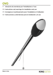
Sample Setup (computer not included)
ETS-Lindgren Product Information Bulletin
See the ETS-Lindgren Product Information Bulletin included with your shipment
for the following:
Warranty information
Safety, regulatory, and other product marking information
Steps to receive your shipment
Steps to return a component for service
ETS-Lindgren calibration service
ETS-Lindgren contact information
Introduction
|
11
This page intentionally left blank.
12
|
Introduction
2.0 Maintenance
Before performing any maintenance,
follow the safety information in the
ETS-Lindgren Product Information
Bulletin included with your shipment.
WARRANTY
Maintenance of the HI-6113 is limited to
external components such as cables or
connectors.
If you have any questions concerning
maintenance, contact ETS-Lindgren
Customer Service.
Laser Probes and Maintenance of Fiber Optics
The fiber optic connectors and cables used with laser-powered probes can be
damaged from airborne particles, humidity and moisture, oils from the human
body, and debris from the connectors they plug into. Always handle connectors
and cables with care, using the following guidelines.
Maintenance
|
13
Before performing any maintenance, disconnect
the fiber optic cables from the unit and turn off
power.
When disconnecting fiber optic cables, apply the
included dust caps to the ends to maintain their
integrity.
Before connecting fiber optic cables, clean the
connector tips and in-line connectors.
Before attaching in-line connectors, clean them
with moisture-free compressed air.
Failure to perform these tasks may result in
damage to the fiber optic connectors or cables.
Replacement and Optional Parts
Following are the part numbers for ordering replacement or optional parts for the
HI-61XX Series Field Probe.
14
Part Description
Part Number
Laser Data Interface Probe Kit
Manual
H-600098
Cable Assembly, Fiber, FC-FC,
ST-ST
H-491263-xx
ST to ST Inline Connector
708027
FC to FC Inline Connector
H-23861521000
Tripod, Dielectric, Field Probe
H-491009
Probe Stand
H-491269
|
(xx = length in meters)
Maintenance
Service Procedures
For the steps to return a system or system component to ETS-Lindgren for
service, see the Product Information Bulletin included with your shipment.
Maintenance
|
15
This page intentionally left blank.
16
|
Maintenance
3.0 Quick Start to Operation
Before connecting any components, follow the
safety information in the ETS-Lindgren
Product Information Bulletin included with your
shipment.
Download and Install the Software
Download ProbeView Laser software from www.ets-lindgren.com, and then
install it on the host computer. For download and installation steps, see
ProbeView Laser Software on page 23.
Connect the Hardware
1.
Remove the protective caps from the fiber optic cables for the
HI-61XX Series Field Probe and clean the connectors with the
provided cleaning kit.
When disconnecting and connecting the fiber cables, always clean the
ends prior to re-connecting.
2.
Remove the protective caps from the HI-6113 Laser Data Interface and
use compressed air to dislodge any obstruction within the connectors.
3.
Connect the fiber optic cables by matching ST to ST and FC to FC.
Both connectors are keyed.
4.
Connect the standard end of the USB cable to an available USB port
on the host computer.
5.
Connect the mini-USB end of cable to the HI-6113.
6.
Connect the DC power supply to the HI-6113. The power LED on the
HI-6113 should indicate green, and Microsoft® Windows® will
recognize and acknowledge the HI-6113.
Quick Start to Operation
|
17
7.
The USB driver for the HI-6113 automatically downloads and installs
when the HI-6113 is plugged into a computer that is connected to the
Internet and that is installed with one of the following supported
Microsoft Windows operating systems:
Windows XP operating system
Windows Vista® Client operating system
Windows Vista Client x64 operating system
Windows 7 Client operating system
Windows 7 Client x64 operating system
If you use an operating system not listed, please contact
ETS-Lindgren.
If your computer is not connected to the Internet, or it is connected but
the automatic installation failed or was cancelled, you will need to
download the drivers from www.ets-lindgren.com and manually install
them on your computer.
Go to www.ets-lindgren.com.
On the Resources menu, click Software/Firmware.
In the Software column, click USB Virtual Comm Port Driver
(the name of the zip file may vary slightly). Save the zip file to the
desired location on your computer.
Extract the files from the downloaded zip file.
In the same section on the ETS-Lindgren website where the driver is
located, click the link to download the installation instructions. Follow
those instructions to install the USB driver on your computer.
Run a Warm Up Period
Prior to starting a test, allow time for the Field Probe to warm up. Depending on
the ambient temperature, 5 to 10 minutes of run time are required for a sufficient
warm up period.
18
|
Quick Start to Operation
Run the System
For information on starting and using ProbeView Laser, see Running
ProbeView Laser on page 24.
Field Probe Operating Protocols
For information on operating protocols, including command structure, commands,
and error codes, see Appendix A: Operating Protocols on page 43.
Quick Start to Operation
|
19
This page intentionally left blank.
20
|
Quick Start to Operation
4.0 HI-6113 Indicators
Use of controls or adjustments, or performance
of procedures other than those specified may
result in hazardous radiation exposure.
Before connecting any components, follow the
safety information in the ETS-Lindgren
Product Information Bulletin included with your
shipment.
For complete information on the HI-61XX Series Field Probe, see the
separate Field Probe manual.
HI-6113 Indicators
|
21
The HI-6113 Laser Data Interface contains the laser for powering the
Field Probe, and also handles the communication between the probe and the
host computer.
The first two LEDs on the front of the device indicate the status of the laser:
22
LASER HOT (red)
-
Constant On—This is a warning that the laser is running too hot
and the system should be checked. Dirty fiber ends, poor inline
connections, or damaged fiber cables are among the causes of a
LASER HOT warning. The system should be shut down as soon
as possible, and the cause of the additional heat investigated.
Continuing to run in a LASER HOT state will reduce the life of the
HI-6113.
-
Flash—This is an indication that the laser current is approaching
0.8 mA. During the initialization phase of the startup process the
HI-6113 provides the probe with more light and then rolls back the
power to a normal level. In these instances the user may see
LASER HOT flash on; this is normal operation.
LASER OK (blue)—This is the normal status when probe
communication is established and the HI-6113 is providing laser light
to the Field Probe for power.
RECEIVE (amber) and TRANSMIT (white)—These are illuminated
during normal use. RECEIVE indicates the communication between
the Field Probe and the HI-6113, and TRANSMIT indicates the
communication between the host computer and the HI-6113.
POWER (Green)—This indicates that the HI-6113 is using power from
the DC power supply. This should be lit as soon as the HI-6113 is
connected to the power supply.
|
HI-6113 Indicators
5.0 ProbeView Laser Software
The ProbeView Laser software provides real-time display, logging, and
analysis of Field Probe data. It displays a variety of test information, both
numerically and graphically.
Download and Install ProbeView Laser
See Minimum Computer Requirements on page 10 for the computer
specifications required to install and operate the Laser Data Interface
and Field Probe Measurement System.
1.
Go to www.ets-lindgren.com.
2.
On the Resources menu, click Software/Firmware.
3.
In the Software column, click ProbeView Laser.
4.
Save the ProbeView Laser zip file to the desired location.
5.
Navigate to the location of the saved ProbeView Laser zip file, and
click to open.
6.
Click setup.exe. ProbeView Laser installs in
C:\Program Files\ProbeView.
The first time the HI-6113 is used with the host computer, you may
need to download and install the USB driver. For more information,
see Connect the Hardware on page 17.
ProbeView Laser Software
|
23
Start ProbeView Laser
1.
Start ProbeView Laser. Click Start, All Programs, ProbeView, and
then click ProbeView Laser.
2.
Verify the communications port. Connecting the HI-6113 Laser Data
Interface to a USB port automatically assigns the communication port
number. To change which communication port is assigned to the
HI-6113:
Plug the HI-6113 into a USB port on the computer.
Open the Device Manager.
Click Ports (COM & LPT).
Click the name of the USB device.
Click the Port Settings tab.
Click Advanced.
Click COM Port Number and select the desired COM port.
Click OK, and then click OK.
If the communications port is not set up, the software will indicate the
default port is not correct. See Communications Menu on page 31 for
information on selecting the correct port.
3.
Receive information from the Field Probe. Click the start button
located on the right side of the menu bar. Some of the LEDs on the
HI-6113 flash as information transfers to the HI-6113. When complete,
a message will indicate that the Field Probe is connected, and field
readings will display.
Select the bar graph icon on the menu to change the peak graph to the
manual commands menu. The area is used to control the HI-6113, and
includes additional commands and system information.
4.
24
ProbeView Laser will continue to look for a Field Probe until one is
detected. Automatic testing will be done to determine the type of Field
Probe that is attached. If the HI-6113 is connected to the selected
communication port, the LEDs on the HI-6113 will flash.
|
ProbeView Laser Software
ProbeView Laser Main Screen
The main screen displays the field strength or power density readings of the
Field Probe. The data is displayed as numeric values and graphs.
ProbeView Laser Menus
ProbeView Laser commands are organized into a series of menus: File, View,
Probe, Communications, and Help. The following example screens assume a
Field Probe is active and collecting data.
ProbeView Laser Software
|
25
FILE MENU
26
File Menu
Description
Open
Select and open a file that was previously logged
and saved by ProbeView Laser.
Save As
Saves logged data to a file. ProbeView Laser, by
default, will assign csv as the file type. This is a
comma-separated values file that may be
opened in several data analysis programs,
including Excel.
Exit
Exit ProbeView Laser.
|
ProbeView Laser Software
VIEW MENU
View Menu
Description
Moving Average
(Human Exposure)
Monitors the human exposure to EMF.
Readings are sampled at one per second, and
divided by the number of samples in the selected
moving average period. When the moving
average is started or reset, all the samples begin
at zero. For every second during the first period
of the selected moving average period, one of
the zeros is replaced with a reading. At the end
of the first period of the selected moving average
period, the oldest reading is replaced with a new
reading. This continues until the moving average
is reset, which begins a new moving average.
ProbeView Laser Software
|
27
28
View Menu
Description
Bar Graph
Displays the field intensity or power density for
each axis and the combined field intensity of the
X, Y, and Z axes.
Scatter Graph
Displays the data in graph form. Live probe data
will not be plotted unless Scatter Graph Live is
enabled.
Scatter Graph Live
After probe data is logged it may be viewed in
the graph. Live probe samples are not plotted
while viewing previously logged data. This
function toggles back to view live probe data.
Data is not saved unless logging is turned on.
Header Notes
Displays information about previously logged
data that was saved and then reloaded into
ProbeView Laser. The Header Notes are saved
with the data when it is exported to a csv file.
Options
Sets screen colors, averaging, and so on.
|
ProbeView Laser Software
PROBE MENU
Probe Menu
Description
Log Data
Activates the program to record data from the
probe. Data not saved during a previous logging
session will be lost. Use Log Pause to append
existing data.
Log Pause
Pauses probe data logging.
Play
Plays previously recorded data. Data must be
reloaded to reply.
Zero
Zeros the probe. Make sure that the probe is in a
zero field environment before pressing this
button. This feature cannot be accessed while
data logging is active.
Note: Some probes do not support zeroing.
ProbeView Laser Software
|
29
30
Probe Menu
Description
Units
Sets the units of measure in which data will be
viewed and collected. The available units are
probe-dependent.
Plot Total Field
Strength
Disables plotting of the total field strength. Only
the orthogonal values are plotted.
Clear Peak
Clears the peak values. The peak values are
automatically cleared at the start of a new log
session. The user is not allowed to clear the
peak values manually during logging.
Update
Battery/Temperature
Causes the probe to immediately update current
battery status and temperature information.
Auto Update Interval
Updates the battery status and temperature at
the selected interval: Off, 5 minutes,
30 minutes, or 60 minutes. Battery status and
temperature are not updated during logging.
Temperature Units
Fahrenheit or Celsius
Alarm Enable
Enables an audio alarm to indicate a preset field
level has been exceeded.
Set Alarm Value
Sets the value that will trigger the audio alarm.
|
ProbeView Laser Software
COMMUNICATIONS MENU
Communications Menu
Description
Comm. 1
Select communication port 1.
Comm. 2
Select communication port 2.
Comm. 3
Select communication port 3.
Comm. 4
Select communication port 4.
Comm. 5
Select communication port 5.
Comm. 6
Select communication port 6.
Once selected, the port number is written to probeviewII.cfg, and the
communication port number is set as the default.
ProbeView Laser Software
|
31
HELP MENU
Help About: Provides information about the software revision and probe in use.
Probe Interaction Screen
These areas may be displayed in the ProbeView Laser main screen:
Moving Average, Bar Graph and Scatter Graph. The Peak screen and
Probe Status screen are always active.
Probe Status Screen
Description
Field
Combined value of the X, Y, and Z axes. This
value is the square root of the sum of the squares
when working with linear units.
X
Value from X-axis reading.
Y
Value from Y-axis reading.
Z
Value from Z-axis reading.
Units
Units of field strength or power density. Right-click
this label to scroll through available units.
32
|
ProbeView Laser Software
Probe Status Screen
Description
Sam/Sec
Samples per second.
Log Cnt
Total number of data points that have been
logged or recorded.
Log
A red icon indicates that data is being recorded.
Normal operation is gray.
Prb Tem
Internal temperature of the probe.
Las Cur
Laser Current
Las Tem
Laser Temperature
Con Volt
Converter Voltage
Communication Status
Communication
Status
Description
No Probe
Probe is not connected properly or there is a
problem with the fiber.
FIELD INTENSITY
The total field strength or power density is shown at the top in the large font. In a
non-squared unit, this reading is the square root of the sum of the squares of the
X, Y, and Z axes. The orthogonal components for the X, Y, and Z axes are
displayed in a smaller font.
ProbeView Laser Software
|
33
UNITS
The units of field strength or power density available for the attached probe.
Clicking on the Units label scrolls through the available units.
The units cannot be changed while logging.
TEMPERATURE
The temperature returned from the Field Probe. Units may be switched between
Fahrenheit and Celsius using the menu. The temperature may be updated by
clicking the Prb Tem label.
PROBE INFORMATION
The probe type is displayed in the lower left status bar. Additional information
may be available by selecting the Help menu.
PEAK
Shows the maximum field value since the last time the value was cleared. To
clear this value, click on the Peak label or the Bar Graph. The peak values will be
automatically reset at the start of logging. The peak field values cannot be
cleared manually during data logging.
BAR GRAPH
Displays the data for the probe that is currently in use.
34
Bar Graph Display
Definition
Field
The combined X, Y, and Z values.
X-Data
Value displayed by X-Value.
|
ProbeView Laser Software
Bar Graph Display
Definition
Y-Data
Value displayed by Y-Value.
Z-Data
Value displayed by Z-Value.
Using Excel with ProbeView Laser
The data is saved as a csv file type (comma separated values) for analysis by a
variety of software. For example, Excel recognizes this format to allow easy
loading of the data.
Click on the csv data file you want to view. By default, the data is stored to the
application path C:\Program Files\ProbeView Laser. When data in excess of
32k samples is saved, the data is saved in multiple files containing 32k samples
each.
Options Window
ProbeView Laser Software
|
35
MOVING AVERAGE
ProbeView Laser may be set to provide a moving average of up to 50 samples. A
setting of 1 indicates no averaging.
TEXT UPDATE RATE
Allows the user to set the text update rate in the Probe-Status-Box to a readable
rate. With an HI-61XX Series Field Probe, ProbeView Laser can acquire more
than 70 samples per second. If every sample were displayed in text format, fast
sample rates would become unreadable.
ANNOTATING LOGGED DATA
ProbeView Laser will prompt the user for information about the logged data that
is saved. These prompts are configurable. To configure the prompts:
Select the Options window.
Click the Misc tab.
Select Edit Note Prompts. The prompt, prompt-identifier, and
last-user-entry are stored as a single line in the file.
The prompt is the text preceding the first comma.
The text preceding the first comma is the prompt-identifier, which is written to
the saved data file with the user response to the prompt.
The last-user-entry is the last response the user gave to the prompt. It is also
saved in the prompt file.
36
|
ProbeView Laser Software
COLORS
ProbeView Laser colors may be customized to personalize the display. Some
color combinations are not recommended. Avoid using light colors as the
Box-Color; the white text in the Probe-Status-Area is not changeable. Avoid
using red or yellow as the Text-Color, because red and yellow are used to
indicate over and under range condition.
The Bar Graph colors may be set to match the individual colors set in the Graph
Colors frame by checking Match Graph Colors.
ProbeView Laser Software
|
37
Human Exposure
Time based averaging is available to measure human exposure to EMF. Data
samples are collected at one-second intervals for a specific time period. The
samples are averaged over that time period, also known as the Threshold Limit
Value.
Miscellaneous
SAMPLE LIMIT
ProbeView Laser has a 512,000 data points limit before the data needs to be
saved to a file. The log function will disengage automatically if this limit is
reached. No other indication will be given.
AUTO UPDATE INTERVAL
Sets the time interval at which the probe temperature, laser current and
temperature values are updated. These values can be updated immediately by
clicking on the Temp label.
These values are not updated during data logging.
38
|
ProbeView Laser Software
SAMPLE RATE
The sample rate is controlled with a list on the toolbar. The actual sample rate
that is achieved depends on the features that are enabled and the type of probe.
The actual sample rate may also vary depending on the speed of the computer
and how busy it is performing other operations. The Sam/Sec label indicates the
actual sample rate.
Avoid other tasks during data logging, or the sample rate may vary.
Irregular time stamp intervals in the recorded data can occur if this is
ignored.
ZOOM-IN / ZOOM-OUT
The Zoom-Out button becomes active after data has been recorded or data has
been loaded from a file. To view the data after a recording session, click the
Zoom-Out button. The graph is capable of displaying a maximum of 32,000 data
samples. To view data in excess of 32k samples, the data needs to be saved to a
file. The data will be saved in multiple files of 32k samples each. These files can
be individually loaded for later viewing.
To use the Zoom-In function, click the Zoom-In button, then click the graph and
hold down the mouse button. Drag the mouse pointer down and to the right to
select the area, and then release the button when the appropriate area is
selected. The Zoom-In function only zooms the horizontal axis, not the vertical.
Click the Scatter-Graph-Live button to return to viewing live probe data.
HUMAN EXPOSURE (HEALTH AND SAFETY)
To use this feature, select the View menu and enable Moving Average. The
Moving-Average-Box will display on the main screen. Enabling Moving
Average changes the log function to record one sample per second over the
selected time period (for example, a six-minute average will average and record
360 data samples). Click the Log icon to measure and record the time-basedexposure to EMF. An elapsed timer will display the time of exposure along with
the moving average. The Elapsed Time label will flash when the selected time
interval is reached.
ProbeView Laser Software
|
39
This page intentionally left blank.
40
|
ProbeView Laser Software
Appendix A: Warranty
See the Product Information Bulletin included with your shipment for
the complete ETS-Lindgren warranty for your HI-6113.
DURATION OF WARRANTIES FOR HI-6113
All product warranties, except the warranty of title, and all remedies for warranty
failures are limited to three years.
Product Warranted
Duration of Warranty Period
HI-6113 Laser Data Interface and
Field Probe Measurement System
3 Years
Warranty
|
41
This page intentionally left blank.
42
|
Warranty
Appendix B: Operating Protocols
Communication Protocol
Data Type:
RS-232 Serial
Data Mode:
Asynchronous
Word Length:
8 bit
Parity:
N
Stop Bits:
1
Data Rate:
115,200 baud
Information Transfer Protocol
The HI-61XX Series Field Probe responds to commands from another device; it
transmits no data without first receiving instructions to do so.
COMMAND STRUCTURE
See the following pages for detailed information regarding the command
structure to the Field Probe. When the Field Probe completes the command, it
responds with a string consisting of:
A start character (":")
The command letter
Data (if required)
<CR> (a carriage return)
If the command does not require the probe to return any data, the probe simply
responds with the start character (":") then the command letter and a carriage
return. If an error occurs, the Field Probe responds with an error code.
Operating Protocols
|
43
COMMANDS
All probe commands return :E7 when the probe is turned off.
Command
Description
Response
B<CR>
Read probe converter
voltage
:Bxx.xx<CR>
BP
Read probe converter
voltage in hexadecimal
format
:B64N
N=safe operating level
F=fail level
Voltage reported as 0–64;
64 corresponds to 100%
The BP command is provided for backward compatibility and should
not be used to monitor the converter voltage, which always responds
with :B64N<CR>.
Command
Description
Response
D3
Read probe data
:Dx.xxxyy.yyzzz.zB<CR>
xxxx, yyyy, zzzz=
4-digit axis values with
floating decimal point
B=battery flag, N or F
D5
Read probe data
:Dx.xxxyy.yyzzz.zcccc.B<CR>
xxxx, yyyy, zzzz=
4-digit axis values with
floating decimal point
cccc=composite field value
with floating decimal point
B=battery flag, N or F
44
|
Operating Protocols
Command
I
Description
Identification command
Response
:I6105<sr><sn><cd>B<CR>
sr=10-character software
revision
sn=8-character serial
number
cd=8-character calibration
date
B=battery flag, N or F
The Identification command, I, may also be used as the first command
sent. The command will turn on the laser. Once communication
between the probe and the HI-6113 is established, the return string
will be sent. Subsequent I commands immediately send the return
string.
Command
Description
Response
TC
Read temperature in
Centigrade
:Txxxx.<CR>
TF
Read temperature in
Fahrenheit
:Txxxx.<CR>
<Null><CR>
Send the ASCII null
character
:N<CR>
<Null><CR> is a special command that can be used as the initial
command to the Field Probe after it is turned on.
Operating Protocols
|
45
HI-6113 LASER DATA INTERFACE COMMANDS
HI-6113
Command
i
Description
Probe Response
Laser data interface
identification string
:i6113<sr><sn><CR>
sr=10-character software
revision
sn=8-character serial
number
n
Read laser current
:nx.xxx.<CR>
o
Laser OFF command
:o
The laser and all LEDs except
the green Power LED will turn
off
r
Laser ON command
:r
The blue Laser LED will
illuminate immediately, then the
yellow Receive LED will
illuminate a few seconds after,
indicating the probe is ready for
operation
The Laser ON command, r, should be the first command sent.
HI-6113
Command
Description
Probe Response
tc
Read temperature in
Centigrade
:txxxx.<CR>
tf
Read temperature in
Fahrenheit
:txxxx.<CR>
46
|
Operating Protocols
Error Codes
If an error occurs, the probe will respond with one of the following strings. These
strings begin with a colon and end with a carriage return.
E1
Communication error (for example, overflow)
E2
Buffer full error; too many characters contained between the
start character and carriage return sequence
E3
Received command is invalid
E4
Received parameter is invalid
E5
Hardware error (for example, EEPROM failure)
E6
Parity error
E7
Probe commands are not available unless the Field Probe is
powered on. To power on the probe, send the Laser ON
command, r. For more information on the r command, see
page 46.
E9
Received command is invalid
Operating Protocols
|
47
This page intentionally left blank.
48
|
Operating Protocols
Appendix C: EC Declaration of Conformity
EC Declaration of Conformity
|
49