1
USER MANUAL
ProDAQ Data Acquisition Function Cards
ProDAQ 3511 8-Channel, 200 kS/s, 16-Bit,
DAC Function Card
PUBLICATION NUMBER: 3511-XX-UM-0102
Copyright, © 2014, Bustec Production, Ltd.
Bustec Production, Ltd.
Bustec House, Shannon Business Park, Shannon, Co. Clare, Ireland
Tel: +353 (0) 61 707100, FAX: +353 (0) 61 707106
PROPRIETARY NOTICE
This document and the technical data herein disclosed, are proprietary to Bustec
Production Ltd., and shall not, without express written permission of Bustec
Production Ltd, be used, in whole or in part to solicit quotations from a competitive
source or used for manufacture by anyone other than Bustec Production Ltd. The
information herein has been developed at private expense, and may only be used for
operation and maintenance reference purposes or for purposes of engineering
evaluation and incorporation into technical specifications and other documents,
which specify procurement of products from Bustec Production Ltd. This document
is subject to change without further notification. Bustec Production Ltd. reserves the
right to change both the hardware and software described herein.
ProDAQ 3511 8-Ch. 200 kS/s DAC Function Card User Manual
3511-XX-UM
Table of Contents
1.
Introduction _______________________________________________________ 7
2.
Installation ________________________________________________________ 9
2.1.
Unpacking and Inspection _______________________________________________ 9
2.2.
Reshipment Instructions ________________________________________________ 9
2.3.
Preparing the ProDAQ Module ___________________________________________ 10
2.4.
Installing a ProDAQ Function Card _______________________________________ 11
2.5.
Removing a ProDAQ Function Card ______________________________________ 13
3.
4.
Theory of Operation________________________________________________ 15
3.1.
General Description ___________________________________________________ 15
3.2.
Direct Write to Channel_________________________________________________ 16
3.3.
Waveform Generation __________________________________________________ 16
3.4.
Trigger ______________________________________________________________ 16
The VXIplug&play Driver _____________________________________________ 19
4.1.
Installation ___________________________________________________________ 19
4.2. The Soft Front Panel ___________________________________________________ 19
4.2.1. Waveform Generation _______________________________________________ 20
4.2.2. Direct Write to Channel ______________________________________________ 20
5.
Programming the ProDAQ 3511 ______________________________________ 21
5.1.
Connecting to the Function Card ________________________________________ 21
5.2.
Using Direct Write to Channels __________________________________________ 22
5.3. Waveform Generation __________________________________________________ 23
5.3.1. Limited Waveform Generation _________________________________________ 23
5.3.2. Continuous Waveform Generation ______________________________________ 25
Appendix A:
A.1
Register Description _______________________________________ 27
Address Map _________________________________________________________ 27
A.2 Detailed Register Description ___________________________________________
A.1.1
FCID Register _____________________________________________________
A.1.2
FCVER ___________________________________________________________
A.1.3
FCCSR ___________________________________________________________
A.1.4
TRIG _____________________________________________________________
A.1.5
TEST ____________________________________________________________
A.1.6
CALIB_DAC _______________________________________________________
A.1.7
SCAN ____________________________________________________________
A.1.8
RELAY ___________________________________________________________
A.1.9
FREQ ____________________________________________________________
A.1.10 FIFO_STATUS _____________________________________________________
A.1.11 FIFO_CTRL _______________________________________________________
A.1.12 FIFO_TRG ________________________________________________________
A.1.13 MAIN_DAC ________________________________________________________
A.1.14 EE_DATA _________________________________________________________
A.1.15 EE_CTRL _________________________________________________________
A.1.16 FCSUB ___________________________________________________________
Copyright, 2007-2008 Bustec Production Ltd.
28
28
28
28
31
33
33
34
34
35
36
36
38
38
39
39
39
Page 3 of 46
3511-XX-UM
A.1.17
A.1.18
A.1.19
ProDAQ 3511 8-Ch. 200 kS/s DAC Function Card User Manual
FCSERH__________________________________________________________ 39
FCSERL __________________________________________________________ 39
FIFO _____________________________________________________________ 40
Appendix B:
Front Panel Connector _____________________________________ 41
Appendix C:
Specifications ____________________________________________ 43
Page 4 of 46
Copyright, 2007-2008 Bustec Production Ltd.
ProDAQ 3511 8-Ch. 200 kS/s DAC Function Card User Manual
3511-XX-UM
Table of figures
Figure 1 ProDAQ 3511 Function Card ______________________________________________________ 7
Figure 2 - Removing the ProDAQ Module Cover ______________________________________________ 10
Figure 3 - The ProDAQ Module Assembly ___________________________________________________ 12
Figure 4 - ProDAQ 3511 Block Diagram ____________________________________________________ 15
Figure 5 - Trigger Routing Scheme_________________________________________________________ 17
Figure 6 - ProDAQ 3511 Soft Front Panel Application _________________________________________ 19
Figure 7 - Write Channel Page ____________________________________________________________ 20
Figure 8 - Opening a Session _____________________________________________________________ 21
Figure 9 - Using Direct Write to Channels ___________________________________________________ 22
Figure 10 – Limited Waveform Generation __________________________________________________ 24
Figure 11 - Continuous Waveform Generation with Polling _____________________________________ 25
Copyright, 2007-2008 Bustec Production Ltd.
Page 5 of 46
3511-XX-UM
ProDAQ 3511 8-Ch. 200 kS/s DAC Function Card User Manual
Reference Documents
Title
ProDAQ 3120 Hardware Manual
ProDAQ 3150 Hardware Manual
ProDAQ 3180 Hardware Manual
Number
3120-XX-HM
3150-XX-HM
3180-XX-HM
Glossary
DAC
- Digital-to-Analog Converter
FIFO
- First-in First-out Memory
Sample
- 16-bit number representing an analog value
Motherboard
- ProDAQ Motherboard or Carrier featuring function card slots to
install ProDAQ function cards in
Page 6 of 46
Copyright, 2007-2008 Bustec Production Ltd.
ProDAQ 3511 8-Ch. 200 kS/s DAC Function Card User Manual
3511-XX-UM
1. Introduction
The ProDAQ 3511 8-Ch. 200 kS/s DAC Function Card provides eight independent DAC channels
per card. Each channel is equipped with its own 16-bit DAC, gain/offset correction, filter and output
buffer. The output of each channel can be updated with up to 200 kSamples per second either
direct or from an on-board FIFO.
The on-board FIFO has a depth of 256 kSamples. A trigger signal and/or interrupt can be
generated if the number of samples has fallen below a programmed level. In this way the
application can refill the FIFO, maintaining an continuous output signal.
There are six different standard versions of the ProDAQ 3511 function card available with output
ranges of 0 to +5V, 0 to +10V, 0 to +20V, ±5V, ±10V or ±20 Volt. Other output ranges are available
on request. All outputs are short circuit protected and can be disconnected and grounded
individually via software command.
The per-channel filter is a programmable two-pole Sallen-and-Key Bessel filter. The cut-off
frequencies are 200 Hz, 2 kHz, 20 kHz and bypass. The cut-off frequency setting is common to all
channels.
The gain and offset correction is done in hardware by using two 10-bit DACs per channel. The card
is factory calibrated. The gain and offset correction coefficients are stored in an on-board EEPROM
and applied at start-up.
The ProDAQ 3511 function card is one of a range of function cards designed to provide full
functionality when installed in one of the range of ProDAQ motherboard modules such as the
ProDAQ 3120.
Figure 1 ProDAQ 3511 Function Card
Copyright, 2007-2008 Bustec Production Ltd.
Page 7 of 46
3511-XX-UM
ProDAQ 3511 8-Ch. 200 kS/s DAC Function Card User Manual
(This page was intentionally left blank.)
Page 8 of 46
Copyright, 2007-2008 Bustec Production Ltd.
ProDAQ 3511 8-Ch. 200 kS/s DAC Function Card User Manual
3511-XX-UM
2. Installation
2.1. Unpacking and Inspection
The ProDAQ module is shipped in an antistatic package to prevent any damage from electrostatic
discharge (ESD). Proper ESD handling procedures must always be used when packing, unpacking
or installing any ProDAQ module, ProDAQ plug-in module or ProDAQ function card:
-
Ground yourself via a grounding strap or similar, e.g. by holding to a grounded object.
-
Discharge the package by touching it to a grounded object, e.g. a metal part of your VXIbus
chassis, before removing the module from the package.
-
Remove the ProDAQ module from its carton, preserving the factory packaging as much as
possible.
-
Inspect the ProDAQ module for any defect or damage. Immediately notify the carrier if any
damage is apparent.
2.2. Reshipment Instructions
Use the original packing material when returning a ProDAQ module to Bustec Production Ltd. or
calibration or servicing. The original shipping carton and the instrument's plastic foam will provide
the necessary support for safe reshipment.
If the original anti-static packing material is unavailable, wrap the ProDAQ module in anti-static
plastic sheeting and use plastic spray foam to surround and protect the instrument. Reship in either
the original or a new shipping carton.
Copyright, 2007-2008 Bustec Production Ltd.
Page 9 of 46
3511-XX-UM
ProDAQ 3511 8-Ch. 200 kS/s DAC Function Card User Manual
2.3. Preparing the ProDAQ Module
To install a ProDAQ Function Card into one of the ProDAQ Motherboards, you need to remove the
modules top cover:
1 - Module Cover
2 - Cover Screws
3 - Cover Hooks
Figure 2 - Removing the ProDAQ Module Cover
To remove the top cover, remove the one countersunk screw in the back and the two pan head
screws towards the front panel (), that hold the cover in place. Remove the cover by sliding it out
of its position towards the VXIbus connectors and up. Take special care about the hooks ()
holding it into place. Try not to lift the cover straight up. See Figure 2 for the location of the screws.
To re-install the cover, slide it back into its position by placing the small hooks over their holes and
moving the cover down and forward. Secure the top cover using the two pan head screws and one
countersunk screw ().
Page 10 of 46
Copyright, 2007-2008 Bustec Production Ltd.
ProDAQ 3511 8-Ch. 200 kS/s DAC Function Card User Manual
3511-XX-UM
2.4. Installing a ProDAQ Function Card
The ProDAQ Function Cards are arranged inside the ProDAQ Module in four stacks of two cards
each. The function cards are mounted face down, e.g. the front-panel connectors as well as the
motherboard connectors are underneath the PCB when mounted.
To install a ProDAQ Function Card in any of the possible positions, use the following procedure
(See figure 2 for reference):
-
Remove the top cover of the module as described earlier in this chapter (Fig. 2, Pos. 1).
-
Remove all screws on the front-panel holding installed function cards or double filler panels in
place (Fig. 2, Pos. 2). Screws holding single filler panels don't need to be removed.
-
Remove the two pan head screws that mount the front panel to the modules bottom cover (Fig.
2, Pos. 6).
-
Please take special care of the module handles and the rings (Fig. 2, Pos. 3 and 4), which are
also fixed by those screws. The mounting angle (Fig. 2, Pos. 5) stays fixed to the front panel.
-
Remove the front panel by moving it forward carefully to avoid bending the installed function
cards.
-
Choose the stack and position (lower or upper) where you want to mount the function card. If
the stack, in which the function card should be installed, is covered by a double filler panel, you
have to remove it before installing the function card.
-
Remove the three 2.5mm pan head screws and the crinkle washers from the stack's standoffs
(Fig. 2, Pos. 9 and 10 for example).
-
If you want to install a function card in the upper position of a stack without having a function
card in the lower position, you need to mount both spacers (Fig. 3, Pos. 11) on each standoff. If
the stack is already populated with a function card in the lower position, mount only the bigger
spacer (Fig. 2, Pos. 8) onto each standoff.
-
Place a bayonet (supplied) on each standoff. Align the function card over these and slide
carefully down. The function card should be held parallel to the modules bottom cover all the
time during its way down.
-
Fix the function card by mounting the three 2.5mm pan head screws and the crinkle washers
onto each standoff. If you install a function card in the lower position of a stack, you need first
to mount both spacers (Fig. 2, Pos. 11) onto each standoff.
-
Re-mount the modules front-panel. If there is only one function card mounted in a stack, cover
the remaining opening in the front panel by a single filler panel.
-
Re-mount the modules top cover.
Copyright, 2007-2008 Bustec Production Ltd.
Page 11 of 46
3511-XX-UM
ProDAQ 3511 8-Ch. 200 kS/s DAC Function Card User Manual
1
10
9
8
7
11
2
6
3
5
4
1 - 2.5mm Pan head Screws
4 - Ring
7 - Standoff
10 - 2.5mm Pan head Screw
2 - 2.5mm Panhead Screws
5 - Mounting Angle
8 - Spacer
11 - 2mm Spacer
3 - Module Handle
6 - 2.5mm Pan head Screws
9 - Crinkle Washer
Figure 3 - The ProDAQ Module Assembly
Page 12 of 46
Copyright, 2007-2008 Bustec Production Ltd.
ProDAQ 3511 8-Ch. 200 kS/s DAC Function Card User Manual
3511-XX-UM
2.5. Removing a ProDAQ Function Card
Removing a ProDAQ Function Card is exactly the reverse operation then installing it. After
removing the top cover and the front panel as described previously, remove the three roundhead
screws that fix the function card(s) on the standoffs.
Take special care when removing the function card(s) not to bend the motherboard connectors.
After removing the function card(s), install the correct combination of spacers on the standoffs. If a
stack is populated with only one function card, each of the standoffs needs to be mounted with
both spacers to cover the distance between the cards as well as the PCB thickness of the missing
card. If a stack is populated with two function cards, only the bigger spacer must be mounted.
Fix any remaining function card again by mounting the three pan head screws on the standoffs, remount the front panel and the modules cover.
Copyright, 2007-2008 Bustec Production Ltd.
Page 13 of 46
3511-XX-UM
ProDAQ 3511 8-Ch. 200 kS/s DAC Function Card User Manual
(This page was intentionally left blank.)
Page 14 of 46
Copyright, 2007-2008 Bustec Production Ltd.
ProDAQ 3511 8-Ch. 200 kS/s DAC Function Card User Manual
3511-XX-UM
3. Theory of Operation
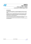
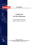
3.1. General Description
The ProDAQ 3511 8-Ch. 200 kS/s DAC Function Card provides eight independent DAC channels
per card. Each channel is equipped with its own 16-bit DAC, gain/offset correction, filter and output
buffer. The output levels of the DACs can be either set directly under program control or
automatically updated from an on-board FIFO.
8CH DAC
Offset Cal.
16bit DAC
Filter / Buffer
Ch.1
8CH DAC
Gain Cal.
16bit DAC
Filter / Buffer
Ch.2
16bit DAC
Filter / Buffer
Ch.3
16bit DAC
Filter / Buffer
Ch.4
16bit DAC
Filter / Buffer
Ch.5
16bit DAC
Filter / Buffer
Ch.6
16bit DAC
Filter / Buffer
Ch.7
16bit DAC
Filter / Buffer
Ch.8
EEPROM
ProDAQ Bus
(Cal.Data)
Function Card
Controller
FIFO
(256 kS)
Trig.
Out
Trig.
In
Clock
Out
Clock
In
Figure 4 - ProDAQ 3511 Block Diagram
The per-channel filter is a programmable two-pole Sallen-and-Key Bessel filter. The cut-off
frequencies can be programmed to be 200 Hz, 2 kHz, 20 kHz or bypass. The cut-off frequency
Copyright, 2007-2008 Bustec Production Ltd.
Page 15 of 46
3511-XX-UM
ProDAQ 3511 8-Ch. 200 kS/s DAC Function Card User Manual
setting is common to all channels. Each channel is equipped with a reed relay directly at the output,
which allows to switch the output pin on the connector between the output of the buffer and ground
to disconnect the output and provide a defined level for equipment connected to the output pin.
The gain and offset correction for each channel individually is done in hardware by two 10-bit DACs
per channel. The calibration data (gain and offset correction coefficients) is stored in an on-board
EEPROM when the card is calibrated in the factory and applied at start-up.
3.2. Direct Write to Channel
Each of the eight DACs can be addressed individually via a register in the function card's address
space. Two update modes are available: sequential and simultaneous. If the sequential update
mode is selected, a write access to each one of the registers updates the corresponding DACs
setting immediately. In simultaneous mode, all write accesses to the registers are first stored in the
function card controller. Upon accessing a certain channel, which can be selected upfront, the
controller updates all channels simultaneously.
3.3. Waveform Generation
To generate a waveform, the FIFO can be used to store data to update the channels automatically
by the on-board controller. Eleven update rates between 100 Hz and 200 kHz can be chosen
(100Hz, 200Hz, 500Hz, ... , 50kHz, 100 kHz, 200 kHz). The update rate is common to all channels.
During the waveform generation, the application can re-fill the FIFO to generate a continuous
waveform. To do so, either it can poll the number of samples left in the FIFO or it can react on a
trigger signal and/or interrupt, which can be generated if the number of samples in the FIFO has
fallen below a programmed level. During waveform generation, no direct write operation to a
channel can be performed.
Waveform generation can be started either direct on a software command (write to a register) or
can be armed to start after detecting a trigger.
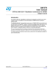
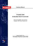
3.4. Trigger
The ProDAQ 3511 can receive trigger signals via the function card trigger input from the
motherboard ("MB Trigger Input") or from the trigger input on the front-panel connector ("FP
Trigger Input"). A received trigger can be used to start the generation of a continuous waveform
("Generation Trigger"). In addition, such a trigger can be generated by software ("SoftTrig").
The trigger signal received (or generated) can be forwarded to other instruments either via the
trigger output on the front-panel connector ("FP Trigger Output") or via the motherboard trigger
routing facilities ("MB Trigger Output"). The routing via the motherboard can only be chosen, if the
trigger output to the motherboard is not already used to forward the trigger signal from the FIFO
("FIFO trigger").
See Figure 5 for an overview of the trigger routing scheme on the ProDAQ 3511 function card.
Page 16 of 46
Copyright, 2007-2008 Bustec Production Ltd.
ProDAQ 3511 8-Ch. 200 kS/s DAC Function Card User Manual
3511-XX-UM
Figure 5 - Trigger Routing Scheme
Copyright, 2007-2008 Bustec Production Ltd.
Page 17 of 46
3511-XX-UM
ProDAQ 3511 8-Ch. 200 kS/s DAC Function Card User Manual
(This page was intentionally left blank.)
Page 18 of 46
Copyright, 2007-2008 Bustec Production Ltd.
ProDAQ 3511 8-Ch. 200 kS/s DAC Function Card User Manual
3511-XX-UM
4. The VXIplug&play Driver
4.1. Installation
The ProDAQ 3511 8-Ch. 200 kS/s DAC function card is supplied with a VXIplug&play driver. To
install the driver, run the “Setup.exe” application coming with it and follow the instructions
presented. Make sure that no other ProDAQ software is running when you start the set up.
The installation program by default performs a complete installation. It installs the driver files in the
directory tree defined by the %VXIPNPPATH% environment variable and the shortcuts into the
VXIPNP program group of the start menu. To choose a different path and/or custom installation
options is not recommended and may result in malfunctioning of the soft front panel and any
application trying to use the driver.
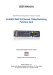
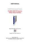
4.2. The Soft Front Panel
The purpose of soft front panel application is to demonstrate the instrument’s abilities. After the
start of the soft front panel application, the user will be presented with a dialog box showing all
available ProDAQ 3511 instruments in a system, allowing the selection of one instrument to
connect to. The soft front panel is not designed to handle more then one instrument at a time. If
there is only one instrument available, the dialog box will not appear and the soft front panel
application will automatically establish the communication to this instrument.
If no ProDAQ 3511 is available in your system, the soft front panel application can be run in demo
mode, allowing to operate all controls as if connected to a function card.
Figure 6 - ProDAQ 3511 Soft Front Panel Application
Copyright, 2007-2008 Bustec Production Ltd.
Page 19 of 46
3511-XX-UM
ProDAQ 3511 8-Ch. 200 kS/s DAC Function Card User Manual
After initializing the ProDAQ 3511 function card, during which a splash screen is displayed, the soft
front panel window will appear (see Figure 6). Using the two tab panels displayed the user can
select graphical interfaces representing the two top-level functions implemented by the
VXIplug&play driver: waveform generation and direct write to a channel.
4.2.1. Waveform Generation
The controls on the “Waveform Generation” page allow generating a pre-defined waveform on
selected channels. For each channel, the waveform type (sine, square, saw tooth and triangle), the
amplitude and the offset can be chosen. Channels must be enabled by the checkboxes in the
"Select Channel" group.
The waveform generated by the soft front panel application uses 2048 samples per period.
Together with the update frequency, which can be chosen using the "DAC Update Freq" control,
this defines the frequency of the generated waveform. The cur-off frequency of the output filters
can be controlled using the "Filter" control in the same group.
The waveform generation is started by selecting the “Start” button. Depending on the setting of the
"Generate" control, either a single cycle or a continuous waveform will be generated. If a
continuous waveform is generated, the generation can be stopped by selecting the "Stop" button.
4.2.2. Direct Write to Channel
The controls on the “Write Channel” page allow updating the output of each DAC manually.
Figure 7 - Write Channel Page
Changing the setting of one of the controls will result in an immediate update of the DAC value.
Page 20 of 46
Copyright, 2007-2008 Bustec Production Ltd.
ProDAQ 3511 8-Ch. 200 kS/s DAC Function Card User Manual
3511-XX-UM
5. Programming the ProDAQ 3511
This chapter shows how to program the ProDAQ 3511 DAC function card using the VXIplug&play
driver. Complete examples can be found in the “Examples” subdirectory of the driver. All functions
are explained in detail in the help file coming with the driver.
5.1. Connecting to the Function Card
To initialize the driver and connect to the ProDAQ motherboard, the standard VXIplug&play
initialization function bu3511_init() is used (see Figure 8, ). (Please refer to the VXIplug&play
standard VPP-4.3, section 4.3 for a detailed description of the address string used.)
After initializing the driver and connecting to the motherboard, the driver must be told which one of
the eight possible function cards on a ProDAQ motherboard to work with. This is done by the
function bu3511_fcSelect(). It takes as an argument the session established via the function
bu3511_init(), the function card number and a boolean value specifying whether to reset the
selected function card (see Figure 8,).
#include <visa.h>
#include <bu3511.h>
main (int argc, char **argv)
{
ViStatus status;
ViSession session;
ViChar descr[256];
if ((status = bu3511_init(“VXI0::2::INSTR”, VI_TRUE, VI_TRUE, &session)) != VI_SUCCESS)
{
viStatusDesc (rm_session, status, descr);
printf (“Error: bu3511_init() failed due to %s\n”, descr);
return -1;
}
if ((status = bu3511_fcSelect(session, 1, VI_TRUE)) != VI_SUCCESS)
{
viStatusDesc (instr_session, status, descr);
printf (“Error: bu3511_fcSelect failed due to %s\n”, descr);
return -1;
}
/* OR: */
if ((status = bu3511_paramInit(“VXI0::2::INSTR”, 1, VI_TRUE, VI_TRUE, &session)) != VI_SUCCESS)
{
viStatusDesc (rm_session, status, descr);
printf (“Error: bu3511_paramInit() failed due to %s\n”, descr);
return -1;
}
/* ... */
Figure 8 - Opening a Session
For your convenience, the driver contains a new function called bu3511_paramInit(), which
combines the functionality of the bu3511_init() and bu3511_fcSelect() functions by extending
the argument list of the standard initialization function with a parameter specifying the function card
number (see Figure 8,).
Copyright, 2007-2008 Bustec Production Ltd.
Page 21 of 46
3511-XX-UM
ProDAQ 3511 8-Ch. 200 kS/s DAC Function Card User Manual
For the driver functions to work properly, you will either have to use the function
bu3511_paramInit() to open a session with the device, or you will have to call the function
bu3511_fcSelect()after calling the function bu3511_init() and before any other driver function
is called.
To close a session with the ProDAQ 3511 function card, the standard VXIplug&play function
bu3511_close() must be used.
5.2. Using Direct Write to Channels
The VXIplug&play driver for the ProDAQ 3511 function card provides two functions for the direct
write access to the eight channels – bu3511_writeChannel() and bu3511_writeChannels().
The function bu3511_writeChannel() allows you to update a single channel (see Figure 9, ),
while the function bu3511_writeChannels() updates multiple channel simultaneously (see Figure
9, ). The channels to update are defined via a channel mask – an integer value where the lower 8
bits correspond to the 8 channels available on the 3511. Each of these bits set to "1" will include
the channel in the update. The data array passed to the function must always have a size of eight
with the data placed at the correct location for the channels selected in the channel mask.
/* ... */
/* select a filter cut-off frequency of 10 kHz for all channels */
if ((status = bu3511_setFilter (session, bu3511_FILT_BYPASS)) < VI_SUCCESS)
{
bu3511_error_message (rm_session, status, descr);
printf (“Error: bu3511_ setFilter() failed due to %s\n”, descr);
return -1;
}
/* enable the output on channels 1, 3 and 5) */
if ((status = bu3511_setOutputEnable (session, 0x15)) != VI_SUCCESS)
{
bu3511_error_message (instr_session, status, descr);
printf (“Error: bu3511_setOutputEnable() failed due to %s\n”, descr);
return -1;
}
/* set channel 1 to 5.2V output */
if ((status = bu3511_writeChannel (session, bu3511_CHAN_1, 5.2)) != VI_SUCCESS)
{
bu3511_error_message (rm_session, status, descr);
printf (“Error: bu3511_writeChannel () failed due to %s\n”, descr);
return -1;
}
/* update channels 1, 3 and 5 simultaneously */
data[0] = 1.2; data[2] = 3.7; data[4] = 8.1;
if ((status = bu3511_writeChannels (session, 0x15, data)) != VI_SUCCESS)
{
bu3511_error_message (rm_session, status, descr);
printf (“Error: bu3511_writeChannels () failed due to %s\n”, descr);
return -1;
}
/* ... */
Figure 9 - Using Direct Write to Channels
Page 22 of 46
Copyright, 2007-2008 Bustec Production Ltd.
ProDAQ 3511 8-Ch. 200 kS/s DAC Function Card User Manual
3511-XX-UM
No output will be generated on channels not first enabled via the bu3511_setOutputEnable()
function (see Figure 9, ). As the bu3511_writeChannels() function, this function accepts a
mask where the lower 8 bits correspond to the channel t which shall be enabled.
The function bu3511_setFilter()can be used to select the cut-off frequency of the output filters
before updating the outputs.
5.3. Waveform Generation
To generate a waveform using the ProDAQ 3511 8-Ch. 200kS/s DAC function card, a number of
different driver functions can be used. If they allow generating waveforms on more then one
channel, they accept the waveform data in two different formats: Grouped by channel or grouped
by scan. If grouped by channel is specified (bu3511_GROUP_BY_CHANNEL), the data in the linear
array passed to the function must first contain all data for the first channel specified in the channel
mask, the all data for the second channel specified in the channel mask etc:
Ch. 1 Value 1
Ch. 1 Value 2
Ch. 1 Value 3
Ch. 1 Value 4
Ch. 1 Value 5
Ch. 2 Value 1
Ch. 2 Value 2
Ch. 2 Value 3
Ch. 2 Value 4
Ch. 2 Value 5
Ch. 5 Value 1
Ch. 5 Value 2
Ch. 5 Value 3
Ch. 5 Value 4
Ch. 5 Value 5
Ch. 7 Value 1
Ch. 7 Value 2
Ch. 7 Value 3
Ch. 7 Value 4
Ch. 7 Value 5
0
1
2
3
4
5
6
7
8
9
10
11
12
13
14
15
16
17
18
19
Array Index
If grouped by scan is specified (bu3511_GROUP_BY_SCAN), the data in the array must start with the
first values for all channels (sorted by channel number, lower to higher number), then the second
values for all channels etc:
Ch. 1 Value 1
Ch. 2 Value 1
Ch. 5 Value 1
Ch. 7 Value 1
Ch. 1 Value 2
Ch. 2 Value 2
Ch. 5 Value 2
Ch. 7 Value 2
Ch. 1 Value 3
Ch. 2 Value 3
Ch. 5 Value 3
Ch. 7 Value 3
Ch. 1 Value 4
Ch. 2 Value 4
Ch. 5 Value 4
Ch. 7 Value 4
Ch. 1 Value 5
Ch. 2 Value 5
Ch. 5 Value 5
Ch. 7 Value 5
0
1
2
3
4
5
6
7
8
9
10
11
12
13
14
15
16
17
18
19
Array Index
5.3.1. Limited Waveform Generation
The driver functions bu3511_generateWaveform() and bu3511_generateWaveforms() can be
used to generate a waveform which length is limited by the on-board FIFO. The waveform passed
to the functions is loaded into the FIFO, the card is configured for the selected update speed,
channel pattern and filter setting and the generation is started immediately.
While the function bu3511_generateWaveform()can only generate a waveform on one channel,
the function bu3511_generateWaveforms()allows to generate the waveform on multiple channels.
The list of channels is defined by a channel mask similar to the one used for the function
bu3511_writeChannels() shown above. See Figure 10 for an example of both functions.
Copyright, 2007-2008 Bustec Production Ltd.
Page 23 of 46
3511-XX-UM
ProDAQ 3511 8-Ch. 200 kS/s DAC Function Card User Manual
{
ViSession session;
ViInt16 i, j;
ViReal64 data[2000];
/* .... */
/* Create ten periods sine wave in the buffer. Each period has a length of 100 samples
* and the sine wave will have an amplitude of 2V.
*/
for(i = 0; i < 1000; i++)
data[i] = 2.0 * sin(2.0*PI*i/100);
/* Write the data into the FIFO and start waveform generation on channel 1 */
if ((status = bu3511_generateWaveform (session, bu3511_CHAN_1,
1000, bu3511_CLK_INTERNAL_20KHZ,
bu3511_FILT_2KHZ, data)) < VI_SUCCESS)
{
bu3511_error_message (rm_session, status, descr);
printf (“Error: bu3511_generateWaveform () failed due to %s\n”, descr);
return -1;
}
/* wait for the first waveform generation to finish */
do
{
if ((status = bu3511_getStatus (session, fifo_status, NULL)) < VI_SUCCESS)
{
/* ... */
}
}
while (fifo_status != bu3511_FIFO_EMPTY);
/* stop the generation */
if ((status = bu3511_stopWaveformGeneration (session)) < VI_SUCCESS)
{
/* ... */
}
/* Create in addition a square wave with an amplitude of 2.5V. To generate a waveform
* on multiple channels, all data sets must have the same length.
*/
for (i = 1000; i < 2000; )
{
for (j = 0; j < 50; i++)
data[i++] = 2.5;
for (j = 0; j < 50; i++)
data[i++] = -2.5;
}
/*
* Now we have data for two channels in the array, sorted by channel:
*
* |- data ch1 -||- data ch3 -|
*
* Write the data into the FIFO and start waveform generation on
* channel 1 and 3
*/
if ((status = bu3511_generateWaveforms (session, 0x05, 1000,
bu3511_CLK_INTERNAL_50KHZ, bu3511_FILT_20KHZ,
bu3511_GROUP_BY_CHANNEL, data)) < VI_SUCCESS)
{
/* ... */
}
/* ... */
}
Figure 10 – Limited Waveform Generation
Page 24 of 46
Copyright, 2007-2008 Bustec Production Ltd.
ProDAQ 3511 8-Ch. 200 kS/s DAC Function Card User Manual
3511-XX-UM
5.3.2. Continuous Waveform Generation
To generate a continuous waveform the FIFO must be refilled during the generation. To allow this,
the driver features a set of functions, which allow the application to react on the remaining amount
of data in the FIFO, either by polling a status or by receiving an interrupt.
Figure 11 shows an example of continuous waveform generation using polling. First, the data array
is filled with two waveforms, each with a length of 100000 samples. Both waveforms are sine
waves, one with an amplitude of 2 volts, no offset; the other one with an amplitude of 1V and an
offset of 1V. The data is sorted by scans. (see Figure 11, )
{
ViSession session;
ViInt32 i, l, fifo_status, nsamples;
ViReal64 data[256 * 1024];
/* .... */
/*
* Fill the array with waveform data for two channels, sorted by scan.
*/
for(l = 0, i = 0; l < 100000; l++)
{
data[i++] = 2.0 * sin(2.0*PI*l/100) + 0.0;
data[i++] = 1.0 * sin(2.0*PI*l/100) + 1.0;
}
/* channel 1 */
/* channel 3 */
/* Write the data into the FIFO and start waveform generation on channels 1 & 3*/
if ((status = bu3511_startContWaveform (session, 0x05, 100000,
bu3511_CLK_INTERNAL_50KHZ, bu3511_FILT_20KHZ,
bu3511_GROUP_BY_SCAN, 0, data)) < VI_SUCCESS)
{
/* ... */
}
/* generate the waveform for 60 sec total */
for (i = 0; i < 58; i++)
{
do
{
/*
* poll the amount of samples in the FIFO. The returned value is
* the total amount of samples, !not! samples per waveform.
*/
if ((status = bu3511_getStatus (session, &fifo_status,
&nsamples)) < VI_SUCCESS)
{
/* ... */
}
}
while (nsamples > 100000);
/* Re-fill FIFO */
if ((status = bu3511_writeWaveform (session, 50000, 2,
bu3511_GROUP_BY_SCAN, data)) < VI_SUCCESS)
{
/* ... */
}
}
/* ... */
}
Figure 11 - Continuous Waveform Generation with Polling
Copyright, 2007-2008 Bustec Production Ltd.
Page 25 of 46
3511-XX-UM
ProDAQ 3511 8-Ch. 200 kS/s DAC Function Card User Manual
Then the function bu3511_startContWaveform() is used to configure the function card for
waveform generation on channels 1 and 3 with an update frequency of 50 kHz and a filter cut-off
frequency of 20 kHz (see Figure 11, ). The function also fills the FIFO with the initial set of
waveform data - here the two waveforms calculated above. As each waveform has a length of
100000 samples, the FIFO contains now a total of 200000 samples. After configuring the card and
filling the FIFO with waveform data, the waveform generation is started immediately.
To generate a continuous waveform, the FIFO now needs to be refilled, whenever the amount of
data in it reaches a certain level. In the example the function bu3511_getStatus() is used to poll
the amount of data left in the FIFO (see Figure 11, ). The function returns the amount of data in
the FIFO as the total amount of samples in it, so the loop in the example waits for it to become less
than half of the initial amount of 200000 samples before attempting to refill the FIFO.
The refilling is done by using the function bu3511_writeWaveform(). In the example simply the
first half of the waveform data initially calculated is written again into the FIFO every time more
than half of the data was used for the waveform generation (see Figure 11, ).
At any time during the process, the waveform generation can be stopped by using the function
bu3511_stopWaveformGeneration(). As shown in the example in Figure 10, , the function
bu3511_getStatus() can be used to wait until all remaining data from the FIFO was used by
waiting for the FIFO status to become bu3511_FIFO_EMPTY. You should always stop the waveform
generation explicitly, as an empty FIFO is an error condition during waveform generation and will
not cause the card to reset itself into an idle state.
In the example above the FIFO status was polled, therefore a value of zero was passed to the
"threshold" parameter. If a value of 50000 would have been specified (half the initial waveform
length), a trigger signal would have been generated every time the amount of data in the FIFO
would have been fallen below the threshold. This trigger can be routed via the motherboard trigger
routing facilities onto the VXIbus trigger lines or it can be used to generate an interrupt. Both
trigger and/or interrupts events can then be used by the event handling functions of the VISA
library either to wait for this event or to asynchronously call a callback function. For your
convenience, the function bu3511_startContWaveformEx() is provided in the driver, which
accepts as an additional parameter the address of a callback function to be called when the FIFO
threshold is reached. The function applies the necessary configuration and installs the event
handler. In the callback function simply the next part of the waveform data needs to be written to
the FIFO. See the example GenerateWaveformContEx.c coming with the driver.
Page 26 of 46
Copyright, 2007-2008 Bustec Production Ltd.
ProDAQ 3511 8-Ch. 200 kS/s DAC Function Card User Manual
3511-XX-UM
Appendix A: Register Description
A.1 Address Map
All addresses are given in a hexadecimal notation. “FC Address” specifies the address in the
internal function card address space of the motherboard. “VXI Offset” is the offset to be used when
accessing this register directly via the function card space mapped into the VXI memory space of
the motherboard.
VXI Offset
FC Address
Name
Access
Function
0
0
FCID
RO
ID for automatic board identification
4
1
FCVER
RO
Version numbers
8
2
FCCSR
14
5
TRIG
RW
Trigger configuration
18
6
TEST
RW
Test interface with VXI bus
1C
7
CALIB_DAC
RO/WO
20
8
SCAN
RW
Set channels for FIFO scan
24
9
RELAY
RW
Output relay control
28
A
FREQ
WO
Update rate and clock source
2C
B
FIFO_STATUS
RO
Number of samples in FIFO memory
30
C
FIFO_CTRL
RO/WO
34
D
FIFO_TRG
WO
Set FIFO interrupt threshold
200 21C
80 87
MAIN_DAC
WO
Output DAC setting
3E8
FA
EE_DATA
RW
EEPROM data access
3EC
FB
EE_CTRL
RO/WO
3F0
FC
FCSUB
RO
Subtype
3F8
FE
FCSERH
RO
Upper 16-bits of serial number
3FC
FF
FCSERL
RO
Lower 16-bits of serial number
20000
8000
FIFO
WO
Write to FIFO
RO/RW/
General control and status
RWC/WO
Set offset and gain calibration DACs
FIFO control and status register
EEPROM control
All registers are 16-bit wide.
Copyright, 2007-2008 Bustec Production Ltd.
Page 27 of 46
3511-XX-UM
ProDAQ 3511 8-Ch. 200 kS/s DAC Function Card User Manual
A.2 Detailed Register Description
A.1.1 FCID Register
The function card ID register contains a unique number used to identify the card.
Bit
15
14
13
12
11
10
9
8
7
6
5
4
3
2
1
0
Operation
RO
RO
RO
RO
RO
RO
RO
RO
RO
RO
RO
RO
RO
RO
RO
RO
Initial
0
1
1
1
0
0
0
0
0
1
1
1
0
0
0
0
Function Card ID (0x3511)
Content
A.1.2 FCVER
This register contains the PCB version number and the FPGA version number.
Bit
15
14
13
12
11
10
9
8
7
6
5
4
3
2
1
0
Operation
RO
RO
RO
RO
RO
RO
RO
RO
RO
RO
RO
RO
RO
RO
RO
RO
Initial
-
-
-
-
-
-
-
-
-
-
-
-
-
-
-
-
Major
Content
Minor
Major
FPGA version
Minor
PCB version
A.1.3 FCCSR
13
12
11
10
9
8
7
6
5
4
3
2
Operation
RW
RW
RW
RW
-
-
-
-
RW
RW
RW
RW
RW
RW
Initial
0
0
0
0
-
-
-
-
1
1
1
0
1
1
Content
FrequencyError
FIFOEmptyError
FIFOFullError
MainDACReset
Not Used
UpdateChannel
FilterValue
1
0
RO RWC
0
0
MainDACReset
14
MainDACBusy
15
Simultaneous
Bit
Generation
Function card control and status register.
Resets the function card to a known status. After reset all outputs are switched
to ground via the output relays.
Write:
0 - no effect
1 - reset
Read:
0 - reset is finished
Page 28 of 46
Copyright, 2007-2008 Bustec Production Ltd.
ProDAQ 3511 8-Ch. 200 kS/s DAC Function Card User Manual
MainDACBusy
3511-XX-UM
The bit indicates the status of the main DACs shift registers.
Write:
No effect
Read:
0 - board ready to accept next DAC setting
1 - board busy; writing to DAC register will be ignored
FilterValue
Selects one of the following cut-off frequencies for the DAC output filters
(range: 0..3)
Write:
0 – 200Hz
1 – 2kHz
2 – 20kHz
3 – bypass (no filter) (default)
Read:
Returns previously written value
Note: the cut-off frequency is common for all DAC channels.
Simultaneous
This bit selects between a simultaneous and a sequential update of all DAC
channels.
Write:
0 – sequential update
1 – simultaneous update
Read:
Returns previously written value
UpdateChannel
These bits select the channel to which an access updates outputs of all DAC
channels in the case of a simultaneous update mode i.e. when Simultaneous
bit in FCCSR is set (range: 0..7).
Write:
0 – Channel number 1
1 – Channel number 2
2 – Channel number 3
3 – Channel number 4
4 – Channel number 5
5 – Channel number 6
6 – Channel number 7
7 – Channel number 8 (default)
Read:
Returns previously written value
FIFOFullError
This bit indicates that an access to a completely full FIFO occurred and the
data was lost.
Write:
0 – no effect
1 – clears the flag
Read:
0 – no error occurred
1 – indicates an error
Copyright, 2007-2008 Bustec Production Ltd.
Page 29 of 46
3511-XX-UM
FIFOEmptyError
ProDAQ 3511 8-Ch. 200 kS/s DAC Function Card User Manual
This bit indicates that a generation process requested data from an empty
FIFO.
Write:
0 – no effect
1 – clears the flag
Read:
0 – no error occurred
1 – indicates an error
FrequencyError
This bit indicates that a clock connected to the front panel exceeds the
maximum update frequency.
Write:
0 – no effect
1 – clears the flag
Read:
0 – no error occurred
1 – indicates an error
Generation
This bit starts a generation process for channels selected by SCAN register
involving the FIFO memory.
Write:
0 – stops a generation (after completing the current scan)
1 – starts (or arms) a generation
Read:
0 – a generation stopped
1 – a generation in process (armed and triggered)
Note: If a generation trigger is activated (GenTrigEn bit in TRIG register is set)
then the Generation bit in FCCSR register aonly arms the generation process
and the actual generation will start after the trigger event happens, otherwise
the generation starts at once.
Page 30 of 46
Copyright, 2007-2008 Bustec Production Ltd.
ProDAQ 3511 8-Ch. 200 kS/s DAC Function Card User Manual
3511-XX-UM
A.1.4 TRIG
Bit
15
14
13
12
11
10
9
8
7
6
5
4
3
2
1
0
Operation
RO
RO
RO
RO
-
-
-
-
-
RW
RW
RW
RW
RW
RW
RW
Initial
0
0
0
0
-
-
-
-
-
0
0
0
0
0
0
0
Content
MBTrigIn
MBTrigOut
FPTrigIn
FPTrigOut
FIFOTrigEn
GenTrigEn
MBTrigInEn
MBTrigOutEn
FPTrigInEn
FPTrigOutEn
SoftTrig
This register defines the trigger configuration. The settings in this register control the generation of
trigger events.
SoftTrig
Not used
Software trigger.
Write:
0 – de-asserts trigger
1 – asserts trigger
Read:
0 – trigger not active
1 – trigger asserted
FPTrigOutEn
Controls the front panel trigger output.
Write:
0 – disables output
1 – enables output
Read:
0 - output disabled
1 - output enabled
FPTrigInEn
Controls the front panel trigger input.
Write:
0 – disables input
1 – enables input
Read:
0 - input disabled
1 - input enabled
MBTrigOutEn
Controls the trigger output to the motherboard.
Write:
0 – disables output
1 – enables output
Read:
0 – output disabled
1 – output enabled
MBTrigInEn
Controls the trigger input from the motherboard.
Copyright, 2007-2008 Bustec Production Ltd.
Page 31 of 46
3511-XX-UM
ProDAQ 3511 8-Ch. 200 kS/s DAC Function Card User Manual
Write:
0 – disables input
1 – enables input
Read:
0 – input disabled
1 – input enabled
GenTrigEn
Controls the trigger starting a generation process. Used to synchronise
generation on multiple cards.
Write:
0 – disables trigger
1 – enables trigger
Read:
0 – trigger disabled
1 – trigger enabled
Note: If GenTrigEn bit is set then a generation process will not start until any
enabled input trigger happens.
FIFOTrigEn
Select a trigger source for the motherboard trigger output.
Write:
0 – disables the trigger from FIFO and enables from other sources
1 – enables the trigger from FIFO and disables from other sources
Read:
0 – FIFO trigger disabled
1 – FIFO trigger enabled
FPTrigOut
This bit indicates the status of the FP trigger output line.
Write:
No effect
Read:
0 – trigger line inactive
1 – trigger line active
FPTrigIn
This bit indicates the status of the FP trigger input line.
Write:
No effect
Read:
0 – trigger line inactive
1 – trigger line active
MBTrigIn
This bit indicates the status of the MB trigger input line.
Write:
No effect
Read:
0 – trigger line inactive
1 – trigger line active
Page 32 of 46
Copyright, 2007-2008 Bustec Production Ltd.
ProDAQ 3511 8-Ch. 200 kS/s DAC Function Card User Manual
3511-XX-UM
A.1.5 TEST
Bit
15
14
13
12
11
10
9
8
7
6
5
4
3
Operation
RW
RW
RW
RW
RW
RW
RW
RW
RW
RW
RW
RW
RW
Initial
1
1
1
1
1
1
1
1
1
1
1
1
1
4
3
2
1
RW RW
1
0
RW
1
1
TestRegister
Content
TestRegister
Read and write register with no functionality.
Write:
No effect
Read:
Returns previously written value
A.1.6 CALIB_DAC
Bit
15
14
13
Operation
RO
WO
-
Initial
-
-
-
Content
CalibDACBusy
GainSelect
Not Used
This register allows setting the offset and gain calibration DACs directly.
CalibValue
12
11
10
9
8
7
6
5
2
1
0
WO WO WO WO WO WO WO WO WO WO WO WO WO
-
-
-
-
-
-
CalibAddress
-
-
-
-
-
-
-
CalibValue
Code to be sent to DAC.
Write:
Ten-bit calibration DAC value (range: 0..1023)
Read:
No effect
CalibAddress
Select which channel to calibrate.
Write:
Channel address (range: 0..7)
Read:
No effect
GainSelect
Select between gain and offset.
Write:
0 - calibrate offset
1 - calibrate gain
Read:
No effect
Copyright, 2007-2008 Bustec Production Ltd.
Page 33 of 46
3511-XX-UM
ProDAQ 3511 8-Ch. 200 kS/s DAC Function Card User Manual
CalibDACBusy
This bit indicates the status of the shift register to the calibration DAC.
Write:
No effect
Read:
0 - board ready to accept next CALIB_DAC setting
1 - board busy and writing to CALIB_DAC register will be ignored
A.1.7 SCAN
Defines which channels take part in update from FIFO.
8
Operation
-
-
-
-
-
-
-
-
Initial
-
-
-
-
-
-
-
-
Not used
Content
ScanCh0..7
7
6
5
4
3
2
1
0
RW RW RW RW RW RW RW RW
0
0
0
0
0
0
0
0
ScanCh0
9
ScanCh1
10
ScanCh2
11
ScanCh3
12
ScanCh4
13
ScanCh5
14
ScanCh6
15
ScanCh7
Bit
These bits select particular channels for acquisition involving FIFO.
Write:
0 – disables channel
1 – enables channel
Read:
Returns previously written value
Note: order is always from lower to higher number of channel, therefore
0x00AA (binary 1010 1010) means that four (4) channels take part in the
generation process and the data in the FIFO is stored in following order: Ch1,
Ch3, Ch5, Ch7, Ch1, Ch3, Ch5...
A.1.8 RELAY
Controls which channels are connected to the front panel connector.
8
Operation
-
-
-
-
-
-
-
-
Initial
-
-
-
-
-
-
-
-
Not used
Content
RelayCh0..7
7
6
5
4
3
2
1
0
RW RW RW RW RW RW RW RW
0
0
0
0
0
0
0
0
RelayCh0
9
RelayCh1
10
RelayCh2
11
RelayCh3
12
RelayCh4
13
RelayCh5
14
RelayCh6
15
RelayCh7
Bit
These bits connects the channel outputs to the FP connector.
Write:
0 – disconnects channel output (default)
1 – connects channel output
Page 34 of 46
Copyright, 2007-2008 Bustec Production Ltd.
ProDAQ 3511 8-Ch. 200 kS/s DAC Function Card User Manual
3511-XX-UM
Read:
Returns previously written value
A.1.9 FREQ
Sets the update rate of DAC outputs.
13
12
11
10
9
8
7
Operation
-
-
-
-
-
-
-
-
-
Initial
-
-
-
-
-
-
-
-
-
Content
FreqValue
6
5
4
3
2
1
0
RW RW RW RW RW RW RW
0
0
0
FreqSource
14
FPClkOutEn
15
FPClockEdge
Bit
0
0
0
0
FreqValue
Selects one of the following update rates for DAC outputs in generation mode
(range: 0..10)
Write:
0
1
2
3
4
5
6
7
8
9
10
-
200
100
50
20
10
5
2
1
500
200
100
kHz
kHz
kHz
kHz
kHz
kHz
kHz
kHz
Hz
Hz
Hz
Read:
No effect
Note: the update rate is common for all DAC channels.
FreqSource
The bit selects the clock source for a generation process.
Write:
0 – clock generated onboard, frequency set by FreqValue
1 – clock incoming from the front panel connection
Read:
Returns previously written value
Note: If the clock source from front panel is out of range (too fast) then the
card generates an error and sets the FrequencyError bit in FCCSR register.
Note: It is possible to select the polarity of the incoming clock from the front
panel by setting the FPClockEdge bit.
Copyright, 2007-2008 Bustec Production Ltd.
Page 35 of 46
3511-XX-UM
ProDAQ 3511 8-Ch. 200 kS/s DAC Function Card User Manual
FPClkOutEn
The bit allows the on board clock to be connected to the front panel.
Write:
0 – disconnects clock (default)
1 – connects clock
Read:
Returns previously written value
FPClockEdge
The bit allows selects the active edge of the incoming clock from the front
panel. It does not affect the clock generated onboard.
Write:
0 – rising edge clocks a generation (low to high transition)
1 – falling edge clocks a generation (high to low transition)
Read:
Returns previously written value
A.1.10 FIFO_STATUS
Indicates the amount of samples available in the FIFO memory.
Bit
15
14
13
12
11
10
9
8
7
6
5
4
3
2
1
0
Operation
RO
RO
RO
RO
RO
RO
RO
RO
RO
RO
RO
RO
RO
RO
RO
RO
Initial
0
0
0
0
0
0
0
0
0
0
0
0
0
0
0
0
FIFOStatus[15..0]
Content
FIFOStatus
This register indicates the contents of the FIFO memory.
Write:
No effect
Read:
Returns the amount of samples stored in FIFO memory (less
significant 16 of total 18 bits).
A.1.11 FIFO_CTRL
14
13
12
11
10
9
8
7
6
5
4
3
2
1
0
Operation
RO
RO
WO
WO
-
-
-
-
-
-
-
-
RO
RO
RO
WO
Initial
0
0
0
0
-
-
-
-
-
-
-
-
0
0
1
0
FIFOHalfFull
FIFOEmpty
ClearFIFO
Content
Page 36 of 46
FIFOTrg[17..16]
15
FIFOStatus[17..16]
Bit
FIFOFull
FIFO control and status register.
Not used
Copyright, 2007-2008 Bustec Production Ltd.
ProDAQ 3511 8-Ch. 200 kS/s DAC Function Card User Manual
ClearFIFO
3511-XX-UM
The bit allows clearing of the FIFO contents and all related flags.
Write:
0 – no effect
1 – clears the FIFO memory
Read:
No effect
FIFOEmpty
The bit indicates that the FIFO is empty.
Write:
No effect
Read:
0 – FIFO not empty
1 – FIFO empty
FIFOHalfFull
The bit indicates that the FIFO is half full.
Write:
No effect
Read:
0 – FIFO less than half full
1 – FIFO half full
FIFOFull
The bit indicates that the FIFO is full.
Write:
No effect
Read:
0 – FIFO not full
1 – FIFO full
FIFOTrg
The remaining 2 most significant bits of the 18-bit FIFO_TRG register.
Write:
Selects FIFO threshold
Read:
No effect
FIFOStatus
The remaining 2 most significant bits of the 18-bit FIFO_STATUS register.
Write:
No effect
Read:
Amount of samples stored in FIFO memory
Copyright, 2007-2008 Bustec Production Ltd.
Page 37 of 46
3511-XX-UM
ProDAQ 3511 8-Ch. 200 kS/s DAC Function Card User Manual
A.1.12 FIFO_TRG
Selects the threshold at which the FIFO level generates a trigger.
Bit
Operation
Initial
15
14
13
12
11
10
9
8
7
6
5
4
3
2
1
0
WO WO WO WO WO WO WO WO WO WO WO WO WO WO WO WO
0
0
0
0
0
0
0
0
0
0
0
0
0
0
0
0
FIFOTrg[15..0]
Content
FIFOTrg
This register selects a threshold below which a trigger is generated. Setting
the FIFOTrigEn bit in the TRIG register can activate the trigger.
Write:
Selects FIFO threshold (less significant 16 of total 18 bits)
Read:
No effect
A.1.13 MAIN_DAC
These eight registers allow setting the output DACs directly.
Bit
Operation
Initial
15
14
13
12
11
9
8
7
6
5
4
3
2
1
0
WO WO WO WO WO WO WO WO WO WO WO WO WO WO WO WO
-
-
-
-
-
-
-
-
-
-
-
-
-
-
-
-
DACValue
Content
DACValue
10
Value to be sent to the corresponding DAC.
Write:
Sixteen bits DAC value (range: 0..65535)
Read:
No effect
Note: Before issuing new MAIN_DAC value poll the status of the bit
MainDACBusy in FCCSR register.
Note: The registers are not accessible if Generation bit in FCCSR register is
set.
Table 2.9.2.13: Output Voltage Versus Input Code
Page 38 of 46
Input Code
Unipolar Configuration
Bipolar Configuration
0x0000
0x0001
0x8000
0xFFFF
Zero (0V)
+1LSB
0.5 Fullscale
Fullscale (Range – 1LSB)
-Fullscale
-Fullscale + 1LSB
Bipolar Zero (0V)
+Fullscale (Range – 1LSB)
Copyright, 2007-2008 Bustec Production Ltd.
ProDAQ 3511 8-Ch. 200 kS/s DAC Function Card User Manual
3511-XX-UM
A.1.14 EE_DATA
EEPROM data access register. Factory use only.
Bit
Operation
Initial
15
14
13
12
11
10
9
8
7
6
5
4
3
2
1
0
RW RW RW RW RW RW RW RW RW RW RW RW RW RW RW RW
0
0
0
0
0
0
0
0
0
0
0
0
0
0
0
0
1
0
EEPROMValue
Content
A.1.15 EE_CTRL
EEPROM control register, used to read and write the EEPROM data. Factory use only
Bit
Operation
Initial
15
14
13
12
11
10
9
8
7
6
5
4
3
2
RW RW RW RW RW RW RW RW RW RW RW RW RW RW RW RW
0
0
0
0
0
0
0
0
0
0
0
0
0
0
0
0
EEPROMControl
Content
A.1.16 FCSUB
Function card subtype register.
Bit
15
14
13
12
11
10
9
8
7
6
5
4
3
2
1
0
Operation
RO
RO
RO
RO
RO
RO
RO
RO
RO
RO
RO
RO
RO
RO
RO
RO
Initial
-
-
-
-
-
-
-
-
-
-
-
-
-
-
-
-
First letter (ASCII)
Content
Second letter (ASCII)
See datasheet for the different versions of the ProDAQ 3511 function card.
A.1.17 FCSERH
Contains the upper 16-bits of the function card serial number.
Bit
15
14
13
12
11
10
9
8
7
6
5
4
3
2
1
0
Operation
RO
RO
RO
RO
RO
RO
RO
RO
RO
RO
RO
RO
RO
RO
RO
RO
Initial
-
-
-
-
-
-
-
-
-
-
-
-
-
-
-
-
Upper 16-bits of serial number
Content
A.1.18 FCSERL
Contains the lower 16-bits of the function card serial number.
Bit
15
14
13
12
11
10
9
8
7
6
5
4
3
2
1
0
Operation
RO
RO
RO
RO
RO
RO
RO
RO
RO
RO
RO
RO
RO
RO
RO
RO
Initial
-
-
-
-
-
-
-
-
-
-
-
-
-
-
-
-
Content
Lower 16-bits of serial number
Copyright, 2007-2008 Bustec Production Ltd.
Page 39 of 46
3511-XX-UM
ProDAQ 3511 8-Ch. 200 kS/s DAC Function Card User Manual
A.1.19 FIFO
Allows writing data into FIFO memory.
Bit
Operation
Initial
Content
Page 40 of 46
15
14
13
12
11
10
9
8
7
6
5
4
3
2
1
0
WO WO WO WO WO WO WO WO WO WO WO WO WO WO WO WO
-
-
-
-
-
-
-
-
-
-
-
-
-
-
-
-
FIFOReg
Copyright, 2007-2008 Bustec Production Ltd.
ProDAQ 3511 8-Ch. 200 kS/s DAC Function Card User Manual
3511-XX-UM
Appendix B: Front Panel Connector
The front panel connector used on the ProDAQ 3511 is a 50-pin female SCSI with the following
pin-out:
1
25
top
26
50
Copyright, 2007-2008 Bustec Production Ltd.
Signal
A
B
Signal
DGND
1
26
Trigger Out
DGND
2
27
Trigger In
DGND
3
28
Clock In
DGND
4
29
Clock Out0
DGND
5
30
Clock Out1
DGND
6
31
Clock Out2
DGND
7
32
Clock Out3
AGND
8
33
AGND
AGND
9
34
AGND
AGND
10
35
AGND
AGND
11
36
AGND
AGND
12
37
AGND
AGND
13
38
AGND
AGND
14
39
AGND
AGND
15
40
AGND
AGND
16
41
AGND
AGND
17
42
AGND
Channel 8
18
43
AGND
Channel 7
19
44
AGND
Channel 6
20
45
AGND
Channel 5
21
46
AGND
Channel 4
22
47
AGND
Channel 3
23
48
AGND
Channel 2
24
49
AGND
Channel 1
25
50
AGND
Page 41 of 46
3511-XX-UM
ProDAQ 3511 8-Ch. 200 kS/s DAC Function Card User Manual
(This page was intentionally left blank.)
Page 42 of 46
Copyright, 2007-2008 Bustec Production Ltd.
ProDAQ 3511 8-Ch. 200 kS/s DAC Function Card User Manual
3511-XX-UM
Appendix C: Specifications
Number of channels
8
Resolution
16 bit
Output Range
max. ±20V (see datasheet)
Output Current
20 mA per channel max.
Output Coupling
DC
Output Filter
Filter Type
2-pole Bessel
Cut-off Freq.
200 Hz, 2 kHz, 20 kHz and Bypass
DC Output Resistance
< 0.15 Ohm max.
DC Offset
< 1mV typical (calibrated)
DC Accuracy
< ±(0.05% Setting + 1.5 LSB)
On-board Memory
256 kSamples FIFO
Trigger Input (Front Panel)
Input Type
TTL
Active Edge
Falling edge
Trigger Output (Front Panel)
Output Type
TTL Open Collector ( 1kOhm pull-up)
Active Level
Low
Clock Input (Front Panel)
Input Type
TTL
Freq. Range
0-200 kHz
Active Edge
Software selectable
Clock Output (Front Panel)
Output Type
TTL
Active Level
Low
Current Consumption
160mA @ 5V (function card only, no load)
Power Consumption
< 0.8 Watt
Connector
50-pin SCSI
Dimensions
230mm x 53mm (9.1inch x 2.1inch)
Weight
< 100 g.
Operating Temperature
0°C to 50°C
Storage Temperature
-40°C to 70°C
Copyright, 2007-2008 Bustec Production Ltd.
Page 43 of 46
3511-XX-UM
ProDAQ 3511 8-Ch. 200 kS/s DAC Function Card User Manual
Warm-up Time
30 min.
MTBF
93520 Hrs.
Software Support
VXIplug&play Driver
Page 44 of 46
Copyright, 2007-2008 Bustec Production Ltd.
ProDAQ 3511 8-Ch. 200 kS/s DAC Function Card User Manual
3511-XX-UM
(This page was intentionally left blank.)
Copyright, 2007-2008 Bustec Production Ltd.
Page 45 of 46
Bustec Production, Ltd.
World Aviation Park, Shannon, Co. Clare, Ireland
Tel: +353 (0) 61 707100, FAX: +353 (0) 61 707106
Bustec, Inc.
E346, 34428 Yucaipa Blvd., Yucaipa, CA 92399, U.S.A
Tel. +1 (909) 797 0484, Fax: +1 (760) 751 1284