1
USER MANUAL
ProDAQ Signal Conditioning Cards
ProDAQ 5821 16-Channel RTD
Signal Conditioning Card
PUBLICATION NUMBER: 5820-XX-UM-1000
Copyright, © 2014, Bustec Production, Ltd.
Bustec Production, Ltd.
Bustec House, Shannon Business Park, Shannon, Co. Clare, Ireland
Tel: +353 (0) 61 707100, FAX: +353 (0) 61 707106
PROPRIETARY NOTICE
This document and the technical data herein disclosed, are proprietary to Bustec
Production Ltd., and shall not, without express written permission of Bustec
Production Ltd, be used, in whole or in part to solicit quotations from a competitive
source or used for manufacture by anyone other than Bustec Production Ltd. The
information herein has been developed at private expense, and may only be used for
operation and maintenance reference purposes or for purposes of engineering
evaluation and incorporation into technical specifications and other documents,
which specify procurement of products from Bustec Production Ltd.. This document
is subject to change without further notification. Bustec Production Ltd. Reserve the
right to change both the hardware and software described herein.
Copyright, 2013 Bustec Production Ltd.
Page 2 of 94
ProDAQ 5821 RTD Signal Conditioning Card User Manual
5821-XX-UM
Table of Contents
1. Introduction .................................................................................................................. 9
1.1. Overview .......................................................................................................................... 9
1.1.1. ProDAQ 5720 Signal Conditioning Carrier .................................................................. 9
1.2.
Features ........................................................................................................................... 9
2. Getting Started ........................................................................................................... 11
2.1.
Mounting the ProDAQ 5720 into a 19” rack ................................................................. 11
2.2.
Connecting to a ProDAQ 3416 ADC Function Card .................................................... 12
2.3. Connecting your Sensors ............................................................................................. 13
2.3.1. 2-Wire Configuration ................................................................................................ 14
2.3.2. 3-Wire Configuration ................................................................................................ 14
2.3.3. 4-Wire Configuration ................................................................................................ 15
3. The ProDAQ 5821 Soft Front Panel .......................................................................... 17
3.1.
Channel Configuration .................................................................................................. 18
3.2.
Channel Calibration ....................................................................................................... 22
3.3.
Channel Status .............................................................................................................. 23
3.4. Making a Measurement ................................................................................................. 25
3.4.1. PT-100 operating at 0°C ........................................................................................... 26
3.4.2. PT-100 operating at 0°C in 3-Wire Mode .................................................................. 27
3.4.3. Measuring a 1.25kΩ Resistor as a PT-1000 and PT-500.......................................... 31
3.4.4. Measuring a 5kΩ Resistor ........................................................................................ 33
3.4.5. Measuring a Voltage Signal ...................................................................................... 35
4. Programming the ProDAQ 5821................................................................................ 37
4.1.
VXIplug&play Driver Organization................................................................................ 37
4.2.
Connecting to the Function Card and Signal Conditioning Card .............................. 38
4.3. Hardware Configuration ................................................................................................ 39
4.3.1. ProDAQ 3416 Channel Configuration ....................................................................... 39
4.3.2. ProDAQ 5821 Channel Configuration ....................................................................... 39
4.4. Calibration...................................................................................................................... 40
4.4.1. Excitation Current Calibration ................................................................................... 40
4.4.2. Final Calibration ........................................................................................................ 42
4.5.
Performing a Measurement .......................................................................................... 43
5. VXIplug&play Driver Functions................................................................................. 45
5.1. VXIplug&play Driver Function Details .......................................................................... 47
5.1.1. bu5821_brokenWireDetect ....................................................................................... 47
5.1.2. bu5821_bu5821_setConversion ............................................................................... 49
5.1.3. bu5821_checkECError ............................................................................................. 50
5.1.4. bu5821_checkECStatus ........................................................................................... 51
5.1.5. bu5821_close ........................................................................................................... 52
5.1.6. bu5821_error_message............................................................................................ 53
5.1.7. bu5821_excCalibration ............................................................................................. 54
5.1.8. bu5821_getChanConfig ............................................................................................ 56
5.1.9. bu5821_getExcCalibCoeff ........................................................................................ 58
Page 3 of 94
Copyright, © 2013 Bustec Production Ltd.
5821-XX-UM
5.1.10.
5.1.11.
5.1.12.
5.1.13.
5.1.14.
5.1.15.
5.1.16.
5.1.17.
5.1.18.
5.1.19.
5.1.20.
5.1.21.
5.1.22.
5.1.23.
5.1.24.
5.1.25.
5.1.26.
5.1.27.
5.1.28.
5.1.29.
ProDAQ 5821 RTD Signal Conditioning Card User Manual
bu5821_getExcitCurrent ....................................................................................... 59
bu5821_getFCLastError ........................................................................................ 61
bu5821_getGain ................................................................................................... 62
bu5821_getMode .................................................................................................. 64
bu5821_getPgaCalibCoeff .................................................................................... 66
bu5821_getVoltRefInfo ......................................................................................... 68
bu5821_getVoltRefOutput ..................................................................................... 69
bu5821_init ........................................................................................................... 71
bu5821_pgaCalibration ......................................................................................... 73
bu5821_readTemperature .................................................................................... 75
bu5821_reset ........................................................................................................ 76
bu5821_resetCalibCoeff ....................................................................................... 77
bu5821_revision_query ......................................................................................... 78
bu5821_serialNumber ........................................................................................... 79
bu5821_setChanConfig ........................................................................................ 80
bu5821_setExcitCurrent ........................................................................................ 82
bu5821_setGain .................................................................................................... 84
bu5821_setMode .................................................................................................. 86
bu5821_setVoltRefOutput ..................................................................................... 88
bu5821_storeCalibCoeff ....................................................................................... 90
6. Specifications ............................................................................................................. 91
6.1.
Available Versions ......................................................................................................... 91
6.2.
Signal Conditioning ....................................................................................................... 91
6.3.
Environmental Specifications....................................................................................... 91
Copyright, 2013 Bustec Production Ltd.
Page 4 of 94
ProDAQ 5821 RTD Signal Conditioning Card User Manual
5821-XX-UM
Table of Figures
Figure 1 - ProDAQ 5720 Signal Conditioning Carrier with ................................................................ 9
Figure 2 - ProDAQ 5720 Front Rack-mount Options...................................................................... 11
Figure 3 - ProDAQ 5720 Rear Rack-mount Options ...................................................................... 11
Figure 4 - ProDAQ 5720 Rear View ............................................................................................... 12
Figure 5 - Sensor Connector.......................................................................................................... 13
Figure 6 - Wire and Plug Assembly................................................................................................ 13
Figure 7 Connector Pin-out ............................................................................................................ 13
Figure 8 - ProDAQ 5821-Ax 2-wire sensor connection .................................................................. 14
Figure 9 - ProDAQ 5821-Bx 2-wire sensor connection .................................................................. 14
Figure 10 - ProDAQ 5821-Bx 3-wire sensor connection ................................................................ 15
Figure 11 - 4-wire sensor connection ............................................................................................. 15
Figure 12 – Function Card Selection .............................................................................................. 17
Figure 13 – Entering Function Card Address ................................................................................. 17
Figure 14 – 5821 SFP Initial Start Up Screen ................................................................................ 18
Figure 15 – 5821 SFP Start Up Screen Drop Down Arrows ........................................................... 18
Figure 16 – 5821 Channel Configuration Dialog ............................................................................ 19
Figure 17 – 5821 SFP Enable and Disable Channels .................................................................... 19
Figure 18 – 5821 SFP Configuration Group ................................................................................... 19
Figure 19 – 5821 SFP Sensor Selection ........................................................................................ 20
Figure 20 – 5821 SFP Mode Selection, RTD or Resistor ............................................................... 20
Figure 21 – 5821 SFP Mode Selection, Voltage ............................................................................ 21
Figure 22 – 5821 SFP Measurement Range Selection, Temperature Sensors .............................. 21
Figure 23 – 5821 SFP Measurement Range Selection too Low, PT-100 ....................................... 21
Figure 24 – 5821 SFP Measurement Range Selection, Resistive Sensors, 500µA current ............ 22
Figure 25 – 5821 SFP Measurement Range Selection, Resistive Sensors, 10µA current .............. 22
Figure 26 – 5821 SFP Measurement Range Selection, Voltage Sensors ...................................... 22
Figure 27 – 5821 SFP Calibration Frame....................................................................................... 23
Figure 28 – 5821 SFP Channel Status........................................................................................... 23
Figure 29 – 5821 SFP Excitation Current Status LED green .......................................................... 24
Figure 30 – 5821 SFP Excitation Current Status LED red.............................................................. 24
Figure 31 – 5821 4-Wire Mode All Wires OK ................................................................................. 25
Figure 32 – 5821 4-Wire Mode Broken I- Wire............................................................................... 25
Figure 33 – 5821 4-Wire Mode Broken S+ Wire ............................................................................ 25
Figure 34 – 5821 3-Wire Mode No S+ Wire so all wires OK .......................................................... 25
Figure 35 – 5821 2-Wire Mode No S+, S- Wires so all wires OK ................................................... 25
Figure 36 – Configuration of Channel 14 ....................................................................................... 26
Figure 37 –Channel 14 Temperature Waveform ............................................................................ 27
Figure 38 –Channel 14 Mean Measured Temperature................................................................... 27
Figure 39 – Configuration of Channel 1 Initial Screen .................................................................... 28
Figure 40 – Configuration of Channel 1 Excitation Current On ...................................................... 28
Figure 41 – Configuration of Channel 1 3-Wire Mode Selected ..................................................... 29
Figure 42 – Measurement of Channel 1 PT100 sensor 3-Wire Mode ............................................ 29
Figure 43 – Statistics Mean of Measurement of Channel 1 PT100 sensor 3-Wire Mode................ 30
Figure 44 – Measurement of Channel 1 PT100 4-Wire Mode, S+ and I+ Shorted Externally ......... 30
Figure 45 – Measurement of Channel 9 sensor PT-1000............................................................... 31
Figure 46 – Statistics Mean of Measurement of Channel 9 sensor, PT-1000 ................................. 31
Figure 47 – Measurement of Channel 9 sensor PT-500................................................................. 32
Figure 48 – Statistics Mean of Measurement of Channel 9 sensor, PT-500................................... 32
Figure 49 – Configuration of Channel 8 Resistance 4-Wire Mode Selected ................................... 33
Figure 50 – Measurement of Channel 8 sensor 5kΩ Resistance ................................................... 34
Figure 51 – Statistics Mean of Measurement of Channel 8 sensor, 5kΩ Resistance ..................... 34
Figure 52 – Configuration of Channel 8 Voltage Input ................................................................... 35
Figure 53 – Measurement of Channel 8 Voltage Input ................................................................... 36
Page 5 of 94
Copyright, © 2013 Bustec Production Ltd.
5821-XX-UM
ProDAQ 5821 RTD Signal Conditioning Card User Manual
Figure 54 – Statistics Mean of Measurement of Channel 8 Voltage Input ...................................... 36
Figure 55 – VXIplug&play Driver Organization ............................................................................... 37
Figure 56 - Connecting to The ProDAQ 3416 and ProDAQ 5821 .................................................. 38
Figure 57 - Excitation Current Calibration ...................................................................................... 41
Figure 58 - Final Configuration, Calibration and Measurement ...................................................... 42
Copyright, 2013 Bustec Production Ltd.
Page 6 of 94
ProDAQ 5821 RTD Signal Conditioning Card User Manual
5821-XX-UM
Reference Documents
Title
ProDAQ 3416 User Manual
ProDAQ 6100 User Manual
ProDAQ 3180 Hardware Manual
Number
3416-XX-UM
6100-XX-UM
3180-XX-HM
Glossary
Safety
This equipment contains voltage hazardous to human life and safety
and is able to inflict personal injury. Disconnect the device from the AC
line (mains) before opening the covers as described in chapter 3.4.
!
To operate this device, use a three-conductor power cord and an
power outlet providing protective earth. Do not use a two-conductor
extension cord or a three-prong/two-prong adapter.
!
If you replace the power cord provided, make sure that the
replacement is rated for the power consumption stated in the
specifications.
Do not position the device so that it is difficult to operate the
disconnecting device.
If the equipment is used in a manner not specified by the
manufacturer, its safety may be impaired.
Waste Electrical and Electronic Equipment (WEEE)
This product complies with the WEEE Directive 2002/96/EC marking
requirement. The affixed product label indicates that you must not
discard this electrical product in domestic household waste.
Product Category: Monitoring and Control Instrumentation
To return unwanted products, contact Bustec Ltd.
Page 7 of 94
Copyright, © 2013 Bustec Production Ltd.
5821-XX-UM
ProDAQ 5821 RTD Signal Conditioning Card User Manual
(This page was intenionelly left blank)
Copyright, 2013 Bustec Production Ltd.
Page 8 of 94
ProDAQ 5821 RTD Signal Conditioning Card User Manual
5821-XX-UM
1. Introduction
1.1. Overview
The ProDAQ 5821 series of Signal Conditioning Cards is designed to interface with a variety of
sensors such as RTDs, Thermistors and Cryogenic Diodes. Different versions support modes like
2-wire, 3-wire (with compensation) and 4-wire sensor attachment and different excitation currents.
In order to achieve the highest accuracy the excitation current may be automatically calibrated ‘onthe-fly’ using the ProDAQ 3416 24-bit Sigma-Delta ADC card and an on-board precision resistor.
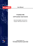
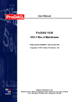
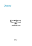
Figure 1 - ProDAQ 5720 Signal Conditioning Carrier with
ProDAQ 5821 RTD Signal Conditioning Card
The ProDAQ 5821 card is designed to work with the ProDAQ 3416 16-ch, 24-bit Sigma-Delta ADC
function card installed in one of the ProDAQ function card carriers for VXI or LXI systems. The
connection between the ADC function card and the signal conditioning card is done via a standard
ProDAQ 8010 SCSI-style data I/O cable. It carries the analog signals as well as the control signal
for the conditioning card.
The control of the signal conditioning card is done via an additional VXIplug&play driver, which
links to the standard ProDAQ 3416 driver dynamically. In this way, drivers for different signal
conditioning cards can be used at the same time with the ProDAQ 3416 driver.
1.1.1. ProDAQ 5720 Signal Conditioning Carrier
The ProDAQ 5720 can host up to two signal conditioning cards of the 5820 Series. It provides
power and cooling to the cards but provides no functionality of its own. It is designed to be
mounted in a standard 19” rack.
1.2. Features
The ProDAQ 5821 RTD Signal Conditioning Card provides excitation current, compensation
modes, gain etc for resistive type sensors such as:
Resistance Temperature Detectors (RTD)
A RTD sensing element consists of a wire coil or deposited film of pure metal. The element's
resistance increases with temperature in a known and repeatable manner. RTD's exhibit
excellent accuracy over a wide temperature range and represent the fastest growing
segment among industrial temperature sensors. Their advantages include a large
Page 9 of 94
Copyright, © 2013 Bustec Production Ltd.
5821-XX-UM
ProDAQ 5821 RTD Signal Conditioning Card User Manual
temperature range (typically -260 to 850°C), a low drift per year (ordinary RTD's typically drift
less than 0.1°C/year), a good linearity (better than thermocouples) and an industrial
standardization.
Thermistors
Thermistors are thermally sensitive resistors whose prime function is to exhibit a large,
predictable and precise change in electrical resistance when subjected to a corresponding
change in body temperature. Negative Temperature Coefficient (NTC) thermistors exhibit a
decrease in electrical resistance when subjected to an increase in body temperature and
Positive Temperature Coefficient (PTC) thermistors exhibit an increase in electrical
resistance when subjected to an increase in body temperature. Because of their very
predictable characteristics and their excellent long term stability, thermistors are generally
accepted to be the most advantageous sensor for many applications including temperature
measurement and control. Thermistors typically achieve a high precision within a limited
temperature range, typically −90 °C to 130 °C.
Cryogenic Diodes
Diode temperature sensors are based on the fact that the voltage drop across a forward
biased PN junction is a function of temperature. This voltage drop is determined by the
nature of the semiconductor. Diodes are usable from 1.4 Kelvin to 325 Kelvin, but are more
frequently used at 4.2 Kelvin and above. This temperature range can be covered by a single
device. Because diodes follow a standard calibration curve with reasonable accuracy, and
because a single device can cover this broad temperature range, diodes are widely used in
instrumentation and control systems for helium liquefiers, cryogenic distribution systems and
similar equipment. (Cryogenic diodes are supported only by the -BB version of the ProDAQ
5821)
With resistive devices, the lead wire resistance directly affects its accuracy. The error can be quite
large, depending on the lead wire resistance. The ProDAQ 5821 supports different types of
connection schemes for the sensors to compensate for the lead wire resistance.
2-wire
One lead wire is connected to each lead of the sensor. This arrangement is suitable for uses
where the lead wire resistance may be considered as a constant in the circuit; where
changes in the lead wire resistance due to ambient temperature changes can be ignored or
where the lead resistance is a fraction of the sensor resistance.
3-wire
This is the most common of RTD configurations. One lead wire is connected to one lead of
the element and two lead wires are connected to the other lead. A special built-in
compensation circuit “adds” the fourth wire (ProDAQ 5821-Bx only), providing a precision
comparable to the 4-wire compensation mode while allowing for less expensive cabling.
4-wire
The most accurate of the RTD configurations, this element uses two wires for each lead of
the sensor. By measuring the voltage directly at the sensor, compensation is made for the
resistance in each lead wire, allowing for a highly-accurate temperature measurement.
Copyright, 2013 Bustec Production Ltd.
Page 10 of 94
ProDAQ 5821 RTD Signal Conditioning Card User Manual
5821-XX-UM
2. Getting Started
The ProDAQ 5820 series signal conditioning cards are factory mounted into the ProDAQ 5720
carrier. There are no customer serviceable parts inside the ProDAQ 5720.
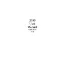
2.1. Mounting the ProDAQ 5720 into a 19” rack
The ProDAQ 5720 comes with two mounting brackets for standard 19” racks. To support different
cabling options, these mounting brackets can be attached to the ProDAQ 5720 in four different
ways:
Figure 2 - ProDAQ 5720 Front Rack-mount Options
Figure 3 - ProDAQ 5720 Rear Rack-mount Options
The ProDAQ 5720 carrier power supply accepts 115V/230V AC at 47-63Hz via a standard IEC inlet
on the rear.
Page 11 of 94
Copyright, © 2013 Bustec Production Ltd.
5821-XX-UM
ProDAQ 5821 RTD Signal Conditioning Card User Manual
Main Power
Switch
IEC
Inlet
Figure 4 - ProDAQ 5720 Rear View
2.2. Connecting to a ProDAQ 3416 ADC Function Card
For the connection between the ProDAQ 5821 Signal Conditioning Card and a ProDAQ 3416 ADC
Function Card a standard ProDAQ 8010-Bx series data I/O cable is used. The ProDAQ 5821 is
equipped with a standard 50-pin SCSI connector on its rear panel to attach the cable to.
Copyright, 2013 Bustec Production Ltd.
Page 12 of 94
ProDAQ 5821 RTD Signal Conditioning Card User Manual
5821-XX-UM
2.3. Connecting your Sensors
The ProDAQ 5821 uses 4-pole, 3.5mm pitch pluggable terminal block style connectors for the
sensor connection (Weidmüller BL 3.5/04/180F SN BK, P/N 1615800000). Lead wires of sizes
between 28 AWG and 14 AWG (0.2 mm2 to 1.5 mm2) can be directly inserted into the plug and are
secured by a clamping yoke screw system.
Figure 5 - Sensor Connector
Once plugged in, the connector can be secured by two screws to the socket.
Screwdriver
0.4mm x 2.5mm
Figure 6 - Wire and Plug Assembly
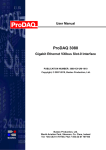
Each connector has four positions for connecting excitation and sensing leads dependent on the
chosen configuration.
I- S- S+ I+
Sense
Excitation
Figure 7 Connector Pin-out
Page 13 of 94
Copyright, © 2013 Bustec Production Ltd.
5821-XX-UM
ProDAQ 5821 RTD Signal Conditioning Card User Manual
The ProDAQ 5821 comes in different versions. Only the -Bx versions are equipped internally with
relays to make necessary connections, for example between I+ and S+ in 2-wire mode; the -Ax
versions do not support the configuration of the channels for different connection modes by
software.
2.3.1. 2-Wire Configuration
ProDAQ 5821-Ax versions
The ProDAQ 5821-Ax versions do not support the channel configuration for different sensor
connections. It is required instead that the wiring of the input connector is made accordingly. For a
2-wire configuration, this requires to add shorting links on the input connector between I+/S+ and
S-/I- as shown in Figure 8 .
Sensor
I+
S+
SI-
Figure 8 - ProDAQ 5821-Ax 2-wire sensor connection
ProDAQ 5821-Bx versions
The ProDAQ 5821-Bx versions support the channel configuration for the different sensor
connections internally. To connect to your sensor in a 2-wire configuration, simply attach the lead
wires to the excitation signal contacts of the plug (I+/I-). The connection to the sensing inputs is
made internally in the ProDAQ 5821 when configuring the particular channel for 2-wire mode via
the driver functions. No external shortening links are necessary between I+/S+ and S-/I-.
Sensor
I+
S+
SI-
Figure 9 - ProDAQ 5821-Bx 2-wire sensor connection
2.3.2. 3-Wire Configuration
ProDAQ 5821-Bx versions only
To connect a sensor using 3 wires, connect the lead wires to the excitation contacts and
additionally the negative sense contact (S-) of the plug. The compensation for the missing fourth
wire is automatically activated when configuring the particular channel for 3-wire mode via the
driver functions.
Copyright, 2013 Bustec Production Ltd.
Page 14 of 94
ProDAQ 5821 RTD Signal Conditioning Card User Manual
5821-XX-UM
Sensor
I+
S+
SI-
Figure 10 - ProDAQ 5821-Bx 3-wire sensor connection
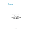
2.3.3. 4-Wire Configuration
For the 4-wire configuration separate sense and excitation wires need to be connected to the
sensor. This configuration yields the highest measurement accuracy.
Sensor
I+
S+
SI-
Figure 11 - 4-wire sensor connection
Page 15 of 94
Copyright, © 2013 Bustec Production Ltd.
5821-XX-UM
ProDAQ 5821 RTD Signal Conditioning Card User Manual
(This page was intenionelly left blank)
Copyright, 2013 Bustec Production Ltd.
Page 16 of 94
ProDAQ 5821 RTD Signal Conditioning Card User Manual
5821-XX-UM
3. The ProDAQ 5821 Soft Front Panel
The purpose of soft front panel application is to demonstrate the instrument’s abilities. The 5821
SFP connects to a 5821 via its control 3416. After the start of the soft front panel application, the
user has the choice to either enter the address information (VISA resource specification and
function card number) of the function card the soft front panel application shall connect to or else to
use the built-in “Auto Find” functionality in order to discover accessible ProDAQ 3416/5821 cards.
Figure 12 – Function Card Selection
Please note that the “Auto Find” find functionality will only inspect network resources that are
known to the VISA library to avoid unwanted accesses of network resources that might be
unintentionally reachable via the local network. For VXIbus resources, running the VISA resource
manager prior to running the soft front panel application is necessary for both the “Auto Find”
functionality to work and in general the access to the function card to be possible.
If “Auto Find” is selected and there are multiple ProDAQ 3416/5821 cards, the user will be
presented with a dialog box showing all available ProDAQ 3416 cards, allowing the selection of one
function card to connect to. It is important that the user choose a 3416 card that has a 5821
connected to it, otherwise an initialization error will occur. The soft front panel is not designed to
handle more than one function card and signal conditioning card at a time. If there is only one
function card / signal conditioning card available, the dialog box will not appear and the soft front
panel application will automatically establish communication to this instrument. If no ProDAQ
3416/5821 is available in your system, the soft front panel application can be run in demo mode,
allowing operation of all controls, as if connected to an instrument.
If “Enter Address” is selected, the user is presented with a dialog box that allows entering the VISA
resource string and the 3416 function card number directly, as shown in Figure 13.
Figure 13 – Entering Function Card Address
The resource string and range of function card numbers differ depending on the ProDAQ
Motherboard or Carrier that the ProDAQ 3416 is installed on. Please refer to the
motherboard/carrier user manual for more information.
After initializing the ProDAQ 3416 function card and ProDAQ 5821 signal conditioning card, during
which a splash screen is displayed, the soft front panel window shown in Figure 14 will appear.
Page 17 of 94
Copyright, © 2013 Bustec Production Ltd.
5821-XX-UM
ProDAQ 5821 RTD Signal Conditioning Card User Manual
Figure 14 – 5821 SFP Initial Start Up Screen
The soft front panel has separate graphical displays for the three different types of measurement
possible using the ProDAQ 5821, namely Voltage, Resistance and Temperature. Depending on the
channel configuration, the graph for the channel will be shown in the related graphical display.
Thus, all channels set to Voltage will be grouped together in the Voltage Waveform graphical
display and similarly for Resistance and Temperature. Only channels that are ‘Enabled’ will be
displayed.
After startup, only the graphical display for the temperature display is visible, as by default only
channel one, which is set for PT-100 measurement, is enabled. Using the buttons to the right of the
dividers, you can hide/unhide each of the displays. Clicking a down arrow will open a display and
the arrow will change to an up arrow. Clicking an up arrow will close a display and the arrow will
change to a down arrow.
Figure 15 – 5821 SFP Start Up Screen Drop Down Arrows
3.1. Channel Configuration
To configure the channels, select the “Channel Configuration” button on the right of the soft front
panel. This will open up a dialog box, allowing the operator to set the configuration for each
channel as shown in Figure 16. By default, channel 1 is enabled and the sensor type set to PT100.
Copyright, 2013 Bustec Production Ltd.
Page 18 of 94
ProDAQ 5821 RTD Signal Conditioning Card User Manual
5821-XX-UM
Figure 16 – 5821 Channel Configuration Dialog
All other channels are disabled. To enable or disable a channel use the drop-down box located on
the top left of the configuration channel dialog box, as shown in Figure 17.
Figure 17 – 5821 SFP Enable and Disable Channels
The control of each channel is separated using tabs. To control channel 10, for example, it is
necessary to click the ‘Ch 10’ tab. Each tab is functionally identical. The controls in each tab are
grouped in three group boxes, a ‘Configuration’ group, a ‘Calibration’ group and a ‘Status’ group.
The controls in the ‘Configuration’ group, shown in Figure 18, allow the operator to choose the
sensor type, the sensor configuration mode, the measurement range and, for RTD and Resistance
measurements, the ability to turn the excitation current on and off. Settings take place immediately
after a change has been selected. It is also possible to apply the channel configuration settings to
all other channels that have been enabled.
Figure 18 – 5821 SFP Configuration Group
The possible sensor types available are Temperature (PT-100, PT-500 and PT-1000 RTDs),
Resistive and Voltage type sensors. A drop-down box, shown in Figure 19, allows the operator to
select the type of sensor being used.
Page 19 of 94
Copyright, © 2013 Bustec Production Ltd.
5821-XX-UM
ProDAQ 5821 RTD Signal Conditioning Card User Manual
Figure 19 – 5821 SFP Sensor Selection
Depending upon the version of the 5821, both the temperature and resistive sensors may be
operated in three different modes, namely 2-wire, 3-wire and 4-wire mode. These modes are
described in section Error! Reference source not found.. Note that the 5821-Ax only has 4-wire
mode available.
Figure 20 – 5821 SFP Mode Selection, RTD or Resistor
Both the temperature and resistive sensors generally require an excitation current. This current
may be switched on or off. For the 5821-xA the current is nominally 500µA. For the 5821-BB a
second current level of nominally 10µA is also available. During calibration the set current is
calibrated and used during Data Acquisition (DA). The current is also adjusted in order to be as
close as possible to the nominal value. This feature is useful for cryogenic diodes, for example,
where the diode output voltage over temperature is normally specified for a given current level,
generally 10µA.
If the selected sensor type is ‘Voltage’ then two modes of operation are possible, namely
Differential Voltage and Single Ended Voltage, as shown in Figure 21. A differential voltage signal
has three outputs, namely a ground reference and two signal lines that are in opposite polarity
(balanced) around the ground reference. In this case the I- pin of the connector should be used as
the ground reference and S+/S- use as the signal inputs. A single-ended voltage signal has two
outputs, namely a ground reference and a signal line. In this case S+ should be used as the signal
input and S- as the ground reference input. Note how excitation current is switched off for voltage
sensors.
Each sensor type has a number of Measurement Ranges associated with it. In order to ensure the
highest measurement accuracy it is important that the operator selects the appropriate range. For
the PT-100, PT-500 and PT-1000 the measurement units are °C and all associated waveforms will
display on the Temperature graph.
Copyright, 2013 Bustec Production Ltd.
Page 20 of 94
ProDAQ 5821 RTD Signal Conditioning Card User Manual
5821-XX-UM
Figure 21 – 5821 SFP Mode Selection, Voltage
As shown in Figure 22, for the PT-100 there are four available measurement ranges, < -80°C, <
100°C, < 500°C and < 850°C. The PT-500 and PT-1000 sensors have different ranges, namely < 100°C, < 0°C, < 300°C and < 850°C.
Figure 22 – 5821 SFP Measurement Range Selection, Temperature Sensors
If the measured temperature is greater than the chosen measurement range then the red Error
LED will light. In Figure 23 a 100Ω resistor is connected to channel 1, simulating a PT-100
operating at 0°C. The maximum temperature of the selected measurement range is -80°C and thus
the temperature is outside the range. Hence the Error LED lights.
Figure 23 – 5821 SFP Measurement Range Selection too Low, PT-100
Page 21 of 94
Copyright, © 2013 Bustec Production Ltd.
5821-XX-UM
ProDAQ 5821 RTD Signal Conditioning Card User Manual
If the ‘Resistance’ sensor type with 500µA of current is chosen then nine resistance ranges are
available, varying from < 70Ω up to < 20kΩ. Again, as with Temperature Sensors, if the measured
resistance is greater than the chosen measurement range then the red Error LED will light.
Figure 24 – 5821 SFP Measurement Range Selection, Resistive Sensors, 500µA current
If the current setting is 10µA (-BB only) then the resistive ranges vary from < 4kΩ to < 1MΩ, as
shown in Figure 25.
Figure 25 – 5821 SFP Measurement Range Selection, Resistive Sensors, 10µA current
For Voltage sensors the measurement ranges vary from ±35mV to ±10V.
Figure 26 – 5821 SFP Measurement Range Selection, Voltage Sensors
3.2. Channel Calibration
Copyright, 2013 Bustec Production Ltd.
Page 22 of 94
ProDAQ 5821 RTD Signal Conditioning Card User Manual
5821-XX-UM
The 3416/5821 system has factory default calibration values which allow an operator to make
extremely accurate measurements without performing further calibration. However, for the highest
accuracy, it is recommended that an ‘online’ calibration be made after the system has warmed-up
sufficiently (30 minutes minimum). To make an online calibration the operator simply has to click
the button ‘Calibrate Channel’ as shown in Figure 27. Alternatively all enabled channels may be
calibrated sequentially using the ‘Calibrate All Enabled Channels’ button. Note that this might take
some time if a lot of channels are enabled.
Figure 27 – 5821 SFP Calibration Frame
An online calibration makes a calibration at the configuration settings chosen by the operator.
Furthermore, in the case of temperature and resistive sensors it automatically calibrates current by
using the 3416 to measure the voltage across the internal precision resistor used for setting the
excitation current. This high precision resistor has a tolerance of 0.01% and a temperature drift of
just 1ppm/°C.
Calibration may be made with or without a sensor connected. If no sensor is connected the
software detects this fact and automatically grounds the output of the current source in order to
allow current calibration to be made. If a sensor is detected then the current flowing through that
sensor is calibrated and adjusted to the set value (500µA or 10µA).
The calibration process involves three steps, all of which are invisible to the user. First a voltage
calibration of the signal path is made, then a voltage calibration of the current path is made and
finally a calibration of the excitation current is made. In this way the highest possible accuracy is
achieved.
3.3. Channel Status
Figure 28 shows a screenshot of the Channel Status group box. It contains two LED controls and a
Test Wire button. The Excitation Current Status LED indicates the status of the excitation current.
If the excitation current is off then the Excitation Current Status LED will be off (grey, as shown in
Figure 28).
Figure 28 – 5821 SFP Channel Status
If the excitation current is turned on and is flowing correctly then the Excitation Current Status LED
will be green, as shown in Figure 29.
Page 23 of 94
Copyright, © 2013 Bustec Production Ltd.
5821-XX-UM
ProDAQ 5821 RTD Signal Conditioning Card User Manual
Figure 29 – 5821 SFP Excitation Current Status LED green
If the excitation current is turned on but is not flowing correctly then the Excitation Current Status
LED will be red, as shown in Figure 30. Note that the error LED has not indicated an error. Thus,
the operator needs to check that the status of both LEDs is as expected.
Figure 30 – 5821 SFP Excitation Current Status LED red
The Error LED is normally grey but will go red if a fault is detected. An example of a fault is signal
over-range detection. If this LED is red it is recommended firstly to check channel configuration
and secondly to test for broken wires using the Test Wire button. Note that the error LED operates
using polling and thus it might several seconds before the LED reacts.
The Test Wire button will check whether any wires from the sensor that are connected to the
channel are broken. It is disabled if excitation current is off and is not available for Voltage sensors.
The number of wires checked depends on the chosen mode, 4-wire, 3-wire or 2-wire. In 4-wire
mode all four wires are checked, in 3-wire mode the S+ input is not checked and in 2-wire mode
only I+ and I- are checked.
Testing for broken wires involves a two step process. The first step involves checking the I+ and Iwires. If these are determined to be ok then S+ and S- are checked and it can be determined
whether S+, S- or both are broken. If a wire is ok a green message indicates this while a broken
wire has a red message.
If I+ or I- are broken it is not possible to determine which and thus a yellow message is displayed,
indicating that one of the wires or possibly both are broken and thus they should be checked. The
signal wires are shown in blue with status unknown. After fixing these wires the operator should run
Test Wires again to confirm that all wires are now ok.
Figure 31 to Figure 35 show various simulated broken wire conditions.
Copyright, 2013 Bustec Production Ltd.
Page 24 of 94
ProDAQ 5821 RTD Signal Conditioning Card User Manual
5821-XX-UM
Figure 31 – 5821 4-Wire Mode All Wires OK
Figure 32 – 5821 4-Wire Mode Broken I- Wire
Figure 33 – 5821 4-Wire Mode Broken S+ Wire
Figure 34 – 5821 3-Wire Mode No S+ Wire so all wires OK
Figure 35 – 5821 2-Wire Mode No S+, S- Wires so all wires OK
3.4. Making a Measurement
This section describes the process of making a measurement, in order to guide the operator more
clearly. Several sensor types will be considered, a PT-100 in 4-wire and 3-wire mode, a PT-1000, a
PT-500, a precision high resistance sensor and a voltage sensor.
During these tests a 3416-AA, mounted in a 6100-AA, was connected to a 5821-BA via a 2m SCSI
cable. The whole system was suitably warmed up.
Page 25 of 94
Copyright, © 2013 Bustec Production Ltd.
5821-XX-UM
ProDAQ 5821 RTD Signal Conditioning Card User Manual
3.4.1. PT-100 operating at 0°C
A 100Ω 0.005% 1ppm resistor was connected to channel 14 via a 30m 24AWG multi-core cable
and connected in 4-wire mode. Using an 8.5digit DMM operating in 4-wire mode the resistance of
the load was previously confirmed to be 100.007Ω, slightly outside the ±5mΩ specification quoted
by the manufacturer. A resistance of 100.007Ω equates to a temperature of 0.018°C for the PT100 sensor.
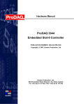
Channel 14 was enabled and the sensor type set to PT-100, with 4-wire mode. The current was set
to 500µA. As the expected temperature was 0.018°C, the temperature range was set to < 100°C
(the maximum recommended operating temperature for this range) in order to maximize the
measurement accuracy. Figure 36 shows the configuration of channel 14. Note how the Excitation
Current Status LED is green, indicating that current is on and flowing.
Figure 36 – Configuration of Channel 14
An online calibration of channel 14 was made and the channel configuration dialog closed. In the
main panel the sample rate was set to 1ksps with 1000 samples. The test duration in this case is
thus 1s. It is of course possible to sample at different sample rates and varying numbers of
samples.
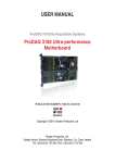
The green single DA button was clicked and the 1000 measurement values shown in Figure 37
captured.
Copyright, 2013 Bustec Production Ltd.
Page 26 of 94
ProDAQ 5821 RTD Signal Conditioning Card User Manual
5821-XX-UM
Figure 37 –Channel 14 Temperature Waveform
Clicking on the ‘Statistics’ button shows that the mean value of this waveform is 0.066°C,
compared to the ideal value of 0.018°C for a 100.007Ω resistor, a typical error of 0.048°C. The
peak to peak range of the measured values is about 0.04°C.
Figure 38 –Channel 14 Mean Measured Temperature
3.4.2. PT-100 operating at 0°C in 3-Wire Mode
A 100Ω 0.005% 1ppm resistor was connected to channel 1 via a 30m 24AWG multi-core cable and
connected in 3-wire mode (the S+ wire was disconnected). Using an 8.5digit DMM operating in 4wire mode the resistance of the load was previously confirmed to be 100.007Ω, slightly outside the
±5mΩ specification quoted by the manufacturer. A resistance of 100.007Ω equates to a
temperature of 0.018°C for the PT-100 sensor.
Figure 39 shows the initial screen after the ‘Channel Configuration’ button is clicked. The Status
LEDs show that the excitation current is off and also that there is an error detected.
Page 27 of 94
Copyright, © 2013 Bustec Production Ltd.
5821-XX-UM
ProDAQ 5821 RTD Signal Conditioning Card User Manual
Figure 39 – Configuration of Channel 1 Initial Screen
Figure 40 shows the LED status after turning on the 500µA excitation current. The current is
flowing correctly but the error flag is still red. The measurement range is set correctly to < 100°C.
Note however that the chosen Mode is 4-Wire while the sensor is connected up as 3-Wire.
Figure 40 – Configuration of Channel 1 Excitation Current On
Changing the mode to 3-Wire eliminates the error, as shown in Figure 41.
Copyright, 2013 Bustec Production Ltd.
Page 28 of 94
ProDAQ 5821 RTD Signal Conditioning Card User Manual
5821-XX-UM
Figure 41 – Configuration of Channel 1 3-Wire Mode Selected
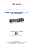
After calibration a measurement was made with 1000 samples at 1ksps. This is shown in Figure
42. The mean value, given in Figure 43, is -0.12°C compared to the theoretical value of 0.018°C, a
difference of 0.138°C.
Figure 42 – Measurement of Channel 1 PT100 sensor 3-Wire Mode
Page 29 of 94
Copyright, © 2013 Bustec Production Ltd.
5821-XX-UM
ProDAQ 5821 RTD Signal Conditioning Card User Manual
Figure 43 – Statistics Mean of Measurement of Channel 1 PT100 sensor 3-Wire Mode
In order to demonstrate how effective the 3-Wire compensation circuit is channel 1 was configured
for 4-Wire mode but only 3 wires were connected to the 100Ω resistor. In order for the channel to
function correctly S+ and I+ were shorted at the connector. A measurement was then made using
the same measurement range.
Figure 44 shows the result. The error without using 3-Wire compensation is now about 6.5°C,
about 50 times worse than using the compensation. Obviously this figure would vary with sensor
resistance, cable length and size.
Figure 44 – Measurement of Channel 1 PT100 4-Wire Mode, S+ and I+ Shorted Externally
Copyright, 2013 Bustec Production Ltd.
Page 30 of 94
ProDAQ 5821 RTD Signal Conditioning Card User Manual
5821-XX-UM
3.4.3. Measuring a 1.25kΩ Resistor as a PT-1000 and PT-500
A 1.25kΩ 0.01% 1ppm resistor was connected to channel 9 via a 30m 24AWG multi-core cable
and connected in 4-wire mode. Using an 8.5digit DMM operating in 4-wire mode the resistance of
the load was previously confirmed to be 1249.95Ω, well within the ±125mΩ specification quoted by
the manufacturer. A resistance of 1249.95Ω equates to a temperature of 64.57°C for the PT-1000
sensor and 408.42°C for a PT-500.
Channel 9 was enabled and the sensor type set to PT-1000, with 4-wire mode. The current was set
to 500µA. As the expected temperature was 64.57°C, the temperature range was set to < 300°C
(the maximum recommended operating temperature for this range) in order to maximize the
measurement accuracy. A calibration was then made and results taken.
Figure 45 shows the measured waveform and Figure 46 gives a mean value of 64.58°C, a
difference of just 0.01°C from the theoretical value. It can be seen that the peak-peak variation
around this mean is less than ±0.01°C.
Figure 45 – Measurement of Channel 9 sensor PT-1000
Figure 46 – Statistics Mean of Measurement of Channel 9 sensor, PT-1000
Page 31 of 94
Copyright, © 2013 Bustec Production Ltd.
5821-XX-UM
ProDAQ 5821 RTD Signal Conditioning Card User Manual
Channel 9 was then set to PT-500, with 4-wire mode. As the expected temperature was 408.42°C,
the temperature range was changed to < 850°C (the maximum recommended operating
temperature for this range) in order to maximize the measurement accuracy. A calibration was then
made and results taken. Note that a calibration was made because the measurement range was
changed.
Figure 47 shows the measured waveform and Figure 48 gives a mean value of 408.48°C,
compared to the theoretical value of 408.42°C. The difference is just 0.06°C. It may be seen that
the peak-peak variation around this mean is about ±0.015°C.
Figure 47 – Measurement of Channel 9 sensor PT-500
Figure 48 – Statistics Mean of Measurement of Channel 9 sensor, PT-500
Copyright, 2013 Bustec Production Ltd.
Page 32 of 94
ProDAQ 5821 RTD Signal Conditioning Card User Manual
5821-XX-UM
3.4.4. Measuring a 5kΩ Resistor
A 5kΩ 0.01% 1ppm resistor was connected to channel 8 via a 50m 24AWG multi-core cable and
connected in 4-wire mode. Using an 8.5digit DMM operating in 4-wire mode the resistance of the
load was previously confirmed to be 4999.61Ω, just inside the ±0.5Ω specification quoted by the
manufacturer. Figure 49 shows the final set-up.
Figure 49 – Configuration of Channel 8 Resistance 4-Wire Mode Selected
Channel 8 was calibrated and the configuration dialog box closed. A test was made using 50
samples at 100Hz sampling rate. Figure 50 shows the result. The 50 measurements vary from
4999.64Ω to 4999.73Ω. Figure 51 shows that the mean resistance value is 4999.69Ω, a difference
of just 80mΩ or just 0.0016% from the value calibrated using an 8.5 digit DMM. The peak-peak
variation around the mean is about ±40mΩ or ±0.0008%.
Page 33 of 94
Copyright, © 2013 Bustec Production Ltd.
5821-XX-UM
ProDAQ 5821 RTD Signal Conditioning Card User Manual
Figure 50 – Measurement of Channel 8 sensor 5kΩ Resistance
Figure 51 – Statistics Mean of Measurement of Channel 8 sensor, 5kΩ Resistance
Copyright, 2013 Bustec Production Ltd.
Page 34 of 94
ProDAQ 5821 RTD Signal Conditioning Card User Manual
5821-XX-UM
3.4.5. Measuring a Voltage Signal
A 100mV DC voltage was set-up and measured using a calibrated 8.5 digit DMM. The measured
value was 100.771mV. Chanel 7 was set-up for voltage as shown in Figure 52 and calibrated
online. The measurement range was ±0.14V.
Figure 52 – Configuration of Channel 8 Voltage Input
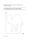
Figure 53 shows the result of the measurement while Figure 54 shows that the mean measured
voltage was 100.766mV, a difference of 5µV from the mean value measured by the 8.5 digit DMM.
The peak-peak variation around the mean was about 45µV or 7µVRMS. An error of 5µV on a
±100mV range is 0.005% Full-Scale.
Page 35 of 94
Copyright, © 2013 Bustec Production Ltd.
5821-XX-UM
ProDAQ 5821 RTD Signal Conditioning Card User Manual
Figure 53 – Measurement of Channel 8 Voltage Input
Figure 54 – Statistics Mean of Measurement of Channel 8 Voltage Input
Copyright, 2013 Bustec Production Ltd.
Page 36 of 94
ProDAQ 5821 RTD Signal Conditioning Card User Manual
5821-XX-UM
4. Programming the ProDAQ 5821
This chapter shows how to program the ProDAQ 5821 signal conditioning card using the
VXIplug&play driver. Complete examples can be found in the “Examples” subdirectory of the driver.
All functions are explained in detail in the help file coming with the driver.
4.1. VXIplug&play Driver Organization
The VXIplug&play driver is organized in a hierarchical manner to allow the user to quickly choose
the function calls to solve the task at hand without being confronted with unnecessary details.
Besides the standard connection/disconnection and utility functions it contains different levels of
functionality which provide single functions or sets of functions to solve a particular data acquisition
task:
Function Tree Layout:
ProDAQ 5821 RTD Signal Conditioning Card
Initialization
Hardware Configuration
Set Channel Configuration
Get Channel Configuration
Calibration Functions
Signal Path Calibration
Excitation Current Calibration
bu5821_init
bu5821_setChanConfig
bu5821_getChanConfig
bu5821_pgaCalibration
bu5821_excCalibration
Low-level Access
…
Utility Functions
Read Temperature
Reset
Error Message
Device Serial Number
Revision Query
Get Function Card Last Error
Check Broken Wire
Set Conversion
Close
bu5821_readTemperature
bu5821_reset
bu5821_error_message
bu5821_serialNumber
bu5821_revision_query
bu5821_getFCLastError
bu5821_brokenWireDetect
bu5821_bu5821_setConversion
bu5821_close
Figure 55 – VXIplug&play Driver Organization
The section Hardware Configuration contains high-level functions to configure the card. The
section Calibration Functions contains high-level functions that can be used to calibrate the
ProDAQ 3416 and ProDAQ 5821. The section Utility Functions contains utility functions that can
be used together with the high-level functions.
The section Low-level Access contains functions that directly change settings on a register level
and are used by the higher level functions to implement their functionality. Using them directly in
combination with the higher level functions might interfere with the functionality implemented and
should be avoided. In general the usage of the low-level functions will require an intimate
knowledge of the ProDAQ 5821 hardware as well as the hardware of the ProDAQ 3416 and the
respective function card carrier. Before you attempt to implement your data acquisition or test
application using them, it is recommended to study their usage in the higher level functions in the
driver sources and/or contact Bustec for support.
The following paragraphs will explain the usage of the high level functions.
Page 37 of 94
Copyright, © 2013 Bustec Production Ltd.
5821-XX-UM
ProDAQ 5821 RTD Signal Conditioning Card User Manual
4.2. Connecting to the Function Card and Signal Conditioning Card
The ProDAQ 5821 driver utilizes the ProDAQ 3416 driver to access the signal conditioning card.
Therefore first the ProDAQ 3416 driver need to be initialized and connected to the correct function
card (the one connect via cable to the ProDAQ 5821) before the ProDAQ 5821 driver can be
initialized.
To initialize the ProDAQ 3416 driver and connect to the ProDAQ motherboard or function card
carrier, the standard VXIplug&play initialization function bu3416_init() is used (see Figure
56,). (Please refer to the VXIplug&play standard VPP-4.3, section 4.3 for a detailed description of
the address string.) After initializing the driver and connecting to the motherboard or carrier, the
driver must be told which one of the function cards to work with. This is done by the function
bu3416_fcSelect(). It takes as an argument the session established via the function
bu3416_init(), the function card number and a boolean value specifying whether to reset the
selected function card (see Figure 56, ).
#include <visa.h>
#include <bu3416.h>
#include <bu5821.h>
main (int argc, char **argv)
{
ViStatus status;
ViSession session_3416;
ViSession session_5821;
ViChar descr[256];
#ifndef USE_PARAMINIT
/* connect to a ProDAQ motherboard in a VXIbus system */
if ((status = bu3416_init(“VXI0::2::INSTR”, VI_TRUE, VI_TRUE, &session_3416)) != VI_SUCCESS)
{
viStatusDesc (session_3416, status, descr);
printf (“Error: bu3416_init() failed due to %s\n”, descr);
return -1;
}
/* use function card in position/slot 1 */
if ((status = bu3416_fcSelect(session_3416, 1, VI_TRUE)) != VI_SUCCESS)
{
viStatusDesc (session_3416, status, descr);
printf (“Error: bu3416_fcSelect failed due to %s\n”, descr);
return -1;
}
#else
/* OR: connect to a 3416 in position 1 in a LXI function card carrier */
if ((status = bu3416_paramInit(“TCPIP::192.168.168.63::INSTR”,
1, VI_TRUE, VI_TRUE, &session_3416)) != VI_SUCCESS)
{
viStatusDesc (rm_session, status, descr);
printf (“Error: bu3416_paramInit() failed due to %s\n”, descr);
return -1;
}
#endif
/* connect to the 5821 controled by the 3416 */
if ((status = bu5821_init(session_3416, VI_TRUE, VI_TRUE, &session_5821)) != VI_SUCCESS)
{
viStatusDesc (session_5821, status, descr);
printf (“Error: bu5821_init() failed due to %s\n”, descr);
return -1;
}
/* ... */
Figure 56 - Connecting to The ProDAQ 3416 and ProDAQ 5821
For your convenience, the driver contains a new function called bu3416_paramInit(), which
combines the functionality of the bu3416_init() and bu3416_fcSelect() functions by extending
Copyright, 2013 Bustec Production Ltd.
Page 38 of 94
ProDAQ 5821 RTD Signal Conditioning Card User Manual
5821-XX-UM
the argument list of the standard initialization function with a parameter specifying the function card
number (see Figure 56,).
For the driver functions to work properly, you will either have to use the function
bu3416_paramInit() to open a session with the device, or you will have to call the function
bu3416_fcSelect()after calling the function bu3416_init() and before any other driver function
is called.
Now you can connect to the ProDAQ 5821 as well by using the function bu5821_init() with the
session handle to the ProDAQ 3416 returned by the functions bu3416_init()
or
bu3416_paramInit(). As with the ProDAQ 3416 init function you have the choice whether to
check the ID of the signal conditioning card to connect to as well as to reset the card (see Figure
56, ). The function returns a new session handle, which must be used with all ProDAQ 5821
driver functions
To close the driver sessions with the ProDAQ 5821 and the ProDAQ 3416, the standard
VXIplug&play functions bu5821_close() and bu3416_close() must be used, preferably in this
sequence.
NOTE
Please note that only code snippets are shown here in the manual. For the complete
example, refer to the ‘Examples’ folder in the drivers installation directory.
4.3. Hardware Configuration
To measure correctly, an application need to configure both cards, the ProDAQ 3416 as well as the
ProDAQ 5821.
4.3.1. ProDAQ 3416 Channel Configuration
The input multiplexer and gain stages on the ProDAQ 3416 function card are configured using the
function bu3416_setChanConfig(). It takes as arguments the session to the instrument, a channel
number, a selection for the input multiplexer and a value for the gain setting. The channel number
has to be an integer number in the range of 1...16 to select one of the channels or 0 for applying
the configuration to all channels. Predefined macros from the include file bu3416.h can be used
(bu3416_CHAN_1 to bu3416_CHAN_16 or bu3416_CHAN_ALL). The input multiplexer can be set to
either connect the channel’s input to the front panel connector or to the internal voltage reference
bus. The selection can be made by using an integer value of 0 (front panel connector) or 1 (voltage
reference bus) or again by using a macro predefined in bu3416.h (bu3416_CH_FP or
bu3416_CH_VREF). The gain can be set in steps of 1, 2, 5 between 1 and 2000 by either using valid
integer numbers (1, 2, 5, 10, 20, 50, 100, 200, 500, 1000, 2000) or by using the predefined macros
bu3416_GAIN_1 to bu3416_GAIN_2000 (for more information, refer to the ProDAQ 3416 User
Manual).
4.3.2. ProDAQ 5821 Channel Configuration
The ProDAQ 5821 allows to configure the channel for a connection mode (5821-Bx only) as well as
to configure its gain stage and excitation current via the driver function bu5821_setChanConfig().
It takes as an input the instrument session, a channel number, the selection of a mode (ignored for
5821-Ax versions), the gain and the selection of the excitation current. As for the ProDAQ 3416’s
bu3416_setChanConfig() function, the channel number has to be an integer number in the range
of 1...16 to select one of the channels or 0 for applying the configuration to all channels. Predefined
Page 39 of 94
Copyright, © 2013 Bustec Production Ltd.
5821-XX-UM
ProDAQ 5821 RTD Signal Conditioning Card User Manual
macros from the include file bu5821.h can be used for all the settings. The mode can be set for 2wire (bu5821_MODE_2_WIRE), 3-wire (bu5821_MODE_3_WIRE), 4-wire (bu5821_MODE_4_WIRE),
single-ended and differential voltage (bu5821_MODE_SE_VOLT, bu5821_MODE_DIFF_VOLT) and
other modes which can be used for calibration or test purposes (see chapter 5.1.24). The gain can
be set to values of 1/8th to 128 (1/8, 1/4, 1/2, 1, 2, 4, 8, 16, 32, 64, 128) by using the macros
bu5821_GAIN_1_8 to bu5821_GAIN_128. The excitation current can be switched off
(bu5821_CURRENT_OFF) or can be enables and set to 10 µA (bu5821_CURRENT_10, 5821-BB only)
or 500 µA (bu5821_CURRENT_500).
4.4. Calibration
The calibration of the ProDAQ 3416 and ProDAQ 5821 requires several steps, mainly because the
calibration of the excitation current requires first the complete signal path being calibrated for
accurate voltage measurements. Once the excitation current is calibrated, the ProDAQ 5821 can
be configured and calibrated for the desired mode of operation and measurement.
4.4.1. Excitation Current Calibration
To calibrate the excitation current, three steps are necessary. The first step is to calibrate the
ProDAQ 3416. The second step is to calibrate the signal path of the ProDAQ 5821 and the last
step then is to calibrate the excitation current.
For the best precision, the ProDAQ 3416 normally has to be calibrated for each gain separately.
But due to the design of the gain stage in the ProDAQ 5821, the optimal gain setting for the
ProDAQ 3416 when used together with the ProDAQ 5821 is a gain of 2 for all measurements.
Therefore the calibration of the ProDAQ 3416 only needs to be done once for this particular gain
setting.
The calibration is done by using the function bu3416_calibrateChannels() (see Error!
Reference source not found., ). This function takes as input a channel bit mask, the setting for
the gain the channel(s) shall be calibrated at and returns after a successful calibration the different
coefficients which will be applied by the driver. As these coefficients are not used here, VI_NULL is
passed in the example for those parameters, in which case the function ignores them.
Next the signal path of the ProDAQ 5821 needs to be configured and calibrated for a gain of 1 (see
Error! Reference source not found., & ).. This ensures the accurate measurements of
voltages within the correct range for the current calibration throughout the complete signal path
from the ProDAQ 5821 front-end to the ProDAQ 3416 ADC. This is done by the function
bu5821_pgaCalibration(). The function takes as parameters again a channel number
(bu5821_CHAN_1 to bu5821_CHAN_16) and a selection of the reference source and returns the
coefficients the driver will use.
To perform voltage calibration on the ProDAQ 5821, there are several options. If no voltage
reference is present in the system, the ProDAQ 5821 can only perform an offset calibration. In this
case you need to use the reference source selection bu5821_VREF_NO_VREF. If the controlling
ProDAQ 3416 is installed on a VXIbus motherboard or LXI function card carrier with a voltage
reference installed, so that this reference voltage is forwarded to the ProDAQ 5821, the source
selections bu5821_VREF_0V, bu5821_VREF_FROM_MASTER or bu5821_VREF_MASTER_POS can be
used. In case of bu5821_VREF_0V, again only an offset calibration is performed, but the ground
reference of the master is used. bu5821_VREF_FROM_MASTER performs a full calibration, while
bu5821_VREF_MASTER_POS only performs an offset calibration.
Another option to perform calibration is to use an external calibrator connected to the voltage
reference monitor connector on the ProDAQ 5821. In this case bu5821_VREF_CUSTOM must be
used and the exact voltage need to be specified as the fourth parameter for the function
Copyright, 2013 Bustec Production Ltd.
Page 40 of 94
ProDAQ 5821 RTD Signal Conditioning Card User Manual
5821-XX-UM
bu5821_pgaCalibration(). In the example (see Error! Reference source not found., )
bu5821_VREF_MASTER_POS is used to save time as the current calibration does not require to
measure negative values.
Figure 57 - Excitation Current Calibration
{
ViStatus status;
ViSession session_3416;
ViSession session_5821;
ViChar descr[256];
ViReal64 excitCurrent;
/* ..initialization as per Figure 56 */
/* configure channel one of the 3416 for gain 2, front panel connector input */
if ((status = bu3416_setChanConfig (session_3416, bu3416_CHAN_1,
bu3416_CH_FP, bu3416_GAIN_2, VI_FALSE)) < VI_SUCCESS)
{
bu3416_error_message (session_3416, status, descr);
printf (“Error: bu3416_setChanConfig() failed due to %s\n”, descr);
return -1;
}
/* Excitation Current Calibration */
/* Step 1: Calibrate the 3416 for GAIN 2 */
if ((status = bu3416_calibrateChannels (session_3416, 0x0001, bu3416_GAIN_2,
VI_NULL, VI_NULL, VI_NULL)) < VI_SUCCESS)
{
bu3416_error_message (session_3416, status, descr);
printf (“Error: bu3416_calibrateChannels() failed due to %s\n”, descr);
return -1;
}
/* configure 5821 channel 1 for gain 1 */
if ((status = bu5821_setChanConfig (session_5821, bu5821_CHAN_1,
bu5821_MODE_4_WIRE, bu5821_GAIN_1,
bu5821_CURRENT_500)) < VI_SUCCESS)
{
bu5821_error_message (session_5821, status, descr);
printf (“Error: bu5821_setChanConfig() failed due to %s\n”, descr);
return -1;
}
/* Excitation Current Calibration */
/* Step 2: Calibrate the signal path of the 5821 */
if ((status = bu5821_pgaCalibration (session_5821, bu5821_CHAN_1,
bu5821_VREF_MASTER_POS, 0.0, VI_NULL, VI_NULL)) < VI_SUCCESS)
{
bu5821_error_message (session_5821, status, descr);
printf (“Error: bu5821_pgaCalibration () failed due to %s\n”, descr);
return -1;
}
/* Excitation Current Calibration */
/* Step 3: Calibrate the 5821 current excitation */
if ((status = bu5821_excCalibration (session_5821, bu5821_CHAN_1, bu5821_CURRENT_500,
&excitCurrent, VI_NULL)) != VI_SUCCESS)
{
bu5821_error_message (session_5821, status, descr);
printf (“Error: bu5821_excCalibration() failed due to %s\n”, descr);
return -1;
}
/* ... */
}
Page 41 of 94
Copyright, © 2013 Bustec Production Ltd.
5821-XX-UM
ProDAQ 5821 RTD Signal Conditioning Card User Manual
Now the excitation current can be calibrated using the function bu5821_excCalibration(). This
function calibrates a particular channel for one of possible currents and returns the exact value of
the current measured (see Figure 57, ).
Note
The calibration coefficients or absolute current values the excitation functions
return are also stored in the driver and automatically applied.
4.4.2. Final Calibration
Once the excitation current is calibrated, the ProDAQ 5821 can be configured for the planned
measurement. If this measurement requires a different gain setting then the gain setting used
during the excitation current calibration, then, to reach the highest possible accuracy, the signal
path needs to be calibrated again for the new gain. In the example the ProDAQ 5821 is configured
for 3-wire mode and a gain of 64 to use a PT100 sensor and then the signal path is again
calibrated using the function bu5821_pgaCalibration() (see Figure 58, & ).
{
ViReal64 dblBuf[128];
/* initialization and excitation current calibration */
/* … */
/* configure the ProDAQ 5821 for 3-wire mode, gain 64, exc. current 500 uA */
if ((status = bu5821_setChanConfig (session_5821, bu5821_CHAN_1,
bu5821_MODE_3_WIRE, bu5821_GAIN_64,
bu5821_CURRENT_500)) < VI_SUCCESS)
{
bu5821_error_message (session_5821, status, descr);
printf (“Error: bu5821_setChanConfig() failed due to %s\n”, descr);
return -1;
}
/* Final Signal Path Calibration */
if ((status = bu5821_pgaCalibration (session_5821, bu5821_CHAN_1,
bu5821_VREF_MASTER_POS, 0.0, VI_NULL, VI_NULL)) < VI_SUCCESS)
{
bu5821_error_message (session_5821, status, descr);
printf (“Error: bu5821_pgaCalibration () failed due to %s\n”, descr);
return -1;
}
/* acquire 128 Samples at 1000 Samples/sec */
if((status = bu3416_acquireWaveform (session_3416, bu3416_CHAN_1, bu3416_CH_FP,
bu3416_GAIN_2, VI_FALSE, 1000.0, 128,
dblBuf, VI_NULL)) < VI_SUCCESS)
{
bu3416_error_message (session_3416, status, descr);
printf (“Error: bu3416_ acquireWaveform() failed due to %s\n”, descr);
return -1;
}
/* ... */
}
Figure 58 - Final Configuration, Calibration and Measurement
Copyright, 2013 Bustec Production Ltd.
Page 42 of 94
ProDAQ 5821 RTD Signal Conditioning Card User Manual
5821-XX-UM
4.5. Performing a Measurement
To perform measurements, the appropriate ProDAQ 3416 driver function must be used. In the
example the function bu3416_acquireWaveform() is used to acquire 128 Samples at speed of
1000 Samples/sec from channel 1 (see Figure 58, ). To do the same on multiple channels, the
function bu3416_acquireWaveforms() can be used. For continuous acquisition, functions like
bu3416_startAcquisition(), bu3416_stopAcquisition() etc must be used (for more
information, refer to the ProDAQ 3416 user manual and driver documentation).
The following table shows the ProDAQ 5821 configuration parameter to be used for the different
types of sensors and measurements calculated to reach the highest accuracy.
Sensor
PT100
PT500
PT1000
Resistance
Voltage
Range
< 850 °C
< 500 °C
< 100 °C
< -80 °C
< 850 °C
< 300 °C
< 0 °C
< -110 °C
< 850 °C
< 300 °C
< 0 °C
< -110 °C
20 kΩ
9 kΩ
4.5 kΩ
2.25 kΩ
1.12 kΩ
560 Ω
280 Ω
140 Ω
70 Ω
1 MΩ
450 kΩ
225 kΩ
112 kΩ
56 kΩ
28 kΩ
14 kΩ
7 kΩ
3.5 kΩ
±10 V
±4.5 V
±2.25 V
±1.12 V
±0.56 V
±0.28 V
±0.14 V
±0.07 V
±0.035V
Mode
Current
2-wire
3-wire
4-wire
500 µA
2-wire
3-wire
4-wire
500 µA
2-wire
3-wire
4-wire
500 µA
500 µA
2-wire
3-wire
4-wire
10 µA
(5821-BB)
Differential
Single-ended
off
3416 Gain
2
2
2
2
2
2
2
2
2
2
2
2
2
2
2
2
2
2
2
2
2
2
2
2
2
2
2
2
2
2
2
2
2
2
2
2
2
2
2
5821 Gain
16
32
64
128
4
8
16
32
2
4
8
16
¼
1
2
4
8
16
32
64
128
¼
1
2
4
8
16
32
64
128
¼
1
2
4
8
16
32
64
128
Table 1 - Channel Configuration Parameter
Page 43 of 94
Copyright, © 2013 Bustec Production Ltd.
5821-XX-UM
ProDAQ 5821 RTD Signal Conditioning Card User Manual
(This page was intenionelly left blank)
Copyright, 2013 Bustec Production Ltd.
Page 44 of 94
ProDAQ 5821 RTD Signal Conditioning Card User Manual
5821-XX-UM
5. VXIplug&play Driver Functions
Introduction
This instrument driver provides programming support for the ProDAQ 5821 16 channel RTD Signal
Conditioning Card. It contains functions for opening, configuring, calibrating and closing the
instrument.
Assumptions
To successfully use this function card, it must be installed onto a ProDAQ VXIbus motherboard or
a ProDAQ LXI function card carrier. The ProDAQ motherboard must in turn be installed in a
VXIbus system which is connected via a suitable slot-0 controller to your computer. The LXI
function card carrier must be connected via network to your computer. A suitable VISA library must
be installed on your computer.
Error and Status Information
Each function in this instrument driver returns a status code that either indicates success or
describes an error or warning condition. Your program should examine the status code from each
call to an instrument driver function to determine if an error occurred.
The general meaning of the status code is as follows:
Value
0
Positive Values
Negative Values
Meaning
Success
Warnings
Errors
The description of each instrument driver function lists possible error codes and their meanings.
Page 45 of 94
Copyright, © 2013 Bustec Production Ltd.
5821-XX-UM
ProDAQ 5821 RTD Signal Conditioning Card User Manual
Function Tree Layout
Class/Panel Name:
Function Name:
Initialization
Hardware Configuration
Set Channel Configuration
Get Channel Configuration
Calibration Functions
Signal Path Calibration
Excitation Current Calibration
Low-level Access
Set Mode
Get Mode
Set Gain
Get Gain
Set Excitation Current
Get Excitation Current
Voltage Reference Access
Set Voltage Reference Output
Get Voltage Reference Output
Get Voltage Reference Info
Low-Level Calibration
Reset Calibration Coeff
Get Signal Path Calib Coeff.
Get Excit. Calibration Coeff
Store Calibration Coeff
Status Functions
Check EC Current Status
Check EC Error
Utility Functions
Read Temperature
Reset
Error Message
Device Serial Number
Revision Query
Get Function Card Last Error
Check Broken Wire
Set Conversion
Close
bu5821_init
Copyright, 2013 Bustec Production Ltd.
bu5821_setChanConfig
bu5821_getChanConfig
bu5821_pgaCalibration
bu5821_excCalibration
bu5821_setMode
bu5821_getMode
bu5821_setGain
bu5821_getGain
bu5821_setExcitCurrent
bu5821_getExcitCurrent
bu5821_setVoltRefOutput
bu5821_getVoltRefOutput
bu5821_getVoltRefInfo
bu5821_resetCalibCoeff
bu5821_getPgaCalibCoeff
bu5821_getExcCalibCoeff
bu5821_storeCalibCoeff
bu5821_checkECStatus
bu5821_checkECError
bu5821_readTemperature
bu5821_reset
bu5821_error_message
bu5821_serialNumber
bu5821_revision_query
bu5821_getFCLastError
bu5821_brokenWireDetect
bu5821_bu5821_setConversion
bu5821_close
Page 46 of 94
ProDAQ 5821 RTD Signal Conditioning Card User Manual
5821-XX-UM
5.1. VXIplug&play Driver Function Details
The following functions are in alphabetical order.
5.1.1. bu5821_brokenWireDetect
ViStatus bu5821_brokenWireDetect (ViSession instrumentHandle, ViInt16 channel,
ViInt16 *currentPosWireStatus,
ViInt16 *currentNegWireStatus,
ViInt16 *signalPosWireStatus,
ViInt16 *signalNegWireStatus);
Purpose
This function checks the broken wire status of the specified channel.
Parameter List
instrumentHandle
Variable Type
ViSession
The Instrument Handle is used to identify the unique session or
communication channel between the driver and the instrument.
If more than one instrument of the same model type is used, this
handle will be used to differentiate between them.
channel
Variable Type
ViInt16
This parameter specifies which channel will be checked.
Possible values are:
bu5821_CHAN_1
bu5821_CHAN_2
...
bu5821_CHAN_15
bu5821_CHAN_16
1
2
Channel 1
Channel 2
15
16
Channel 15
Channel 16
0
All 16 channels will be configured
with the same parameters.
OR
bu5821_CHAN_ALL
currentPosWireStatus
Variable Type
ViInt16 (passed by reference)
This parameter holds the Current + Wire status to be returned
Possible values:
bu5821_WIRE_BROKEN
bu5821_WIRE_OK
-1
0
Wire broken detected
Wire broken undetected
NOTE: If only one channel is selected, the parameter should be
allocated as a one-element array, however if all channels are
selected, the array should be allocated as a 16-element array
currentNegWireStatus
Variable Type
ViInt16 (passed by reference)
This parameter holds the Current - Wire status to be returned
Possible values:
bu5821_WIRE_BROKEN
bu5821_WIRE_OK
-1
0
Wire broken detected
Wire broken undetected
NOTE: If only one channel is selected, the parameter should be
allocated as a one-element array, however if all channels are
Page 47 of 94
Copyright, © 2013 Bustec Production Ltd.
5821-XX-UM
ProDAQ 5821 RTD Signal Conditioning Card User Manual
selected, the array should be allocated as a 16-element array
signalPosWireStatus
Variable Type
ViInt16 (passed by reference)
This parameter holds the Signal + Wire status to be returned
Possible values:
bu5821_WIRE_BROKEN
bu5821_WIRE_OK
-1
0
Wire broken detected
Wire broken undetected
NOTE: If only one channel is selected, the parameter should be
allocated as a one-element array, however if all channels are
selected, the array should be allocated as a 16-element array
signalNegWireStatus
Variable Type
ViInt16 (passed by reference)
This parameter holds the Signal - Wire status to be returned
Possible values:
bu5821_WIRE_BROKEN
bu5821_WIRE_OK
-1
0
Wire broken detected
Wire broken undetected
NOTE: If only one channel is selected, the parameter should be
allocated as a one-element array, however if all channels are
selected, the array should be allocated as a 16-element array
Return Value
If the function was successful, it will return a status of
VI_SUCCESS, otherwise it will return a warning or error code.
Passing the status code to the function "bu5821_error_message" will
return a string describing the warning or error.
A driver function can return three different types of warnings or
errors. The function "bu5821_error_message" will handle all three
types of warning/error codes by passing them to the appropriate
function if necessary ("bu3100_error_message" or "viStatusDesc"), to
return the correct warning/error message.
VISA Warnings/Errors:
See section 3.3 of the VPP 4.3.2 document for a complete list of
VISA status codes and their values. The VPP 4.3 document contains
detailed descriptions of all VISA functions and the status codes
returned by each of them.
BU3100 Warnings/Errors:
These are warning or error codes returned by the common motherboard
interface library, which are used by the 5821 driver to access a
ProDAQ motherboard. Warnings returned by the library will be in the
range 0x3FFC0800 to 0x3FFC0900 and errors in the range 0xBFFC0800 to
0xBFFC0900. They are defined in the include file bu3100.h.
BU5821 Warnings/Errors:
Warning codes returned by the 5821 driver functions will be in the
range 0x3FFC0B00 to 0x3FFC0FFF and error codes in the range
0xBFFC0B00 to 0xBFFC0FFF. They are defined in the include file
bu5821.h.
Copyright, 2013 Bustec Production Ltd.
Page 48 of 94
ProDAQ 5821 RTD Signal Conditioning Card User Manual
5821-XX-UM
5.1.2. bu5821_bu5821_setConversion
ViStatus bu5821_bu5821_setConversion (ViSession instrument_Handle,
ViInt32 channelMask);
Purpose
This function specifies if the conversion from voltage to resistance will
be applied to the acquired data for specific channel(s).
Parameter List
instrument_Handle
Variable Type
ViSession
The Instrument Handle is used to identify the unique session or
communication channel between the driver and the instrument.
If more than one instrument of the same model type is used, this
handle will be used to differentiate between them.
channelMask
Variable Type
ViInt32
Decide which channel's acquired data will be converted from voltage
to resistance.
The value is a bit mask:
Bit 0 corresponds to channel 1
...
Bit 15 corresponds to channel 16
To set N-th bit as "1", channel N-1's output data conversion from
voltage to resistance will be applied. Otherwise the data will not be
converted.
Return Value
If the function was successful, it will return a status of
VI_SUCCESS, otherwise it will return a warning or error code.
Passing the status code to the function "bu5821_error_message" will
return a string describing the warning or error.
A driver function can return three different types of warnings or
errors. The function "bu3416_error_message" will handle all three
types of warning/error codes by passing them to the appropriate
function if necessary ("bu3100_error_message" or "viStatusDesc"), to
return the correct warning/error message.
VISA Warnings/Errors:
See section 3.3 of the VPP 4.3.2 document for a complete list of
VISA status codes and their values. The VPP 4.3 document contains
detailed descriptions of all VISA functions and the status codes
returned by each of them.
BU3100 Warnings/Errors:
These are warning or error codes returned by the common motherboard
interface library, which are used by the 5821 driver to access a
ProDAQ motherboard. Warnings returned by the library will be in the
range 0x3FFC0800 to 0x3FFC0900 and errors in the range 0xBFFC0800 to
0xBFFC0900. They are defined in the include file bu3100.h.
BU5821 Warnings/Errors:
Warning codes returned by the 5821 driver functions will be in the
range 0x3FFC0A00 to 0x3FFC0AFF and error codes in the range
0xBFFC0A00 to 0xBFFC0AFF. They are defined in the include file
bu5821.h.
Page 49 of 94
Copyright, © 2013 Bustec Production Ltd.
5821-XX-UM
ProDAQ 5821 RTD Signal Conditioning Card User Manual
5.1.3. bu5821_checkECError
ViStatus bu5821_checkECError (ViSession instrumentHandle, ViUInt16 *ecErrFlag);
Purpose
This function returns the all 16 channels' excitation error status.
Excitation current error means that the current was applied but it
doesn't flow through with specified value because of broken wire or too
high resistance of the sensor.
Parameter List
instrumentHandle
Variable Type
ViSession
The Instrument Handle is used to identify the unique session or
communication channel between the driver and the instrument.
If more than one instrument of the same model type is used, this
handle will be used to differentiate between them.
ecErrFlag
Variable Type
ViUInt16 (passed by reference)
This parameter holds the bitmask of all 16 channels' Excitation
Current Error to be returned
Each bit represents the following channel:
Bit0 - channel 1
Bit1 - channel 2
...
Bit15 - channel 15
Possible values:
0 - No Excitation Current Error Detected
1 - Excitation Current Error Detected
Return Value
If the function was successful, it will return a status of
VI_SUCCESS, otherwise it will return a warning or error code.
Passing the status code to the function "bu5821_error_message" will
return a string describing the warning or error.
A driver function can return three different types of warnings or
errors. The function "bu5821_error_message" will handle all three
types of warning/error codes by passing them to the appropriate
function if necessary ("bu3100_error_message" or "viStatusDesc"), to
return the correct warning/error message.
VISA Warnings/Errors:
See section 3.3 of the VPP 4.3.2 document for a complete list of
VISA status codes and their values. The VPP 4.3 document contains
detailed descriptions of all VISA functions and the status codes
returned by each of them.
BU3100 Warnings/Errors:
These are warning or error codes returned by the common motherboard
interface library, which are used by the 5821 driver to access a
ProDAQ motherboard. Warnings returned by the library will be in the
range 0x3FFC0800 to 0x3FFC0900 and errors in the range 0xBFFC0800 to
0xBFFC0900. They are defined in the include file bu3100.h.
BU5821 Warnings/Errors:
Warning codes returned by the 5821 driver functions will be in the
range 0x3FFC0B00 to 0x3FFC0FFF and error codes in the range
0xBFFC0B00 to 0xBFFC0FFF. They are defined in the include file
bu5821.h.
Copyright, 2013 Bustec Production Ltd.
Page 50 of 94
ProDAQ 5821 RTD Signal Conditioning Card User Manual
5821-XX-UM
5.1.4. bu5821_checkECStatus
ViStatus bu5821_checkECStatus (ViSession instrumentHandle, ViUInt16 *statusFlag);
Purpose
This function returns the excitation current status of all 16 channels.
Parameter List
instrumentHandle
Variable Type
ViSession
The Instrument Handle is used to identify the unique session or
communication channel between the driver and the instrument.
If more than one instrument of the same model type is used, this
handle will be used to differentiate between them.
statusFlag
Variable Type
ViUInt16 (passed by reference)
This parameter holds the bitmask of all 16 channels' Excitation
Current Status
Each bit represents the following channel:
Bit0 - channel 1
Bit1 - channel 2
...
Bit15 - channel 15
Possible values:
0 - No Excitation Current Detected
1 - Excitation Current Detected
Return Value
If the function was successful, it will return a status of
VI_SUCCESS, otherwise it will return a warning or error code.
Passing the status code to the function "bu5821_error_message" will
return a string describing the warning or error.
A driver function can return three different types of warnings or
errors. The function "bu5821_error_message" will handle all three
types of warning/error codes by passing them to the appropriate
function if necessary ("bu3100_error_message" or "viStatusDesc"), to
return the correct warning/error message.
VISA Warnings/Errors:
See section 3.3 of the VPP 4.3.2 document for a complete list of
VISA status codes and their values. The VPP 4.3 document contains
detailed descriptions of all VISA functions and the status codes
returned by each of them.
BU3100 Warnings/Errors:
These are warning or error codes returned by the common motherboard
interface library, which are used by the 5821 driver to access a
ProDAQ motherboard. Warnings returned by the library will be in the
range 0x3FFC0800 to 0x3FFC0900 and errors in the range 0xBFFC0800 to
0xBFFC0900. They are defined in the include file bu3100.h.
BU5821 Warnings/Errors:
Warning codes returned by the 5821 driver functions will be in the
range 0x3FFC0B00 to 0x3FFC0FFF and error codes in the range
0xBFFC0B00 to 0xBFFC0FFF. They are defined in the include file
bu5821.h.
Page 51 of 94
Copyright, © 2013 Bustec Production Ltd.
5821-XX-UM
ProDAQ 5821 RTD Signal Conditioning Card User Manual
5.1.5. bu5821_close
ViStatus bu5821_close (ViSession instrumentHandle);
Purpose
This function closes the instrument and frees the resources allocated by
the call to the initialization function bu5821_init().
This function must be called once for every instrument handle returned by
the initialize function, prior to terminating the application program.
Parameter List
instrumentHandle
Variable Type
ViSession
The Instrument Handle is used to identify the unique session or
communication channel between the driver and the instrument.
If more than one instrument of the same model type is used, this
handle will be used to differentiate between them.
Return Value
If the function was successful, it will return a status of
VI_SUCCESS, otherwise it will return a warning or error code.
Passing the status code to the function "bu5821_error_message" will
return a string describing the warning or error.
A driver function can return three different types of warnings or
errors. The function "bu5821_error_message" will handle all three
types of warning/error codes by passing them to the appropriate
function if necessary ("bu3100_error_message" or "viStatusDesc"), to
return the correct warning/error message.
VISA Warnings/Errors:
See section 3.3 of the VPP 4.3.2 document for a complete list of
VISA status codes and their values. The VPP 4.3 document contains
detailed descriptions of all VISA functions and the status codes
returned by each of them.
BU3100 Warnings/Errors:
These are warning or error codes returned by the common motherboard
interface library, which are used by the 5821 driver to access a
ProDAQ motherboard. Warnings returned by the library will be in the
range 0x3FFC0800 to 0x3FFC0900 and errors in the range 0xBFFC0800 to
0xBFFC0900. They are defined in the include file bu3100.h.
BU5821 Warnings/Errors:
Warning codes returned by the 5821 driver functions will be in the
range 0x3FFC0B00 to 0x3FFC0FFF and error codes in the range
0xBFFC0B00 to 0xBFFC0FFF. They are defined in the include file
bu5821.h.
Copyright, 2013 Bustec Production Ltd.
Page 52 of 94
ProDAQ 5821 RTD Signal Conditioning Card User Manual
5821-XX-UM
5.1.6. bu5821_error_message
ViStatus bu5821_error_message (ViSession instrumentHandle,
ViStatus errorReturnValue, ViChar errorMessage[]);
Purpose
Converts a numeric error code, returned by one of the functions of this
driver into a descriptive error message string.
Parameter List
instrumentHandle
Variable Type
ViSession
The Instrument Handle is used to identify the unique session or
communication channel between the driver and the instrument.
If more than one instrument of the same model type is used, this
handle will be used to differentiate between them.
errorReturnValue
Variable Type
ViStatus
Accepts the error code, returned by one of the functions in this
instrument driver. See bu5821.h for error codes.
errorMessage
Variable Type
ViChar[]
Upon return from the function, this parameter holds a text error
message which corresponds to the error code.
The VISA Warnings and VISA Errors are described in section 3.3 of the
VPP 4.3.2 document and Appendix B of VPP 4.3.
Return Value
If the function was successful, it will return a status of
VI_SUCCESS, otherwise it will return a warning or error code.
Passing the status code to the function "bu5821_error_message" will
return a string describing the warning or error.
A driver function can return three different types of warnings or
errors. The function "bu5821_error_message" will handle all three
types of warning/error codes by passing them to the appropriate
function if necessary ("bu3100_error_message" or "viStatusDesc"), to
return the correct warning/error message.
VISA Warnings/Errors:
See section 3.3 of the VPP 4.3.2 document for a complete list of
VISA status codes and their values. The VPP 4.3 document contains
detailed descriptions of all VISA functions and the status codes
returned by each of them.
BU3100 Warnings/Errors:
These are warning or error codes returned by the common motherboard
interface library, which are used by the 5821 driver to access a
ProDAQ motherboard. Warnings returned by the library will be in the
range 0x3FFC0800 to 0x3FFC0900 and errors in the range 0xBFFC0800 to
0xBFFC0900. They are defined in the include file bu3100.h.
BU5821 Warnings/Errors:
Warning codes returned by the 5821 driver functions will be in the
range 0x3FFC0B00 to 0x3FFC0FFF and error codes in the range
0xBFFC0B00 to 0xBFFC0FFF. They are defined in the include file
bu5821.h.
Page 53 of 94
Copyright, © 2013 Bustec Production Ltd.
5821-XX-UM
ProDAQ 5821 RTD Signal Conditioning Card User Manual
5.1.7. bu5821_excCalibration
ViStatus bu5821_excCalibration (ViSession instrumentHandle, ViInt16 channel,
ViInt16 excitationCurrent,
ViReal64 *finalCurrentValue,
ViInt16 *digipotWiperTrimValue);
Purpose
This function performs the excitation calibration of the specified
channel. If the operating 5821 Signal Conditioning Card is BA or BB
version (they can be configured with different gains), it is recommended
to run Signal Path Calibration for Gain of 1 before running this
function.
Parameter List
instrumentHandle
Variable Type
ViSession
The Instrument Handle is used to identify the unique session or
communication channel between the driver and the instrument.
If more than one instrument of the same model type is used, this
handle will be used to differentiate between them.
channel
Variable Type
ViInt16
This parameter specifies which channel will be calibrated.
Possible values are:
bu5821_CHAN_1
bu5821_CHAN_2
...
bu5821_CHAN_15
bu5821_CHAN_16
1
2
Channel 1
Channel 2
15
16
Channel 15
Channel 16
excitationCurrent
Variable Type
ViInt16
This parameter specifies which current source will be used for the
current calibration.
Available values are:
bu5821_CURRENT_500 1
bu5821_CURRENT_10 2
Exitation current of 500uA will be trimmed
Exitation current of 10uA will be trimmed
finalCurrentValue
Variable Type
ViReal64 (passed by reference)
This parameter returns the final measured value of the Excitation
Current after the calibration is finished.
digipotWiperTrimValue
Variable Type
ViInt16 (passed by reference)
This parameter returns the trimed digipot wiper value.
The trimmed value will be applied automatically after calibration is
done.
This value is given to the user only for information.
Return Value
If the function was successful, it will return a status of
VI_SUCCESS, otherwise it will return a warning or error code.
Passing the status code to the function "bu5821_error_message" will
return a string describing the warning or error.
Copyright, 2013 Bustec Production Ltd.
Page 54 of 94
ProDAQ 5821 RTD Signal Conditioning Card User Manual
5821-XX-UM
A driver function can return three different types of warnings or
errors. The function "bu5821_error_message" will handle all three
types of warning/error codes by passing them to the appropriate
function if necessary ("bu3100_error_message" or "viStatusDesc"), to
return the correct warning/error message.
VISA Warnings/Errors:
See section 3.3 of the VPP 4.3.2 document for a complete list of
VISA status codes and their values. The VPP 4.3 document contains
detailed descriptions of all VISA functions and the status codes
returned by each of them.
BU3100 Warnings/Errors:
These are warning or error codes returned by the common motherboard
interface library, which are used by the 5821 driver to access a
ProDAQ motherboard. Warnings returned by the library will be in the
range 0x3FFC0800 to 0x3FFC0900 and errors in the range 0xBFFC0800 to
0xBFFC0900. They are defined in the include file bu3100.h.
BU5821 Warnings/Errors:
Warning codes returned by the 5821 driver functions will be in the
range 0x3FFC0B00 to 0x3FFC0FFF and error codes in the range
0xBFFC0B00 to 0xBFFC0FFF. They are defined in the include file
bu5821.h.
Page 55 of 94
Copyright, © 2013 Bustec Production Ltd.
5821-XX-UM
ProDAQ 5821 RTD Signal Conditioning Card User Manual
5.1.8. bu5821_getChanConfig
ViStatus bu5821_getChanConfig (ViSession instrumentHandle, ViInt16 channel,
ViInt16 *mode, ViInt16 *gain,
ViInt16 *excitationCurrent);
Purpose
This function returns the configuration of the specified channel.
Parameter List
instrumentHandle
Variable Type
ViSession
The Instrument Handle is used to identify the unique session or
communication channel between the driver and the instrument.
If more than one instrument of the same model type is used, this
handle will be used to differentiate between them.
channel
Variable Type
ViInt16
This parameter specifies for which channel's configuration will be
returned.
Possible values are:
bu5821_CHAN_1
bu5821_CHAN_2
...
bu5821_CHAN_15
bu5821_CHAN_16
1
2
Channel 1
Channel 2
15
16
Channel 15
Channel 16
mode
Variable Type
ViInt16 (passed by reference)
This parameter returns the channel mode.
Possible values are:
bu5821_MODE_4_WIRE
bu5821_MODE_3_WIRE
bu5821_MODE_2_WIRE
bu5821_MODE_DIFF_VOLT
bu5821_MODE_SE_VOLT
bu5821_MODE_GND
bu5821_MODE_VREF
bu5821_MODE_IREF
bu5821_MODE_IREF_GND
1
2
3
4
5
6
7
8
4-wire Cable
3-wire Cable
2-wire Cable
Differential Voltage
Single Ended Voltage
Input is grounded
Input is connected to Voltage Reference
Input is connected to Excitation
Current Reference
9 Input is connected to Excitation
Current Reference but I+ path is
grounded (can be used to measure the
current without external load)
gain
Variable Type
ViInt16 (passed by reference)
This parameter returns the channel gain.
Possible values are:
bu5821_GAIN_1_8
bu5821_GAIN_1_4
bu5821_GAIN_1_2
bu5821_GAIN_1
bu5821_GAIN_2
bu5821_GAIN_4
bu5821_GAIN_8
bu5821_GAIN_16
0
1
2
3
4
5
6
7
Copyright, 2013 Bustec Production Ltd.
Gain
Gain
Gain
Gain
Gain
Gain
Gain
Gain
1/8
1/4
1/2
1
2
4
8
16
Page 56 of 94
ProDAQ 5821 RTD Signal Conditioning Card User Manual
bu5821_GAIN_32
bu5821_GAIN_64
bu5821_GAIN_128
8
9
10
5821-XX-UM
Gain 32
Gain 64
Gain 128
excitationCurrent
Variable Type
ViInt16 (passed by reference)
This parameter return the channel current source.
Available values are:
bu5821_CURRENT_OFF 0
bu5821_CURRENT_500 1
bu5821_CURRENT_10 2
Exitation current is not applied
Exitation current of 500uA is applied
Exitation current of 10uA is applied
Return Value
If the function was successful, it will return a status of
VI_SUCCESS, otherwise it will return a warning or error code.
Passing the status code to the function "bu5821_error_message" will
return a string describing the warning or error.
A driver function can return three different types of warnings or
errors. The function "bu5821_error_message" will handle all three
types of warning/error codes by passing them to the appropriate
function if necessary ("bu3100_error_message" or "viStatusDesc"), to
return the correct warning/error message.
VISA Warnings/Errors:
See section 3.3 of the VPP 4.3.2 document for a complete list of
VISA status codes and their values. The VPP 4.3 document contains
detailed descriptions of all VISA functions and the status codes
returned by each of them.
BU3100 Warnings/Errors:
These are warning or error codes returned by the common motherboard
interface library, which are used by the 5821 driver to access a
ProDAQ motherboard. Warnings returned by the library will be in the
range 0x3FFC0800 to 0x3FFC0900 and errors in the range 0xBFFC0800 to
0xBFFC0900. They are defined in the include file bu3100.h.
BU5821 Warnings/Errors:
Warning codes returned by the 5821 driver functions will be in the
range 0x3FFC0B00 to 0x3FFC0FFF and error codes in the range
0xBFFC0B00 to 0xBFFC0FFF. They are defined in the include file
bu5821.h.
Page 57 of 94
Copyright, © 2013 Bustec Production Ltd.
5821-XX-UM
ProDAQ 5821 RTD Signal Conditioning Card User Manual
5.1.9. bu5821_getExcCalibCoeff
ViStatus bu5821_getExcCalibCoeff (ViSession instrumentHandle, ViInt16 channel,
ViInt16 *trimmerValue);
Purpose
This function retrieves the values for the Excitation Current Trimmer.
Parameter List
instrumentHandle
Variable Type
ViSession
The Instrument Handle is used to identify the unique session or
communication channel between the driver and the instrument.
If more than one instrument of the same model type is used, this
handle will be used to differentiate between them.
channel
Variable Type
ViInt16
This parameter specifies for which channel the calibration
coefficients will be returned.
Possible values are:
bu5821_CHAN_1
bu5821_CHAN_2
...
bu5821_CHAN_15
bu5821_CHAN_16
1
2
Channel 1
Channel 2
15
16
Channel 15
Channel 16
trimmerValue
Variable Type
ViInt16 (passed by reference)
Returns the calibration Excitation Current Trimmer value.
Return Value
If the function was successful, it will return a status of
VI_SUCCESS, otherwise it will return a warning or error code.
Passing the status code to the function "bu5821_error_message" will
return a string describing the warning or error.
A driver function can return three different types of warnings or
errors. The function "bu5821_error_message" will handle all three
types of warning/error codes by passing them to the appropriate
function if necessary ("bu3100_error_message" or "viStatusDesc"), to
return the correct warning/error message.
VISA Warnings/Errors:
See section 3.3 of the VPP 4.3.2 document for a complete list of
VISA status codes and their values. The VPP 4.3 document contains
detailed descriptions of all VISA functions and the status codes
returned by each of them.
BU3100 Warnings/Errors:
These are warning or error codes returned by the common motherboard
interface library, which are used by the 5821 driver to access a
ProDAQ motherboard. Warnings returned by the library will be in the
range 0x3FFC0800 to 0x3FFC0900 and errors in the range 0xBFFC0800 to
0xBFFC0900. They are defined in the include file bu3100.h.
BU5821 Warnings/Errors:
Warning codes returned by the 5821 driver functions will be in the
range 0x3FFC0B00 to 0x3FFC0FFF and error codes in the range
0xBFFC0B00 to 0xBFFC0FFF. They are defined in the include file
bu5821.h.
Copyright, 2013 Bustec Production Ltd.
Page 58 of 94
ProDAQ 5821 RTD Signal Conditioning Card User Manual
5821-XX-UM
5.1.10. bu5821_getExcitCurrent
ViStatus bu5821_getExcitCurrent (ViSession instrumentHandle, ViInt16 channel,
ViInt16 *excitationCurrent);
Purpose
This function returns the Excitation Current for the selected channel.
Parameter List
instrumentHandle
Variable Type
ViSession
The Instrument Handle is used to identify the unique session or
communication channel between the driver and the instrument.
If more than one instrument of the same model type is used, this
handle will be used to differentiate between them.
channel
Variable Type
ViInt16
This parameter specifies for which channel's gain setting to be
returned.
Possible values are:
bu5821_CHAN_1
bu5821_CHAN_2
...
bu5821_CHAN_15
bu5821_CHAN_16
1
2
Channel 1
Channel 2
15
16
Channel 15
Channel 16
excitationCurrent
Variable Type
ViInt16 (passed by reference)
This parameter return the Excitation Current for the selected
channel.
Available values are:
bu5821_CURRENT_OFF 0
bu5821_CURRENT_500 1
bu5821_CURRENT_10 2
Exitation current is not applied
Exitation current of 500uA is applied
Exitation current of 10uA is applied
Return Value
If the function was successful, it will return a status of
VI_SUCCESS, otherwise it will return a warning or error code.
Passing the status code to the function "bu5821_error_message" will
return a string describing the warning or error.
A driver function can return three different types of warnings or
errors. The function "bu5821_error_message" will handle all three
types of warning/error codes by passing them to the appropriate
function if necessary ("bu3100_error_message" or "viStatusDesc"), to
return the correct warning/error message.
VISA Warnings/Errors:
See section 3.3 of the VPP 4.3.2 document for a complete list of
VISA status codes and their values. The VPP 4.3 document contains
detailed descriptions of all VISA functions and the status codes
returned by each of them.
BU3100 Warnings/Errors:
These are warning or error codes returned by the common motherboard
interface library, which are used by the 5821 driver to access a
ProDAQ motherboard. Warnings returned by the library will be in the
range 0x3FFC0800 to 0x3FFC0900 and errors in the range 0xBFFC0800 to
0xBFFC0900. They are defined in the include file bu3100.h.
Page 59 of 94
Copyright, © 2013 Bustec Production Ltd.
5821-XX-UM
ProDAQ 5821 RTD Signal Conditioning Card User Manual
BU5821 Warnings/Errors:
Warning codes returned by the 5821 driver functions will be in the
range 0x3FFC0B00 to 0x3FFC0FFF and error codes in the range
0xBFFC0B00 to 0xBFFC0FFF. They are defined in the include file
bu5821.h.
Copyright, 2013 Bustec Production Ltd.
Page 60 of 94
ProDAQ 5821 RTD Signal Conditioning Card User Manual
5821-XX-UM
5.1.11. bu5821_getFCLastError
ViStatus bu5821_getFCLastError (ViSession instrumentHandle,
ViStatus *fcErrorCode);
Purpose
The last error code returned by the function card driver which controls
the ProDAQ 5821. Useful in the event of the error
bu5821_MASTER_ERR in response to the ProDAQ 5821 driver function call.
Parameter List
instrumentHandle
Variable Type
ViSession
The Instrument Handle is used to identify the unique session or
communication channel between the driver and the instrument.
If more than one instrument of the same model type is used, this
handle will be used to differentiate between them.
fcErrorCode
Variable Type
ViStatus (passed by reference)
Last error code returned by the function card driver which controls
the ProDAQ 5821. This code is related to the function card driver and
should be passed only to bu3416_error_message() when using the ProDAQ
3416 as the master card.
Return Value
If the function was successful, it will return a status of
VI_SUCCESS, otherwise it will return a warning or error code.
Passing the status code to the function "bu5821_error_message" will
return a string describing the warning or error.
A driver function can return three different types of warnings or
errors. The function "bu5821_error_message" will handle all three
types of warning/error codes by passing them to the appropriate
function if necessary ("bu3100_error_message" or "viStatusDesc"), to
return the correct warning/error message.
VISA Warnings/Errors:
See section 3.3 of the VPP 4.3.2 document for a complete list of
VISA status codes and their values. The VPP 4.3 document contains
detailed descriptions of all VISA functions and the status codes
returned by each of them.
BU3100 Warnings/Errors:
These are warning or error codes returned by the common motherboard
interface library, which are used by the 5821 driver to access a
ProDAQ motherboard. Warnings returned by the library will be in the
range 0x3FFC0800 to 0x3FFC0900 and errors in the range 0xBFFC0800 to
0xBFFC0900. They are defined in the include file bu3100.h.
BU5821 Warnings/Errors:
Warning codes returned by the 5821 driver functions will be in the
range 0x3FFC0B00 to 0x3FFC0FFF and error codes in the range
0xBFFC0B00 to 0xBFFC0FFF. They are defined in the include file
bu5821.h.
Page 61 of 94
Copyright, © 2013 Bustec Production Ltd.
5821-XX-UM
ProDAQ 5821 RTD Signal Conditioning Card User Manual
5.1.12. bu5821_getGain
ViStatus bu5821_getGain (ViSession instrumentHandle, ViInt16 channel,
ViInt16 *gain);
Purpose
This function returns the PGA gain setting of the specified channel.
Parameter List
instrumentHandle
Variable Type
ViSession
The Instrument Handle is used to identify the unique session or
communication channel between the driver and the instrument.
If more than one instrument of the same model type is used, this
handle will be used to differentiate between them.
channel
Variable Type
ViInt16
This parameter specifies for which channel's gain setting to be
returned.
Possible values are:
bu5821_CHAN_1
bu5821_CHAN_2
...
bu5821_CHAN_15
bu5821_CHAN_16
1
2
Channel 1
Channel 2
15
16
Channel 15
Channel 16
gain
Variable Type
ViInt16 (passed by reference)
This parameter returns the gain of the specified channel.
Possible values are:
bu5821_GAIN_1_8
bu5821_GAIN_1_4
bu5821_GAIN_1_2
bu5821_GAIN_1
bu5821_GAIN_2
bu5821_GAIN_4
bu5821_GAIN_8
bu5821_GAIN_16
bu5821_GAIN_32
bu5821_GAIN_64
bu5821_GAIN_128
0
1
2
3
4
5
6
7
8
9
10
Gain
Gain
Gain
Gain
Gain
Gain
Gain
Gain
Gain
Gain
Gain
1/8
1/4
1/2
1
2
4
8
16
32
64
128
Return Value
If the function was successful, it will return a status of
VI_SUCCESS, otherwise it will return a warning or error code.
Passing the status code to the function "bu5821_error_message" will
return a string describing the warning or error.
A driver function can return three different types of warnings or
errors. The function "bu5821_error_message" will handle all three
types of warning/error codes by passing them to the appropriate
function if necessary ("bu3100_error_message" or "viStatusDesc"), to
return the correct warning/error message.
VISA Warnings/Errors:
See section 3.3 of the VPP 4.3.2 document for a complete list of
VISA status codes and their values. The VPP 4.3 document contains
detailed descriptions of all VISA functions and the status codes
returned by each of them.
Copyright, 2013 Bustec Production Ltd.
Page 62 of 94
ProDAQ 5821 RTD Signal Conditioning Card User Manual
5821-XX-UM
BU3100 Warnings/Errors:
These are warning or error codes returned by the common motherboard
interface library, which are used by the 5821 driver to access a
ProDAQ motherboard. Warnings returned by the library will be in the
range 0x3FFC0800 to 0x3FFC0900 and errors in the range 0xBFFC0800 to
0xBFFC0900. They are defined in the include file bu3100.h.
BU5821 Warnings/Errors:
Warning codes returned by the 5821 driver functions will be in the
range 0x3FFC0B00 to 0x3FFC0FFF and error codes in the range
0xBFFC0B00 to 0xBFFC0FFF. They are defined in the include file
bu5821.h.
Page 63 of 94
Copyright, © 2013 Bustec Production Ltd.
5821-XX-UM
ProDAQ 5821 RTD Signal Conditioning Card User Manual
5.1.13. bu5821_getMode
ViStatus bu5821_getMode (ViSession instrumentHandle, ViInt16 channel,
ViInt16 *mode);
Purpose
This function returns the mode of the specified channel.
Parameter List
instrumentHandle
Variable Type
ViSession
The Instrument Handle is used to identify the unique session or
communication channel between the driver and the instrument.
If more than one instrument of the same model type is used, this
handle will be used to differentiate between them.
channel
Variable Type
ViInt16
This parameter specifies for which channel the mode will be returned.
Possible values are:
bu5821_CHAN_1
bu5821_CHAN_2
...
bu5821_CHAN_15
bu5821_CHAN_16
1
2
Channel 1
Channel 2
15
16
Channel 15
Channel 16
mode
Variable Type
ViInt16 (passed by reference)
This parameter returns the channel mode.
Possible values are:
bu5821_MODE_4_WIRE
bu5821_MODE_3_WIRE
bu5821_MODE_2_WIRE
bu5821_MODE_DIFF_VOLT
bu5821_MODE_SE_VOLT
bu5821_MODE_GND
bu5821_MODE_VREF
bu5821_MODE_IREF
bu5821_MODE_IREF_GND
1
2
3
4
5
6
7
8
4-wire Cable
3-wire Cable
2-wire Cable
Differential Voltage
Single Ended Voltage
Input is grounded
Input is connected to Voltage Reference
Input is connected to Excitation
Current Reference
9 Input is connected to Excitation
Current Reference but I+ path is
grounded (can be used to measure the
current without external load)
Return Value
If the function was successful, it will return a status of
VI_SUCCESS, otherwise it will return a warning or error code.
Passing the status code to the function "bu5821_error_message" will
return a string describing the warning or error.
A driver function can return three different types of warnings or
errors. The function "bu5821_error_message" will handle all three
types of warning/error codes by passing them to the appropriate
function if necessary ("bu3100_error_message" or "viStatusDesc"), to
return the correct warning/error message.
VISA Warnings/Errors:
See section 3.3 of the VPP 4.3.2 document for a complete list of
VISA status codes and their values. The VPP 4.3 document contains
detailed descriptions of all VISA functions and the status codes
returned by each of them.
Copyright, 2013 Bustec Production Ltd.
Page 64 of 94
ProDAQ 5821 RTD Signal Conditioning Card User Manual
5821-XX-UM
BU3100 Warnings/Errors:
These are warning or error codes returned by the common motherboard
interface library, which are used by the 5821 driver to access a
ProDAQ motherboard. Warnings returned by the library will be in the
range 0x3FFC0800 to 0x3FFC0900 and errors in the range 0xBFFC0800 to
0xBFFC0900. They are defined in the include file bu3100.h.
BU5821 Warnings/Errors:
Warning codes returned by the 5821 driver functions will be in the
range 0x3FFC0B00 to 0x3FFC0FFF and error codes in the range
0xBFFC0B00 to 0xBFFC0FFF. They are defined in the include file
bu5821.h.
Page 65 of 94
Copyright, © 2013 Bustec Production Ltd.
5821-XX-UM
ProDAQ 5821 RTD Signal Conditioning Card User Manual
5.1.14. bu5821_getPgaCalibCoeff
ViStatus bu5821_getPgaCalibCoeff (ViSession instrumentHandle, ViInt16 channel,
ViInt16 gain, ViInt16 gainMultiplier,
ViReal64 *calibOffset, ViReal64 *calibGain);
Purpose
This function retrieves the signal path calibration coefficients
currently being used for the specified channel and gain setting.
Parameter List
instrumentHandle
Variable Type
ViSession
The Instrument Handle is used to identify the unique session or
communication channel between the driver and the instrument.
If more than one instrument of the same model type is used, this
handle will be used to differentiate between them.
channel
Variable Type
ViInt16
This parameter specifies for which channel's configuration will be
returned.
Possible values are:
bu5821_CHAN_1
bu5821_CHAN_2
...
bu5821_CHAN_15
bu5821_CHAN_16
1
2
Channel 1
Channel 2
15
16
Channel 15
Channel 16
gain
Variable Type
ViInt16
This parameter specifies the gain for which the calibration
coefficients will be retrieved.
Possible values are:
bu5821_GAIN_1_8
bu5821_GAIN_1_4
bu5821_GAIN_1_2
bu5821_GAIN_1
bu5821_GAIN_2
bu5821_GAIN_4
bu5821_GAIN_8
bu5821_GAIN_16
bu5821_GAIN_32
bu5821_GAIN_64
bu5821_GAIN_128
0
1
2
3
4
5
6
7
8
9
10
Gain
Gain
Gain
Gain
Gain
Gain
Gain
Gain
Gain
Gain
Gain
1/8
1/4
1/2
1
2
4
8
16
32
64
128
gainMultiplier
Variable Type
ViInt16
This parameter specifies the gain for which the calibration
coefficients will be retrieved.
Possible values are:
bu5821_GAIN_MULT_1
bu5821_GAIN_MULT_1_375
0
1
Gain Multiplier of 1
Gain Multiplier of 1.375
calibOffset
Copyright, 2013 Bustec Production Ltd.
Page 66 of 94
ProDAQ 5821 RTD Signal Conditioning Card User Manual
Variable Type
5821-XX-UM
ViReal64 (passed by reference)
This parameter returns the calibrated offset value.
calibGain
Variable Type
ViReal64 (passed by reference)
This parameter returns the calibrated gain value.
Return Value
If the function was successful, it will return a status of
VI_SUCCESS, otherwise it will return a warning or error code.
Passing the status code to the function "bu5821_error_message" will
return a string describing the warning or error.
A driver function can return three different types of warnings or
errors. The function "bu5821_error_message" will handle all three
types of warning/error codes by passing them to the appropriate
function if necessary ("bu3100_error_message" or "viStatusDesc"), to
return the correct warning/error message.
VISA Warnings/Errors:
See section 3.3 of the VPP 4.3.2 document for a complete list of
VISA status codes and their values. The VPP 4.3 document contains
detailed descriptions of all VISA functions and the status codes
returned by each of them.
BU3100 Warnings/Errors:
These are warning or error codes returned by the common motherboard
interface library, which are used by the 5821 driver to access a
ProDAQ motherboard. Warnings returned by the library will be in the
range 0x3FFC0800 to 0x3FFC0900 and errors in the range 0xBFFC0800 to
0xBFFC0900. They are defined in the include file bu3100.h.
BU5821 Warnings/Errors:
Warning codes returned by the 5821 driver functions will be in the
range 0x3FFC0B00 to 0x3FFC0FFF and error codes in the range
0xBFFC0B00 to 0xBFFC0FFF. They are defined in the include file
bu5821.h.
Page 67 of 94
Copyright, © 2013 Bustec Production Ltd.
5821-XX-UM
ProDAQ 5821 RTD Signal Conditioning Card User Manual
5.1.15. bu5821_getVoltRefInfo
ViStatus bu5821_getVoltRefInfo (ViSession instrumentHandle, ViInt16 *nVolts,
ViReal64 voltages[]);
Purpose
This function returns the voltages available on the master function card
carrier.
Parameter List
instrumentHandle
Variable Type
ViSession
The Instrument Handle is used to identify the unique session or
communication channel between the driver and the instrument.
If more than one instrument of the same model type is used, this
handle will be used to differentiate between them.
nVolts
Variable Type
ViInt16 (passed by reference)
Returns the number of voltages available on the selected voltage
reference module.
voltages
Variable Type
ViReal64[]
This array contains the list of all possible voltages generated by
the voltage reference module. It should be allocated with size 20
prior to the function call.
Return Value
If the function was successful, it will return a status of
VI_SUCCESS, otherwise it will return a warning or error code.
Passing the status code to the function "bu5821_error_message" will
return a string describing the warning or error.
A driver function can return three different types of warnings or
errors. The function "bu5821_error_message" will handle all three
types of warning/error codes by passing them to the appropriate
function if necessary ("bu3100_error_message" or "viStatusDesc"), to
return the correct warning/error message.
VISA Warnings/Errors:
See section 3.3 of the VPP 4.3.2 document for a complete list of
VISA status codes and their values. The VPP 4.3 document contains
detailed descriptions of all VISA functions and the status codes
returned by each of them.
BU3100 Warnings/Errors:
These are warning or error codes returned by the common motherboard
interface library, which are used by the 5821 driver to access a
ProDAQ motherboard. Warnings returned by the library will be in the
range 0x3FFC0800 to 0x3FFC0900 and errors in the range 0xBFFC0800 to
0xBFFC0900. They are defined in the include file bu3100.h.
BU5821 Warnings/Errors:
Warning codes returned by the 5821 driver functions will be in the
range 0x3FFC0B00 to 0x3FFC0FFF and error codes in the range
0xBFFC0B00 to 0xBFFC0FFF. They are defined in the include file
bu5821.h.
Copyright, 2013 Bustec Production Ltd.
Page 68 of 94
ProDAQ 5821 RTD Signal Conditioning Card User Manual
5821-XX-UM
5.1.16. bu5821_getVoltRefOutput
ViStatus bu5821_getVoltRefOutput (ViSession instrumentHandle,
ViInt32 *voltRefModule, ViReal64 *voltage,
ViBoolean *monitor);
Purpose
This function returns the current output voltage of the voltage reference
module.
Parameter List
instrumentHandle
Variable Type
ViSession
The Instrument Handle is used to identify the unique session or
communication channel between the driver and the instrument.
If more than one instrument of the same model type is used, this
handle will be used to differentiate between them.
voltRefModule
Variable Type
ViInt32 (passed by reference)
This parameter returns which voltage reference module is currently
used to generate the voltage reference.
Possible values are:
bu5821_VREF_NO_VREF
bu5821_VREF_0V
bu5821_VREF_FROM_MASTER
0
1
2
bu5821_VREF_CUSTOM
4
No VREF used
0V to all channels
VREF from master function card to
all channels
Custom VREF from external VREF
connector) to all channels
voltage
Variable Type
ViReal64 (passed by reference)
This parameter returns the current output voltage of the voltage
reference module.
monitor
Variable Type
ViBoolean (passed by reference)
This parameter returns whether the voltage reference output is routed
to the ProDAQ 5821 rear panel connector (for monitoring purposes).
Possible values are:
VI_FALSE
Voltage reference output is disconnected from the
ProDAQ 5821 rear panel connector.
VI_TRUE
Voltage reference output is connected to the ProDAQ
5821 rear panel connector.
Return Value
If the function was successful, it will return a status of
VI_SUCCESS, otherwise it will return a warning or error code.
Passing the status code to the function "bu5821_error_message" will
return a string describing the warning or error.
A driver function can return three different types of warnings or
errors. The function "bu5821_error_message" will handle all three
types of warning/error codes by passing them to the appropriate
function if necessary ("bu3100_error_message" or "viStatusDesc"), to
return the correct warning/error message.
Page 69 of 94
Copyright, © 2013 Bustec Production Ltd.
5821-XX-UM
ProDAQ 5821 RTD Signal Conditioning Card User Manual
VISA Warnings/Errors:
See section 3.3 of the VPP 4.3.2 document for a complete list of
VISA status codes and their values. The VPP 4.3 document contains
detailed descriptions of all VISA functions and the status codes
returned by each of them.
BU3100 Warnings/Errors:
These are warning or error codes returned by the common motherboard
interface library, which are used by the 5821 driver to access a
ProDAQ motherboard. Warnings returned by the library will be in the
range 0x3FFC0800 to 0x3FFC0900 and errors in the range 0xBFFC0800 to
0xBFFC0900. They are defined in the include file bu3100.h.
BU5821 Warnings/Errors:
Warning codes returned by the 5821 driver functions will be in the
range 0x3FFC0B00 to 0x3FFC0FFF and error codes in the range
0xBFFC0B00 to 0xBFFC0FFF. They are defined in the include file
bu5821.h.
Copyright, 2013 Bustec Production Ltd.
Page 70 of 94
ProDAQ 5821 RTD Signal Conditioning Card User Manual
5821-XX-UM
5.1.17. bu5821_init
ViStatus bu5821_init (ViSession masterHandle, ViBoolean IDQuery,
ViBoolean resetDevice, ViSession *instrumentHandle);
Purpose
Initializes the instrument and returns an "Instrument Handle". The
instrument handle must be used with all of the other functions of this
driver.
The initialize call allows the instrument to be queried to ensure that it
is a Bustec data acquisition system. It also resets the module to the
power-up state if the "Reset" parameter is True (ON).
This function interrogates the motherboard registers to ascertain in
which locations there are function cards fitted and then checks those
locations to identify the type of function card fitted.
Note that for each "bu5821_init()" call, a new unique instrument handle
is returned. Thus, if four calls are made to the initialize call in
succession, four unique instrument handles will be returned.
For each instrument handle returned by the "bu5821_init()" function, the
"bu5821_close()" function should be called to free up the resources
allocated by "bu5821_init()". The call(s) to "bu5821_close()" should be
made before the application program terminates.
Parameter List
masterHandle
Variable Type
ViSession
This control specifies the instrument handle of the master function
card (For instance, ProDAQ 3416 function card).
The VXI Plug&Play driver of the master function card should be
initialized prior to this function call.
IDQuery
Variable Type
ViBoolean
Specifies whether to send an ID Query to the instrument during the
initialization procedure.
Valid Range:
1 = Yes
0 = No
Default Value: 1 - Yes
NOTE: Under normal circumstances the ID Query ensures that the
instrument initialized over the bus is the type supported by this
driver. However, circumstances may arise where it is undesirable to
send an ID Query to the instrument. In those cases, set this control
to Skip Query and this function will initialize the bus and the
command arrays in the driver, without doing an ID Query.
resetDevice
Variable Type
ViBoolean
Specifies whether the instrument is to be reset to its power-on
settings during the initialization procedure.
Valid Range:
1 = Yes
0 = No
Default Value: 1 - Yes
NOTE: If you do not want the instrument reset, set this control to No
while initializing the instrument.
instrumentHandle
Variable Type
Page 71 of 94
ViSession (passed by reference)
Copyright, © 2013 Bustec Production Ltd.
5821-XX-UM
ProDAQ 5821 RTD Signal Conditioning Card User Manual
The Instrument Handle is used to identify the unique session or
communication channel between the driver and the instrument.
If more than one instrument of the same model type is used, this
handle will be used to differentiate between them.
NOTE: A new (unique) handle will be returned EACH time the initialize
function is called. The bu5821_close() call should be used for EVERY
handle returned by the bu5821_init() function.
Return Value
If the function was successful, it will return a status of
VI_SUCCESS, otherwise it will return a warning or error code.
Passing the status code to the function "bu5821_error_message" will
return a string describing the warning or error.
A driver function can return three different types of warnings or
errors. The function "bu5821_error_message" will handle all three
types of warning/error codes by passing them to the appropriate
function if necessary ("bu3100_error_message" or "viStatusDesc"), to
return the correct warning/error message.
VISA Warnings/Errors:
See section 3.3 of the VPP 4.3.2 document for a complete list of
VISA status codes and their values. The VPP 4.3 document contains
detailed descriptions of all VISA functions and the status codes
returned by each of them.
BU3100 Warnings/Errors:
These are warning or error codes returned by the common motherboard
interface library, which are used by the 5821 driver to access a
ProDAQ motherboard. Warnings returned by the library will be in the
range 0x3FFC0800 to 0x3FFC0900 and errors in the range 0xBFFC0800 to
0xBFFC0900. They are defined in the include file bu3100.h.
BU5821 Warnings/Errors:
Warning codes returned by the 5821 driver functions will be in the
range 0x3FFC0B00 to 0x3FFC0FFF and error codes in the range
0xBFFC0B00 to 0xBFFC0FFF. They are defined in the include file
bu5821.h.
Copyright, 2013 Bustec Production Ltd.
Page 72 of 94
ProDAQ 5821 RTD Signal Conditioning Card User Manual
5821-XX-UM
5.1.18. bu5821_pgaCalibration
ViStatus bu5821_pgaCalibration (ViSession instrumentHandle, ViInt16 channel,
ViInt16 voltRefSource, ViReal64 voltRefValue,
ViReal64 *offset, ViReal64 *gain);
Purpose
This function performs the signal path calibration of the specified
channel. The calibration is performed for the current setting of the
gain. The obtained calibration coefficients are applied automatically
after calibration is done. The function gives to user obtained offset and
gain only for information.
Parameter List
instrumentHandle
Variable Type
ViSession
The Instrument Handle is used to identify the unique session or
communication channel between the driver and the instrument.
If more than one instrument of the same model type is used, this
handle will be used to differentiate between them.
channel
Variable Type
ViInt16
This parameter specifies which channel will be calibrated.
Possible values are:
bu5821_CHAN_1
bu5821_CHAN_2
...
bu5821_CHAN_15
bu5821_CHAN_16
1
2
Channel 1
Channel 2
15
16
Channel 15
Channel 16
voltRefSource
Variable Type
ViInt16
This parameter specifies which voltage reference source will be used
for calibration.
Possible values are:
bu5821_VREF_NO_VREF
bu5821_VREF_0V
0 No Volatge Reference module will be
used. Only offset will be calibarted;
1 The same as bu5821_VREF_NO_VREF;
bu5821_VREF_FROM_MASTER 2 Voltage reference module located
on the motherboard module of the
master function card. Calibration for
negative and positive voltages will be
done;
bu5821_VREF_MASTER_POS 3 Voltage reference module located
on the motherboard module of the
master function card. Calibration
only for positive voltages will be
done. It gives better precision if
input signal supposed to have only
positive values (like PT100)
bu5821_VREF_CUSTOM
Page 73 of 94
4 User voltage reference is used
which is connected to monitor
input. User must know exactly,
the value of voltage and enter
this value to the Voltage
parameter.
Copyright, © 2013 Bustec Production Ltd.
5821-XX-UM
ProDAQ 5821 RTD Signal Conditioning Card User Manual
voltRefValue
Variable Type
ViReal64
This parameter is used only if external voltage reference module is
used (VoltRefSource = bu5821_VREF_CUSTOM). In this case it should
contain the value of the voltage reference applied to the Voltage
Reference Monitor input. For othe types of calibration this parameter
is ignored.
offset
Variable Type
ViReal64 (passed by reference)
This parameter returns the calibrated offset value of the
channel.
gain
Variable Type
ViReal64 (passed by reference)
This parameter returns the calibrated gain value of the channel.
Return Value
If the function was successful, it will return a status of
VI_SUCCESS, otherwise it will return a warning or error code.
Passing the status code to the function "bu5821_error_message" will
return a string describing the warning or error.
A driver function can return three different types of warnings or
errors. The function "bu5821_error_message" will handle all three
types of warning/error codes by passing them to the appropriate
function if necessary ("bu3100_error_message" or "viStatusDesc"), to
return the correct warning/error message.
VISA Warnings/Errors:
See section 3.3 of the VPP 4.3.2 document for a complete list of
VISA status codes and their values. The VPP 4.3 document contains
detailed descriptions of all VISA functions and the status codes
returned by each of them.
BU3100 Warnings/Errors:
These are warning or error codes returned by the common motherboard
interface library, which are used by the 5821 driver to access a
ProDAQ motherboard. Warnings returned by the library will be in the
range 0x3FFC0800 to 0x3FFC0900 and errors in the range 0xBFFC0800 to
0xBFFC0900. They are defined in the include file bu3100.h.
BU5821 Warnings/Errors:
Warning codes returned by the 5821 driver functions will be in the
range 0x3FFC0B00 to 0x3FFC0FFF and error codes in the range
0xBFFC0B00 to 0xBFFC0FFF. They are defined in the include file
bu5821.h.
Copyright, 2013 Bustec Production Ltd.
Page 74 of 94
ProDAQ 5821 RTD Signal Conditioning Card User Manual
5821-XX-UM
5.1.19. bu5821_readTemperature
ViStatus bu5821_readTemperature (ViSession instrumentHandle,
ViReal64 *temperature);
Purpose
This function reads the temperature from the onboard ProDAQ 5821
temperature sensors.
Parameter List
instrumentHandle
Variable Type
ViSession
The Instrument Handle is used to identify the unique session or
communication channel between the driver and the instrument.
If more than one instrument of the same model type is used, this
handle will be used to differentiate between them.
temperature
Variable Type
ViReal64 (passed by reference)
This control returns the temperature from onboard temperature sensor
in degrees Celsius.
Return Value
If the function was successful, it will return a status of
VI_SUCCESS, otherwise it will return a warning or error code.
Passing the status code to the function "bu5821_error_message" will
return a string describing the warning or error.
A driver function can return three different types of warnings or
errors. The function "bu5821_error_message" will handle all three
types of warning/error codes by passing them to the appropriate
function if necessary ("bu3100_error_message" or "viStatusDesc"), to
return the correct warning/error message.
VISA Warnings/Errors:
See section 3.3 of the VPP 4.3.2 document for a complete list of
VISA status codes and their values. The VPP 4.3 document contains
detailed descriptions of all VISA functions and the status codes
returned by each of them.
BU3100 Warnings/Errors:
These are warning or error codes returned by the common motherboard
interface library, which are used by the 5821 driver to access a
ProDAQ motherboard. Warnings returned by the library will be in the
range 0x3FFC0800 to 0x3FFC0900 and errors in the range 0xBFFC0800 to
0xBFFC0900. They are defined in the include file bu3100.h.
BU5821 Warnings/Errors:
Warning codes returned by the 5821 driver functions will be in the
range 0x3FFC0B00 to 0x3FFC0FFF and error codes in the range
0xBFFC0B00 to 0xBFFC0FFF. They are defined in the include file
bu5821.h.
Page 75 of 94
Copyright, © 2013 Bustec Production Ltd.
5821-XX-UM
ProDAQ 5821 RTD Signal Conditioning Card User Manual
5.1.20. bu5821_reset
ViStatus bu5821_reset (ViSession instrumentHandle);
Purpose
This function resets the function card to its power-on state.
Parameter List
instrumentHandle
Variable Type
ViSession
The Instrument Handle is used to identify the unique session or
communication channel between the driver and the instrument.
If more than one instrument of the same model type is used, this
handle will be used to differentiate between them.
Return Value
If the function was successful, it will return a status of
VI_SUCCESS, otherwise it will return a warning or error code.
Passing the status code to the function "bu5821_error_message" will
return a string describing the warning or error.
A driver function can return three different types of warnings or
errors. The function "bu5821_error_message" will handle all three
types of warning/error codes by passing them to the appropriate
function if necessary ("bu3100_error_message" or "viStatusDesc"), to
return the correct warning/error message.
VISA Warnings/Errors:
See section 3.3 of the VPP 4.3.2 document for a complete list of
VISA status codes and their values. The VPP 4.3 document contains
detailed descriptions of all VISA functions and the status codes
returned by each of them.
BU3100 Warnings/Errors:
These are warning or error codes returned by the common motherboard
interface library, which are used by the 5821 driver to access a
ProDAQ motherboard. Warnings returned by the library will be in the
range 0x3FFC0800 to 0x3FFC0900 and errors in the range 0xBFFC0800 to
0xBFFC0900. They are defined in the include file bu3100.h.
BU5821 Warnings/Errors:
Warning codes returned by the 5821 driver functions will be in the
range 0x3FFC0B00 to 0x3FFC0FFF and error codes in the range
0xBFFC0B00 to 0xBFFC0FFF. They are defined in the include file
bu5821.h.
Copyright, 2013 Bustec Production Ltd.
Page 76 of 94
ProDAQ 5821 RTD Signal Conditioning Card User Manual
5821-XX-UM
5.1.21. bu5821_resetCalibCoeff
ViStatus bu5821_resetCalibCoeff (ViSession instrumentHandle, ViInt16 type);
Purpose
Resets the calibration coefficients with default values or with values
taken from the onboard EEPROM memory.
Parameter List
instrumentHandle
Variable Type
ViSession
The Instrument Handle is used to identify the unique session or
communication channel between the driver and the instrument.
If more than one instrument of the same model type is used, this
handle will be used to differentiate between them.
type
Variable Type
ViInt16
Specifies which type of calibration coefficient will be set.
Possible values are:
bu5821_CALIB_TYPE_PGA
bu5821_CALIB_TYPE_EXC
bu5821_CALIB_TYPE_ALL
1
2
3
Signal path calibration
Excitation calibration
Both Signal path and Excitation
Return Value
If the function was successful, it will return a status of
VI_SUCCESS, otherwise it will return a warning or error code.
Passing the status code to the function "bu5821_error_message" will
return a string describing the warning or error.
A driver function can return three different types of warnings or
errors. The function "bu5821_error_message" will handle all three
types of warning/error codes by passing them to the appropriate
function if necessary ("bu3100_error_message" or "viStatusDesc"), to
return the correct warning/error message.
VISA Warnings/Errors:
See section 3.3 of the VPP 4.3.2 document for a complete list of
VISA status codes and their values. The VPP 4.3 document contains
detailed descriptions of all VISA functions and the status codes
returned by each of them.
BU3100 Warnings/Errors:
These are warning or error codes returned by the common motherboard
interface library, which are used by the 5821 driver to access a
ProDAQ motherboard. Warnings returned by the library will be in the
range 0x3FFC0800 to 0x3FFC0900 and errors in the range 0xBFFC0800 to
0xBFFC0900. They are defined in the include file bu3100.h.
BU5821 Warnings/Errors:
Warning codes returned by the 5821 driver functions will be in the
range 0x3FFC0B00 to 0x3FFC0FFF and error codes in the range
0xBFFC0B00 to 0xBFFC0FFF. They are defined in the include file
bu5821.h.
Page 77 of 94
Copyright, © 2013 Bustec Production Ltd.
5821-XX-UM
ProDAQ 5821 RTD Signal Conditioning Card User Manual
5.1.22. bu5821_revision_query
ViStatus bu5821_revision_query (ViSession instrumentHandle,
ViChar driverRevision[],
ViChar instrumentFirmwareRevision[]);
Purpose
Returns information about the hardware and software revisions.
Parameter List
instrumentHandle
Variable Type
ViSession
The Instrument Handle is used to identify the unique session or
communication channel between the driver and the instrument.
If more than one instrument of the same model type is used, this
handle will be used to differentiate between them.
driverRevision
Variable Type
ViChar[]
Returns the instrument driver revision.
instrumentFirmwareRevision
Variable Type
ViChar[]
Returns firmware revision string.
Return Value
If the function was successful, it will return a status of
VI_SUCCESS, otherwise it will return a warning or error code.
Passing the status code to the function "bu5821_error_message" will
return a string describing the warning or error.
A driver function can return three different types of warnings or
errors. The function "bu5821_error_message" will handle all three
types of warning/error codes by passing them to the appropriate
function if necessary ("bu3100_error_message" or "viStatusDesc"), to
return the correct warning/error message.
VISA Warnings/Errors:
See section 3.3 of the VPP 4.3.2 document for a complete list of
VISA status codes and their values. The VPP 4.3 document contains
detailed descriptions of all VISA functions and the status codes
returned by each of them.
BU3100 Warnings/Errors:
These are warning or error codes returned by the common motherboard
interface library, which are used by the 5821 driver to access a
ProDAQ motherboard. Warnings returned by the library will be in the
range 0x3FFC0800 to 0x3FFC0900 and errors in the range 0xBFFC0800 to
0xBFFC0900. They are defined in the include file bu3100.h.
BU5821 Warnings/Errors:
Warning codes returned by the 5821 driver functions will be in the
range 0x3FFC0B00 to 0x3FFC0FFF and error codes in the range
0xBFFC0B00 to 0xBFFC0FFF. They are defined in the include file
bu5821.h.
Copyright, 2013 Bustec Production Ltd.
Page 78 of 94
ProDAQ 5821 RTD Signal Conditioning Card User Manual
5821-XX-UM
5.1.23. bu5821_serialNumber
ViStatus bu5821_serialNumber (ViSession instrumentHandle, ViChar subversion[],
ViInt32 *serialNumber);
Purpose
This function returns the ProDAQ 5821 device subversion and serial
number.
Parameter List
instrumentHandle
Variable Type
ViSession
The Instrument Handle is used to identify the unique session or
communication channel between the driver and the instrument.
If more than one instrument of the same model type is used, this
handle will be used to differentiate between them.
subversion
Variable Type
ViChar[]
This parameter returns the ProDAQ 5821 subversion in the form of a
string, i.e., "AA", "AB", or "AC".
serialNumber
Variable Type
ViInt32 (passed by reference)
This parameter returns the serial number of the ProDAQ 5821.
Return Value
If the function was successful, it will return a status of
VI_SUCCESS, otherwise it will return a warning or error code.
Passing the status code to the function "bu5821_error_message" will
return a string describing the warning or error.
A driver function can return three different types of warnings or
errors. The function "bu5821_error_message" will handle all three
types of warning/error codes by passing them to the appropriate
function if necessary ("bu3100_error_message" or "viStatusDesc"), to
return the correct warning/error message.
VISA Warnings/Errors:
See section 3.3 of the VPP 4.3.2 document for a complete list of
VISA status codes and their values. The VPP 4.3 document contains
detailed descriptions of all VISA functions and the status codes
returned by each of them.
BU3100 Warnings/Errors:
These are warning or error codes returned by the common motherboard
interface library, which are used by the 5821 driver to access a
ProDAQ motherboard. Warnings returned by the library will be in the
range 0x3FFC0800 to 0x3FFC0900 and errors in the range 0xBFFC0800 to
0xBFFC0900. They are defined in the include file bu3100.h.
BU5821 Warnings/Errors:
Warning codes returned by the 5821 driver functions will be in the
range 0x3FFC0B00 to 0x3FFC0FFF and error codes in the range
0xBFFC0B00 to 0xBFFC0FFF. They are defined in the include file
bu5821.h.
Page 79 of 94
Copyright, © 2013 Bustec Production Ltd.
5821-XX-UM
ProDAQ 5821 RTD Signal Conditioning Card User Manual
5.1.24. bu5821_setChanConfig
ViStatus bu5821_setChanConfig (ViSession instrumentHandle, ViInt16 channel,
ViInt16 mode, ViInt16 gain,
ViInt16 excitationCurrent);
Purpose
This function configures the specified channel or all 16 channels.
Parameter List
instrumentHandle
Variable Type
ViSession
The Instrument Handle is used to identify the unique session or
communication channel between the driver and the instrument.
If more than one instrument of the same model type is used, this
handle will be used to differentiate between them.
channel
Variable Type
ViInt16
This parameter specifies which channel will be configured.
Possible values are:
bu5821_CHAN_1
bu5821_CHAN_2
...
bu5821_CHAN_15
bu5821_CHAN_16
1
2
Channel 1
Channel 2
15
16
Channel 15
Channel 16
0
All 16 channels will be configured
with the same parameters.
OR
bu5821_CHAN_ALL
mode
Variable Type
ViInt16
This parameter specifies the channel mode.
Possible values are:
bu5821_MODE_4_WIRE
bu5821_MODE_3_WIRE
bu5821_MODE_2_WIRE
bu5821_MODE_DIFF_VOLT
bu5821_MODE_SE_VOLT
bu5821_MODE_GND
bu5821_MODE_VREF
bu5821_MODE_IREF
bu5821_MODE_IREF_GND
1
2
3
4
5
6
7
8
4-wire Cable
3-wire Cable
2-wire Cable
Differential Voltage
Single Ended Voltage
Input is grounded
Input is connected to Voltage Reference
Input is connected to Excitation
Current Reference
9 Input is connected to Excitation
Current Reference but I+ path is
grounded (can be used to measure the
current without external load)
Default value: 1 - bu5821_MODE_4_WIRE.
gain
Variable Type
ViInt16
This parameter specifies the channel gain.
Possible values are:
bu5821_GAIN_1_8
bu5821_GAIN_1_4
bu5821_GAIN_1_2
0
1
2
Copyright, 2013 Bustec Production Ltd.
Gain 1/8
Gain 1/4
Gain 1/2
Page 80 of 94
ProDAQ 5821 RTD Signal Conditioning Card User Manual
bu5821_GAIN_1
bu5821_GAIN_2
bu5821_GAIN_4
bu5821_GAIN_8
bu5821_GAIN_16
bu5821_GAIN_32
bu5821_GAIN_64
bu5821_GAIN_128
3
4
5
6
7
8
9
10
Gain
Gain
Gain
Gain
Gain
Gain
Gain
Gain
5821-XX-UM
1
2
4
8
16
32
64
128
Default value: 3 - bu5821_GAIN_1
excitationCurrent
Variable Type
ViInt16
This parameter specifies the Excitaion Current.
Available values are:
bu5821_CURRENT_OFF 0
bu5821_CURRENT_500 1
bu5821_CURRENT_10 2
Exitation current is not applied
Exitation current of 500uA is applied
Exitation current of 10uA is applied
Default value: 0 - bu5821_CURRENT_OFF
Return Value
If the function was successful, it will return a status of
VI_SUCCESS, otherwise it will return a warning or error code.
Passing the status code to the function "bu5821_error_message" will
return a string describing the warning or error.
A driver function can return three different types of warnings or
errors. The function "bu5821_error_message" will handle all three
types of warning/error codes by passing them to the appropriate
function if necessary ("bu3100_error_message" or "viStatusDesc"), to
return the correct warning/error message.
VISA Warnings/Errors:
See section 3.3 of the VPP 4.3.2 document for a complete list of
VISA status codes and their values. The VPP 4.3 document contains
detailed descriptions of all VISA functions and the status codes
returned by each of them.
BU3100 Warnings/Errors:
These are warning or error codes returned by the common motherboard
interface library, which are used by the 5821 driver to access a
ProDAQ motherboard. Warnings returned by the library will be in the
range 0x3FFC0800 to 0x3FFC0900 and errors in the range 0xBFFC0800 to
0xBFFC0900. They are defined in the include file bu3100.h.
BU5821 Warnings/Errors:
Warning codes returned by the 5821 driver functions will be in the
range 0x3FFC0B00 to 0x3FFC0FFF and error codes in the range
0xBFFC0B00 to 0xBFFC0FFF. They are defined in the include file
bu5821.h.
Page 81 of 94
Copyright, © 2013 Bustec Production Ltd.
5821-XX-UM
ProDAQ 5821 RTD Signal Conditioning Card User Manual
5.1.25. bu5821_setExcitCurrent
ViStatus bu5821_setExcitCurrent (ViSession instrumentHandle, ViInt16 channel,
ViInt16 excitationCurrent);
Purpose
This function sets the excitation current for the selected channel or all
16 channels.
Parameter List
instrumentHandle
Variable Type
ViSession
The Instrument Handle is used to identify the unique session or
communication channel between the driver and the instrument.
If more than one instrument of the same model type is used, this
handle will be used to differentiate between them.
channel
Variable Type
ViInt16
This parameter specifies which channel will be configured.
Possible values are:
bu5821_CHAN_1
bu5821_CHAN_2
...
bu5821_CHAN_15
bu5821_CHAN_16
1
2
Channel 1
Channel 2
15
16
Channel 15
Channel 16
0
All 16 channels will be configured
with the same parameters.
OR
bu5821_CHAN_ALL
excitationCurrent
Variable Type
ViInt16
This parameter specifies the Excitaion Current.
Available values are:
bu5821_CURRENT_OFF 0
bu5821_CURRENT_500 1
bu5821_CURRENT_10 2
Exitation current is not applied
Exitation current of 500uA is applied
Exitation current of 10uA is applied
Default value: 0 - bu5821_CURRENT_OFF
Return Value
If the function was successful, it will return a status of
VI_SUCCESS, otherwise it will return a warning or error code.
Passing the status code to the function "bu5821_error_message" will
return a string describing the warning or error.
A driver function can return three different types of warnings or
errors. The function "bu5821_error_message" will handle all three
types of warning/error codes by passing them to the appropriate
function if necessary ("bu3100_error_message" or "viStatusDesc"), to
return the correct warning/error message.
VISA Warnings/Errors:
See section 3.3 of the VPP 4.3.2 document for a complete list of
VISA status codes and their values. The VPP 4.3 document contains
detailed descriptions of all VISA functions and the status codes
returned by each of them.
BU3100 Warnings/Errors:
These are warning or error codes returned by the common motherboard
Copyright, 2013 Bustec Production Ltd.
Page 82 of 94
ProDAQ 5821 RTD Signal Conditioning Card User Manual
5821-XX-UM
interface library, which are used by the 5821 driver to access a
ProDAQ motherboard. Warnings returned by the library will be in the
range 0x3FFC0800 to 0x3FFC0900 and errors in the range 0xBFFC0800 to
0xBFFC0900. They are defined in the include file bu3100.h.
BU5821 Warnings/Errors:
Warning codes returned by the 5821 driver functions will be in the
range 0x3FFC0B00 to 0x3FFC0FFF and error codes in the range
0xBFFC0B00 to 0xBFFC0FFF. They are defined in the include file
bu5821.h.
Page 83 of 94
Copyright, © 2013 Bustec Production Ltd.
5821-XX-UM
ProDAQ 5821 RTD Signal Conditioning Card User Manual
5.1.26. bu5821_setGain
ViStatus bu5821_setGain (ViSession instrumentHandle, ViInt16 channel,
ViInt16 gain);
Purpose
This function sets the gain of PGA for the specified channel or all 16
channels.
Parameter List
instrumentHandle
Variable Type
ViSession
The Instrument Handle is used to identify the unique session or
communication channel between the driver and the instrument.
If more than one instrument of the same model type is used, this
handle will be used to differentiate between them.
channel
Variable Type
ViInt16
This parameter specifies which channel will be configured.
Possible values are:
bu5821_CHAN_1
bu5821_CHAN_2
...
bu5821_CHAN_15
bu5821_CHAN_16
1
2
Channel 1
Channel 2
15
16
Channel 15
Channel 16
0
All 16 channels will be configured
with the same parameters.
OR
bu5821_CHAN_ALL
gain
Variable Type
ViInt16
This parameter specifies the gain for the input channel.
Possible values are:
bu5821_GAIN_1_8
bu5821_GAIN_1_4
bu5821_GAIN_1_2
bu5821_GAIN_1
bu5821_GAIN_2
bu5821_GAIN_4
bu5821_GAIN_8
bu5821_GAIN_16
bu5821_GAIN_32
bu5821_GAIN_64
bu5821_GAIN_128
0
1
2
3
4
5
6
7
8
9
10
Gain
Gain
Gain
Gain
Gain
Gain
Gain
Gain
Gain
Gain
Gain
1/8
1/4
1/2
1
2
4
8
16
32
64
128
Default value: 3 - bu5821_GAIN_1.
Return Value
If the function was successful, it will return a status of
VI_SUCCESS, otherwise it will return a warning or error code.
Passing the status code to the function "bu5821_error_message" will
return a string describing the warning or error.
A driver function can return three different types of warnings or
errors. The function "bu5821_error_message" will handle all three
types of warning/error codes by passing them to the appropriate
function if necessary ("bu3100_error_message" or "viStatusDesc"), to
return the correct warning/error message.
Copyright, 2013 Bustec Production Ltd.
Page 84 of 94
ProDAQ 5821 RTD Signal Conditioning Card User Manual
5821-XX-UM
VISA Warnings/Errors:
See section 3.3 of the VPP 4.3.2 document for a complete list of
VISA status codes and their values. The VPP 4.3 document contains
detailed descriptions of all VISA functions and the status codes
returned by each of them.
BU3100 Warnings/Errors:
These are warning or error codes returned by the common motherboard
interface library, which are used by the 5821 driver to access a
ProDAQ motherboard. Warnings returned by the library will be in the
range 0x3FFC0800 to 0x3FFC0900 and errors in the range 0xBFFC0800 to
0xBFFC0900. They are defined in the include file bu3100.h.
BU5821 Warnings/Errors:
Warning codes returned by the 5821 driver functions will be in the
range 0x3FFC0B00 to 0x3FFC0FFF and error codes in the range
0xBFFC0B00 to 0xBFFC0FFF. They are defined in the include file
bu5821.h.
Page 85 of 94
Copyright, © 2013 Bustec Production Ltd.
5821-XX-UM
ProDAQ 5821 RTD Signal Conditioning Card User Manual
5.1.27. bu5821_setMode
ViStatus bu5821_setMode (ViSession instrumentHandle, ViInt16 channel,
ViInt16 mode);
Purpose
This function sets the mode of the specified channel or all 16 channels.
Parameter List
instrumentHandle
Variable Type
ViSession
The Instrument Handle is used to identify the unique session or
communication channel between the driver and the instrument.
If more than one instrument of the same model type is used, this
handle will be used to differentiate between them.
channel
Variable Type
ViInt16
This parameter specifies which channel will be configured.
Possible values are:
bu5821_CHAN_1
bu5821_CHAN_2
...
bu5821_CHAN_15
bu5821_CHAN_16
1
2
Channel 1
Channel 2
15
16
Channel 15
Channel 16
0
All 16 channels will be configured
with the same parameters.
OR
bu5821_CHAN_ALL
mode
Variable Type
ViInt16
This parameter specifies the channel mode.
Possible values are:
bu5821_MODE_4_WIRE
bu5821_MODE_3_WIRE
bu5821_MODE_2_WIRE
bu5821_MODE_DIFF_VOLT
bu5821_MODE_SE_VOLT
bu5821_MODE_GND
bu5821_MODE_VREF
bu5821_MODE_IREF
bu5821_MODE_IREF_GND
1
2
3
4
5
6
7
8
4-wire Cable
3-wire Cable
2-wire Cable
Differential Voltage
Single Ended Voltage
Input is grounded
Input is connected to Voltage Reference
Input is connected to Excitation
Current Reference
9 Input is connected to Excitation
Current Reference but I+ path is
grounded (can be used to measure the
current without external load)
Default value: 1 - bu5821_MODE_4_WIRE.
Return Value
If the function was successful, it will return a status of
VI_SUCCESS, otherwise it will return a warning or error code.
Passing the status code to the function "bu5821_error_message" will
return a string describing the warning or error.
A driver function can return three different types of warnings or
errors. The function "bu5821_error_message" will handle all three
types of warning/error codes by passing them to the appropriate
function if necessary ("bu3100_error_message" or "viStatusDesc"), to
Copyright, 2013 Bustec Production Ltd.
Page 86 of 94
ProDAQ 5821 RTD Signal Conditioning Card User Manual
5821-XX-UM
return the correct warning/error message.
VISA Warnings/Errors:
See section 3.3 of the VPP 4.3.2 document for a complete list of
VISA status codes and their values. The VPP 4.3 document contains
detailed descriptions of all VISA functions and the status codes
returned by each of them.
BU3100 Warnings/Errors:
These are warning or error codes returned by the common motherboard
interface library, which are used by the 5821 driver to access a
ProDAQ motherboard. Warnings returned by the library will be in the
range 0x3FFC0800 to 0x3FFC0900 and errors in the range 0xBFFC0800 to
0xBFFC0900. They are defined in the include file bu3100.h.
BU5821 Warnings/Errors:
Warning codes returned by the 5821 driver functions will be in the
range 0x3FFC0B00 to 0x3FFC0FFF and error codes in the range
0xBFFC0B00 to 0xBFFC0FFF. They are defined in the include file
bu5821.h.
Page 87 of 94
Copyright, © 2013 Bustec Production Ltd.
5821-XX-UM
ProDAQ 5821 RTD Signal Conditioning Card User Manual
5.1.28. bu5821_setVoltRefOutput
ViStatus bu5821_setVoltRefOutput (ViSession instrumentHandle,
ViInt32 voltRefModule, ViReal64 voltage,
ViBoolean monitor);
Purpose
This function sets the specified voltage reference module output voltage.
Parameter List
instrumentHandle
Variable Type
ViSession
The Instrument Handle is used to identify the unique session or
communication channel between the driver and the instrument.
If more than one instrument of the same model type is used, this
handle will be used to differentiate between them.
voltRefModule
Variable Type
ViInt32
This parameter specifies which voltage reference module will be used
to generate the voltage reference.
Possible values are:
bu5821_VREF_NO_VREF
bu5821_VREF_0V
bu5821_VREF_FROM_MASTER
0
1
2
bu5821_VREF_CUSTOM
4
No VREF used
0V to all channels
VREF from master function card to
all channels
Custom VREF from external VREF
connector) to all channels
WARNING:
Please always make sure that if you use external voltage reference,
to disconnect it or set Monitor parameter to VI_FALSE when changing
the voltage reference source.
voltage
Variable Type
ViReal64
This parameter specifies the output voltage of the voltage reference
module. The available set of voltages depend on the type of the
selected voltage reference module.
If the voltage reference module is unable to generate the requested
message, the function will return an error status. If the external
voltage reference module is used, this parameter will contain the
actual voltage provided by the external voltage reference source.
monitor
Variable Type
ViBoolean
This parameter specifies whether the voltage reference output will be
routed to the ProDAQ 5821 rear panel connector (for monitoring
purposes). This parameter will be ignored if the external voltage
reference is selected as a source.
Possible values are:
VI_FALSE
Voltage reference output is disconnected from the
ProDAQ 5821 rear panel connector.
VI_TRUE
Voltage reference output is connected to the ProDAQ
5821 rear panel connector.
WARNING:
Copyright, 2013 Bustec Production Ltd.
Page 88 of 94
ProDAQ 5821 RTD Signal Conditioning Card User Manual
5821-XX-UM
Please always make sure when using monitor, that the power source or
voltage reference is NOT connected to the rear panel connector.
Return Value
If the function was successful, it will return a status of
VI_SUCCESS, otherwise it will return a warning or error code.
Passing the status code to the function "bu5821_error_message" will
return a string describing the warning or error.
A driver function can return three different types of warnings or
errors. The function "bu5821_error_message" will handle all three
types of warning/error codes by passing them to the appropriate
function if necessary ("bu3100_error_message" or "viStatusDesc"), to
return the correct warning/error message.
VISA Warnings/Errors:
See section 3.3 of the VPP 4.3.2 document for a complete list of
VISA status codes and their values. The VPP 4.3 document contains
detailed descriptions of all VISA functions and the status codes
returned by each of them.
BU3100 Warnings/Errors:
These are warning or error codes returned by the common motherboard
interface library, which are used by the 5821 driver to access a
ProDAQ motherboard. Warnings returned by the library will be in the
range 0x3FFC0800 to 0x3FFC0900 and errors in the range 0xBFFC0800 to
0xBFFC0900. They are defined in the include file bu3100.h.
BU5821 Warnings/Errors:
Warning codes returned by the 5821 driver functions will be in the
range 0x3FFC0B00 to 0x3FFC0FFF and error codes in the range
0xBFFC0B00 to 0xBFFC0FFF. They are defined in the include file
bu5821.h.
Page 89 of 94
Copyright, © 2013 Bustec Production Ltd.
5821-XX-UM
ProDAQ 5821 RTD Signal Conditioning Card User Manual
5.1.29. bu5821_storeCalibCoeff
ViStatus bu5821_storeCalibCoeff (ViSession instrumentHandle, ViInt16 type);
Purpose
This function stores the calibration coefficients into the onboard EEPROM
memory.
CAUTION: The factory calibration coefficients will be
overwritten.
Parameter List
instrumentHandle
Variable Type
ViSession
The Instrument Handle is used to identify the unique session or
communication channel between the driver and the instrument.
If more than one instrument of the same model type is used, this
handle will be used to differentiate between them.
type
Variable Type
ViInt16
Specifies which type of calibration coefficient will be stored into
EEPROM.
Possible values are:
bu5821_CALIB_TYPE_PGA
bu5821_CALIB_TYPE_EXC
bu5821_CALIB_TYPE_ALL
1
2
3
PGA calibration type
EXECITATION calibration type
PGA & EXECITATION calibration type
Return Value
If the function was successful, it will return a status of
VI_SUCCESS, otherwise it will return a warning or error code.
Passing the status code to the function "bu5821_error_message" will
return a string describing the warning or error.
A driver function can return three different types of warnings or
errors. The function "bu5821_error_message" will handle all three
types of warning/error codes by passing them to the appropriate
function if necessary ("bu3100_error_message" or "viStatusDesc"), to
return the correct warning/error message.
VISA Warnings/Errors:
See section 3.3 of the VPP 4.3.2 document for a complete list of
VISA status codes and their values. The VPP 4.3 document contains
detailed descriptions of all VISA functions and the status codes
returned by each of them.
BU3100 Warnings/Errors:
These are warning or error codes returned by the common motherboard
interface library, which are used by the 5821 driver to access a
ProDAQ motherboard. Warnings returned by the library will be in the
range 0x3FFC0800 to 0x3FFC0900 and errors in the range 0xBFFC0800 to
0xBFFC0900. They are defined in the include file bu3100.h.
BU5821 Warnings/Errors:
Warning codes returned by the 5821 driver functions will be in the
range 0x3FFC0B00 to 0x3FFC0FFF and error codes in the range
0xBFFC0B00 to 0xBFFC0FFF. They are defined in the include file
bu5821.h.
Copyright, 2013 Bustec Production Ltd.
Page 90 of 94
ProDAQ 5821 RTD Signal Conditioning Card User Manual
5821-XX-UM
6. Specifications
6.1. Available Versions
Versions
5821-AA
RTD Signal Conditioning Card
5821-BA
RTD Signal Conditioning Card with 3wire compensation
RTD Signal Conditioning Card with 3wire compensation and support for
cryogenic diodes
5821-BB
6.2. Signal Conditioning
Sensor Types
Resistive: RTD, Thermistors, Cryogenic Diodes
Sensor Modes
(internally configurable)
2, 3 & 4-wire (5821-Bx)
4-wire
(5821-Ax)
Output Current
500 µA
10 µA
(RTD, Thermistors; all versions)
(Cryogenic Diodes; 5821-BB only)
Current Accuracy
500 µA:
10 µA:
±0.01% typical
±0.02% typical
Compliance Voltage
5 Volt
Current Monitoring
Yes
Broken Wire Detection
Yes (5821-Bx only)
Volt. Reference Monitoring
Yes (5821-Bx only)
6.3. Environmental Specifications
Temperature
0 °C to +50 °C (operational)
-40 °C to +70 °C (storage only)
Humidity
5% - 95% (non-condensing)
Warm-up Time
30 min minimum.
Page 91 of 94
Copyright, © 2013 Bustec Production Ltd.
5821-XX-UM
ProDAQ 5821 RTD Signal Conditioning Card User Manual
(This page was intenionelly left blank)
Copyright, 2013 Bustec Production Ltd.
Page 92 of 94
(This page was intenionelly left blank)
Bustec Production, Ltd.
Bustec House, Shannon Business Park, Shannon, Co. Clare, Ireland
Tel: +353 (0) 61 707100, FAX: +353 (0) 61 707106
Bustec, Inc.
E346, 34428 Yucaipa Blvd., Yucaipa, CA 92399, U.S.A
Tel. +1 (909) 797 0484, Fax: +1 (760) 751 1284