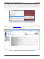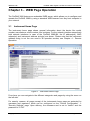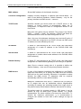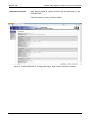
1
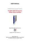
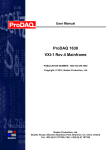
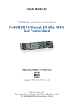
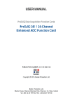
USER MANUAL ProDAQ VXI Data Acquisition Systems ProDAQ 3080 Gigabit Ethernet VXIbus Slot-0 Interface PUBLICATION NUMBER: 3080-XX-UM-1030 Copyright, © 2014, Bustec Production, Ltd. Bustec Production, Ltd. Bustec House, Shannon Business Park, Shannon, Co. Clare, Ireland Tel: +353 (0) 61 707100, FAX: +353 (0) 61 707106 PROPRIETARY NOTICE This document and the technical data herein disclosed, are proprietary to Bustec Ltd., and shall not, without express written permission of Bustec Ltd, be used, in whole or in part to solicit quotations from a competitive source or used for manufacture by anyone other than Bustec Ltd. The information herein has been developed at private expense, and may only be used for operation and maintenance reference purposes or for purposes of engineering evaluation and incorporation into technical specifications and other documents, which specify procurement of products from Bustec Ltd. This document is subject to change without further notification. Bustec Ltd. Reserve the right to change both the hardware and software described herein. Table of Contents CHAPTER 1 - INTRODUCTION .......................................................................................... 5 1.1 Overview ............................................................................................................... 5 CHAPTER 2 - GETTING STARTED.................................................................................... 7 2.1 Unpacking and Inspection ..................................................................................... 7 2.2 Installing the ProDAQ 3080 Interface .................................................................... 8 2.2.1 Configuring the Logical Address ....................................................................... 8 2.2.2 Installing the ProDAQ 3080 into the Mainframe ................................................ 9 2.3 Connecting the ProDAQ 3080 Interface ................................................................ 9 2.4 Accessing the ProDAQ 3080 ............................................................................... 11 2.4.1 Accessing the ProDAQ 3080 using Multicast DNS ......................................... 11 2.4.2 Discovering the ProDAQ 3080 using VXI-11 Broadcast ................................. 13 CHAPTER 3 - WEB PAGE OPERATION .......................................................................... 15 3.1 Instrument Home Page ........................................................................................ 15 3.2 IP Configuration ................................................................................................... 17 3.3 VXIbus Instruments ............................................................................................. 20 3.3.1 Instrument Information and Access ................................................................ 21 3.3.2 Resource Manager Output.............................................................................. 22 3.3.3 VXI Trigger Control ......................................................................................... 22 3.4 Device Status ...................................................................................................... 23 3.4.1 Advanced Status ............................................................................................. 25 3.5 System Log.......................................................................................................... 26 3.6 Device Configuration ........................................................................................... 26 3.6.1 General Settings ............................................................................................. 27 3.6.2 Security Settings ............................................................................................. 27 3.6.3 VXIbus Settings .............................................................................................. 28 3.6.4 Interrupt Configuration .................................................................................... 30 3.6.5 CLK10 Configuration....................................................................................... 31 3.6.6 Reboot Device ................................................................................................ 31 3.6.7 Firmware Update ............................................................................................ 32 3.7 Datasheet and Manual Pages ............................................................................. 33 CHAPTER 4 - REMOTE OPERATION .............................................................................. 34 4.1 4.2 TCP/IP Instrument Access .................................................................................. 34 Mapped Interface Access .................................................................................... 34 III Table of Figures Figure 1 - Logical Address Switch Location ......................................................................... 8 Figure 2 - Installing the ProDAQ 3080 into a C-Size Mainframe .......................................... 9 Figure 3 - ProDAQ 3080-AA/BA Ethernet Port(s) .............................................................. 10 Figure 4 - Using Bustec Agent to search for mDNS enabled devices ................................ 12 Figure 5 - Using DNSSD Firefox add-on to discover the ProDAQ 3080 ............................ 12 Figure 6 - Instrument Home Page ..................................................................................... 15 Figure 7 - IP Configuration Page, secondary Network Interface is disabled ...................... 17 Figure 8 - ProDAQ 3080-BA IP Configuration Page, both network interfaces enabled. ..... 19 Figure 9 - VXIbus Instruments Page .................................................................................. 20 Figure 10 - Instrument Information and Access Page ........................................................ 21 Figure 11 - Instrument Memory I/O .................................................................................... 21 Figure 12 - Resource Manager Output Page ..................................................................... 22 Figure 13 - VXIbus Trigger Control .................................................................................... 23 Figure 14 - Device Status Page ......................................................................................... 24 Figure 15 - Advanced Status Page .................................................................................... 25 Figure 16 - System Log Page ............................................................................................ 26 Figure 17 - Device Configuration Page .............................................................................. 26 Figure 18 - General Configuration Page ............................................................................ 27 Figure 19 - Security Settings Page .................................................................................... 28 Figure 20 - VXIbus Settings Page ...................................................................................... 28 Figure 21 - Interrupt Configuration Page............................................................................ 30 Figure 22 - CLK10 Configuration Page .............................................................................. 31 Figure 23 – Firmware Update Page ................................................................................... 32 Figure 24 - Firmware Upload Progress .............................................................................. 33 Figure 25 - VISA Configuration Utility ................................................................................ 35 Figure 26 - Add New Interface Dialog ................................................................................ 35 Figure 27 - Map Network Interface Dialog ......................................................................... 36 Figure 28 - Updated Available Interfaces List .................................................................... 36 Figure 29 – Updated list of configured interfaces ............................................................... 37 Figure 30 - Resource Manager .......................................................................................... 37 Figure 31 – Bustec VISA Assistant .................................................................................... 38 IV 3080-XX-UM ProDAQ 3080 Gigabit LAN Slot-0 Interface User Manual Chapter 1 - Introduction 1.1 Overview The ProDAQ 3080 Gigabit Ethernet VXIbus Slot-0 Interface provides access to VXIbus instruments through a standard Gigabit LAN interface using the VXI-11 protocol. It is designed to function as a bridge between the established, time-tested and proven base of VXIbus instruments and the IEEE 802 Ethernet, which allows you to build any size of test and measurement system simply by connecting the instruments via standard LAN to your computer. The ProDAQ 3080 provides up to two standardized Gigabit LAN interfaces with support for the VXI-11 protocol and an embedded WEB interface. It utilizes the new Tundra Tsi148 bridge to support the 2eVME block transfers specified in the revision 3.0 of the VXI standard in addition to all standard transfer modes. This allows for high-speed data transfers while maintaining backward compatibility to existing VXI rev. 1.3, 1.4 and 2.0 instruments. The ProDAQ 3080 is fully compliant to the VXIplug&play standard. Access to the 3080 and the VXIbus instruments is provided through a standard VISA library. This allows for backward compatibility with existing VXIplug&play drivers and application software. The VXIbus resource manager is embedded in the 3080 firmware and automatically executed at power-up. The embedded WEB interface allows configuring and controlling the ProDAQ 3080 VXIbus Gigabit LAN Slot-0 interface and provides access to the VXIbus instruments via a standard WEB browser. Communication with the host processor via the front-panel Gigabit Ethernet port(s) is done via standard Cat 5e Ethernet cable for distances up to 200 meters. Low-cost Gigabit Ethernet switches can be used to increase the maximum distance as well as to connect multiple mainframes to a single host or to integrate multiple mainframes and hosts into a network. Note: To achieve maximum performance, connect the ProDAQ 3080 to a host featuring a Gigabit LAN interface. If you are using switches or hubs in your network connection, make sure that they conform to the Gigabit Ethernet standard and are able to operate at that speed. For synchronization in legacy systems, the ProDAQ 3080 features a front-panel trigger input/output and CLK10 I/O via SMB connectors. Copyright ©2007-2013 Bustec Production Ltd. Page 5 of 39 ProDAQ 3080 Gigabit LAN Slot-0 Interface User Manual 3080-XX_UM This page was intentionally left blank. Page 6 of 39 Copyright ©2007-2013 Bustec Production Ltd. 3080-XX-UM ProDAQ 3080 Gigabit LAN Slot-0 Interface User Manual Chapter 2 - Getting Started The ProDAQ 3080 Gigabit Ethernet VXIbus Slot-0 Interface is a single slot, C-size VXIbus instrument and can be installed in any slot of a standard C-size VXI mainframe. To be Slot-0 controller for the VXIbus system, it must be installed in the leftmost slot of the VXI mainframe (slot “0“). If it is installed in any other slot of a VXI mainframe, all slot-0 capabilities (MODID, CLK10, etc.) will be automatically turned off. Attention: To allow access to instruments in the VXI mainframe, the ProDAQ 3080 MUST be installed in the leftmost slot of the VXI mainframe (slot "0"). Installing it into any other slot will only allow you to access the device itself (e.g. for configuration purposes). Installing it into any other slot will only allow you to access the device itself (e.g. for configuration purposes). If you do so, please make sure to set up the logical address correctly to avoid any collision with a slot-0 device already present in the mainframe. Note: The ProDAQ 3080 Gigabit Ethernet VXIbus Slot-0 Interface does not extend the VXI backplane between mainframes in a multi-mainframe system. This means that devices sharing the local bus must be installed in the same mainframe. To install the ProDAQ 3080 Gigabit Ethernet VXIbus Slot-0 Interface and the necessary software on your system, use the installation sequence as described in this chapter: 2.1 Step 1: Unpacking and Inspection Step 2: Installing the ProDAQ 3080 Step 3: Connecting the ProDAQ 3080 Interface Step 4: Bustec VISA installation (please refer to Bustec VISA Library and Tools User Manual) Step 5: Accessing the ProDAQ 3080 Unpacking and Inspection All ProDAQ modules are shipped in an antistatic package to prevent any damage from electrostatic discharge (ESD). Proper ESD handling procedures must always be used when packing, unpacking or installing any ProDAQ module, ProDAQ plug-in module or ProDAQ function card: Ground yourself via a grounding strap or similar, e.g. by holding to a grounded object. Remove the ProDAQ module from its carton, preserving the factory packaging as much as possible. Discharge the package by touching it to a grounded object, e.g. a metal part of your VXIbus chassis, before removing the module from the package. Copyright ©2007-2013 Bustec Production Ltd. Page 7 of 39 ProDAQ 3080 Gigabit LAN Slot-0 Interface User Manual 3080-XX_UM Inspect the ProDAQ module for any defect or damage. Immediately notify the carrier if any damage is apparent. Only remove the module from its antistatic bag if you intend to install it into a VXI mainframe or similar. When reshipping the module, use the original packing material whenever possible. The original shipping carton and the instrument’s plastic foam will provide the necessary support for safe reshipment. If the original anti-static packing material is unavailable, wrap the ProDAQ module in anti-static plastic sheeting and use plastic spray foam to surround and protect the instrument. 2.2 Installing the ProDAQ 3080 Interface To prevent damage to the ProDAQ module being installed, it is recommended to remove the power from the mainframe or to switch it off before installing. 2.2.1 Configuring the Logical Address To allow a host to control the VXI devices in the mainframe via the network using the ProDAQ 3080, the ProDAQ 3080 must be installed as the slot-0 controller for the mainframe, i.e. it must be installed in the leftmost slot of the mainframe (slot "0") and must be configured for using logical address 0 (zero). The logical address switch is located on the back of the module. Figure 1 shows the location of the logical address switch on the ProDAQ 3080. Set each switch to ‘Off’ for a logical one (1) and to ‘On’ for a logical zero (0). The picture shows the address switch set to logical address zero (0). 1 2 3 4 5 6 7 8 log. "1" log. "0" Figure 1 - Logical Address Switch Location Page 8 of 39 Copyright ©2007-2013 Bustec Production Ltd. 3080-XX-UM ProDAQ 3080 Gigabit LAN Slot-0 Interface User Manual 2.2.2 Installing the ProDAQ 3080 into the Mainframe Insert the module into the mainframe using the guiding rails inside the mainframe as shown in Figure 2. Push the module slowly into the slot until the backplane connectors of the module seat firmly in the corresponding backplane connectors. The top and bottom of the front panel of the module should touch the mounting rails in the mainframe. Figure 2 - Installing the ProDAQ 3080 into a C-Size Mainframe Note: To ensure proper grounding of the module, tighten the front panel mounting screws after installing the module in the mainframe. 2.3 Connecting the ProDAQ 3080 Interface The ProDAQ 3080 is equipped with one or two standard RJ-45 network connectors, accepting standard Cat 3, Cat 5, Cat 5e and Cat 6 Ethernet cables. However, to run the interface in a network using 1000BASE-T mode, in minimum Cat 5e (better Cat 6) cables are required. The figure on the next page shows the location of the LAN connector(s) on the ProDAQ 3080-AA and ProDAQ 3080-BA front panel. The connector features two LED indicators showing the speed and the link status of the connection made (see Table 1). Copyright ©2007-2013 Bustec Production Ltd. Page 9 of 39 ProDAQ 3080 Gigabit LAN Slot-0 Interface User Manual 3080-XX_UM Ethernet Port Ethernet Ports Figure 3 - ProDAQ 3080-AA/BA Ethernet Port(s) LED SPEED ACT Color Description Off No link Yellow 10BASE-T/100BASE-T operation Green 1000BASE-T operation Off No Activity Blinking Green Activity proportional to bandwidth utilization. Table 1 - LAN Status Indicators Page 10 of 39 Copyright ©2007-2013 Bustec Production Ltd. 3080-XX-UM 2.4 ProDAQ 3080 Gigabit LAN Slot-0 Interface User Manual Accessing the ProDAQ 3080 In order to get the full access capability to ProDAQ 3080 (mapping to VXI), the Bustec VISA must be installed and used for communication. Other connection methods – to the web interface, or using TCPIP-type VISA resource may be achieved by, respectively, any web browser or VISA library. By default, the ProDAQ 3080 uses DHCP to configure its network interface. If no DHCP server is found in the network, it will attempt to obtain a network address using AutoIP. The AutoIP addresses are allocated from the reserved range 169.254.1.0 169.254.254.255. The ProDAQ 3080 will select a random address from that range. If the address is already in use, another trial is done until there are no conflicts. By using the embedded web interface, the ProDAQ 3080 can be also configured to use a static IP address. If the IP address is known, the web interface can be opened by typing the address in any web browser: http://<IP ADDRESS> The device can be also accessed (with any VISA) using the following resource string: TCPIP<n>::<IP ADDRESS>::vxi0::INSTR 2.4.1 Accessing the ProDAQ 3080 using Multicast DNS ProDAQ 3080 announces, using mDNS that it provides “http” and “vxi-11” interfaces. In order to make use of it, a Multicast DNS service must be running on the host. With mDNS host name it is possible to access the device not knowing the actual IP address. Multicast DNS services are provided for Windows by Bonjour www.apple.com) and for Linux by Avahi (available at www.avahi.org). (available at The default mDNS service name for ProDAQ 3080 is: Bustec Ltd – ProDAQ 3080 – <SERIAL NUMBER> And the default host name is: prodaq3080-<SERIAL NUMBER>.local With the default host name, accessing the web interface is achieved with the following HTTP address: http://prodaq3080-<SERIAL NUMBER>.local And the VISA resource can be accessed with: TCPIP<n>::prodaq3080-<SERIAL NUMBER>.local::vxi0::INSTR Copyright ©2007-2013 Bustec Production Ltd. Page 11 of 39 ProDAQ 3080 Gigabit LAN Slot-0 Interface User Manual 3080-XX_UM The host name may be changed by the user, so having an automatic search for mDNS enabled devices is very useful. The user doesn’t need to know neither the IP address nor the host name of the device. If Bonjour (Windows) or Avahi (Linux) is running on the host, the Bustec Agent tool makes use of it. It scans for the available devices, lists them and allows opening their web interfaces. Figure 4 - Using Bustec Agent to search for mDNS enabled devices There are other tools that give similar functionality as well. For example: DNSSD add-on for Firefox, available at addons.mozilla.org. Figure 5 - Using DNSSD Firefox add-on to discover the ProDAQ 3080 Page 12 of 39 Copyright ©2007-2013 Bustec Production Ltd. 3080-XX-UM ProDAQ 3080 Gigabit LAN Slot-0 Interface User Manual 2.4.2 Discovering the ProDAQ 3080 using VXI-11 Broadcast The Bustec VISA Configuration Utility can be used to discover ProDAQ 3080 modules using the VXI-11 protocol. To discover ProDAQ 3080, the device type VXI with device number 0 must fit within the search criterion (it does by default). The discovered ProDAQ 3080s are added to the Network Instruments list as VISA resources: TCPIP<n>::<IP ADDRESS>::vxi0::INSTR For the detailed description of the procedure please refer to Bustec VISA Library and Tools User Manual. Copyright ©2007-2013 Bustec Production Ltd. Page 13 of 39 ProDAQ 3080 Gigabit LAN Slot-0 Interface User Manual 3080-XX_UM This page was intentionally left blank. Page 14 of 39 Copyright ©2007-2013 Bustec Production Ltd. 3080-XX-UM ProDAQ 3080 Gigabit LAN Slot-0 Interface User Manual Chapter 3 - WEB Page Operation The ProDAQ 3080 features an embedded WEB server, which allows you to configure and operate the ProDAQ 3080 by using a standard WEB browser from any host computer in your network. 3.1 Instrument Home Page The instrument home page shows general information about the device like model number, manufacturer, serial number, and revisions. For the network interface respectively both network interfaces in case of the ProDAQ 3080-BA, the IP address(es), MAC adress(es) and instrument address string(s) are shown. Please note that the instrument address string is not the one used in all operation modes, see Chapter 4 - Remote Operation. Figure 6 - Instrument Home Page From here you can navigate to the different categories and pages by using the menu on the left side. For security reasons, all pages except of the instruments home page are protected by username and password, which can be configured on the "Device Configuration" -> "Security Settings" page. Upon delivery, the username and is set to "admin" and the password to "1234". Copyright ©2007-2013 Bustec Production Ltd. Page 15 of 39 ProDAQ 3080 Gigabit LAN Slot-0 Interface User Manual Page 16 of 39 3080-XX_UM Copyright ©2007-2013 Bustec Production Ltd. 3080-XX-UM 3.2 ProDAQ 3080 Gigabit LAN Slot-0 Interface User Manual IP Configuration The IP Configuration Page shows the current settings and allows you to change the configuration for the ProDAQ 3080's LAN interface(s). Network Interface #1 is present on both versions (-AA and -BA) of the ProDAQ 3080 and is always enabled. On the ProDAQ 3080-AA the secondary interface is not available and therefore permanently switched off in the IP Configuration Page. On the ProDAQ 3080-BA, the secondary Interface may be switched on and off. Figure 7 - IP Configuration Page, secondary Network Interface is disabled The displayed configuration and user-editable settings are the following: Hostname User defined hostname for the device (without domain). Clear this value to revert to factory default. Note: Multicast DNS domain is always: “.local”. Dynamic DNS domain depends on the network configuration. User Description User defined description of the device – it is displayed on the Home Page along with user defined Asset Number (see Device Configuration). Copyright ©2007-2013 Bustec Production Ltd. Page 17 of 39 ProDAQ 3080 Gigabit LAN Slot-0 Interface User Manual 3080-XX_UM Clear this value to revert to factory default. MAC address Shows MAC address of the Network Interface. Current IP configuration Displays currently assigned: IP Address and Subnet Mask – for each of two Network Interfaces, Default Gateway – only for the primary interface and DNS servers – common. TCP/IP mode Specifies whether the device shall use a DHCP server in the network, or AutoIP protocol to automatically obtain the IP configuration, or maybe the static IP configuration defined in the form below. More than one option may be selected. The priority is as follows: DHCP → AutoIP → Static. For example, if DHCP and Static are selected and DHCP fails, the Static configuration is set. Note: Only one of the Network Interfaces may use AutoIP option. If none of them are configured to use DHCP, at least one DNS server IP address must be defined by the user. IP Address If "Static IP" was selected as the TCP/IP mode, this field allows assignment of a static IP address to the ProDAQ 3080 LAN interface(s). Subnet mask If "Static IP" was selected as the TCP/IP mode, this field allows assignment of a static subnet mask address to the ProDAQ 3080s LAN interface(s). Default Gateway If "Static IP" was selected as the TCP/IP mode, this field allows assignment of a static default gateway for the routing of IP packets. Note: Due to common routing rules it is possible to define one Default Gateway – here only for the primary Network Interface. DNS Servers If none of the Network Interfaces are configured to use DHCP, these two fields allow you to specify the DNS server the ProDAQ 3080 will use for name resolving. Otherwise it is possible to select whether the DNS servers’ IP addresses shall be acquired automatically (DHCP) or user-defined (Static). MTU Maximum Transmission Unit (MTU) – maximum size (in bytes) of an IP packet that can be transmitted without fragmentation (including IP headers, but excluding headers from lower levels in the protocol stack). Each Network Interface has own MTU setting. The default value for a typical network is 1500 bytes. It can be defined as high as 9000 bytes (jumbo frames). For correct interoperation, the whole network must have the same MTU. To achieve the maximum performance, it is recommended to configure the network to work with a MTU settings as high as possible. Page 18 of 39 Copyright ©2007-2013 Bustec Production Ltd. 3080-XX-UM mDNS Service Name ProDAQ 3080 Gigabit LAN Slot-0 Interface User Manual User defined name of mDNS services that are advertised by the ProDAQ 3080. Clear this value to revert to factory default. Figure 8 - ProDAQ 3080-BA IP Configuration Page, both network interfaces enabled. Copyright ©2007-2013 Bustec Production Ltd. Page 19 of 39 ProDAQ 3080 Gigabit LAN Slot-0 Interface User Manual 3.3 3080-XX_UM VXIbus Instruments The VXIbus Instruments Configuration page shows a table with the VXIbus instruments identified by the embedded resource manager on start-up. Figure 9 - VXIbus Instruments Page By pressing the "More..." buttons to the right of an instruments entry, a separate page with additional information about the particular device is shown (see 3.3.1 ), where you can perform basic I/O operations in a way similar to the VISA assistant. The "Show Resource Manager Output" button displays the log file written by the embedded resource manager on start-up. The “VXI Trigger Control” button lets you access a page where you can set the routing of the VXIbus backplane trigger lines and the ProDAQ 3080 front panel trigger I/Os. Page 20 of 39 Copyright ©2007-2013 Bustec Production Ltd. 3080-XX-UM ProDAQ 3080 Gigabit LAN Slot-0 Interface User Manual 3.3.1 Instrument Information and Access The “Instrument Information and Access” page shows detailed information about the VXIbus instrument as discovered by the embedded resource manager. Figure 10 - Instrument Information and Access Page Depending on the type of instrument you can perform basic memory or message based access operations on the device by selecting the “Memory I/O” or “Basic I/O” buttons at the bottom of the page. Figure 11 - Instrument Memory I/O Copyright ©2007-2013 Bustec Production Ltd. Page 21 of 39 ProDAQ 3080 Gigabit LAN Slot-0 Interface User Manual 3080-XX_UM 3.3.2 Resource Manager Output The “Resource Manager Output” page lets you review the output of the embedded VXIbus resource manager. Figure 12 - Resource Manager Output Page 3.3.3 VXI Trigger Control The “VXI Trigger Control” page allows you to route the VXIbus trigger lines from/to the front panel trigger I/Os on the ProDAQ 3080. By choosing the “Front Panel Trigger In” selection for any or all of the VXIbus TTL and ECL trigger lines or the Front Panel Trigger Output line, any trigger received on the front panel trigger input line of the ProDAQ 3080 will be routed to any or all of the chosen lines. While “Unrouted” and “Front Panel Trigger In” are the only possible sources for trigger events for the VXIbus TTL and ECL Trigger lines, the front panel trigger output line can also receive trigger events from the VXIbus TTL and ECL trigger lines. In addition to routing the trigger lines, each of the trigger lines can be asserted, deasserted or a pulse can be generated by using the buttons “Assert”, “Deassert” or “Pulse” to the right of each trigger line source selection. Page 22 of 39 Copyright ©2007-2013 Bustec Production Ltd. 3080-XX-UM ProDAQ 3080 Gigabit LAN Slot-0 Interface User Manual Figure 13 - VXIbus Trigger Control 3.4 Device Status The “Device Status” page shows the overall status of the ProDAQ 3080 and its network connection. For a more detailed status, select the “Show advanced status” button at the bottom. Copyright ©2007-2013 Bustec Production Ltd. Page 23 of 39 ProDAQ 3080 Gigabit LAN Slot-0 Interface User Manual 3080-XX_UM Figure 14 - Device Status Page Page 24 of 39 Copyright ©2007-2013 Bustec Production Ltd. 3080-XX-UM ProDAQ 3080 Gigabit LAN Slot-0 Interface User Manual 3.4.1 Advanced Status The “Advanced Status” page allows you to view the output of several tools and contents of configuration files available on the ProDAQ 3080. To switch between the different outputs/files, just select the tool/file with the combo box at the bottom. The “Refresh” button allows updating the status. Figure 15 - Advanced Status Page The following tools and configuration files are available: ifconfig Shows the output of the “ifconfig” utility with detailed information on the network interface status. For detailed information, please refer to the Linux manual page for “ifconfig”. route Shows the routing table as seen by the embedded Linux kernel on the ProDAQ 3080. resolv.conf Displays the contents of the resolv.conf file. The resolv.conf file is maintained by networking scripts and shows the current nameserver configuration in use by the ProDAQ 3080 kernel. hosts Displays the contents of the hosts file. The hosts file contains the known host aliases. device.conf The device.conf file holds the static settings configured via the “IP Setup” page. device and firmware revision Shows the revisions of the different parts of the system. Copyright ©2007-2013 Bustec Production Ltd. Page 25 of 39 ProDAQ 3080 Gigabit LAN Slot-0 Interface User Manual 3.5 3080-XX_UM System Log The “System Log” page shows the output of the kernel logging facility. Figure 16 - System Log Page 3.6 Device Configuration The device configuration is split up into several sub-items. Figure 17 - Device Configuration Page Page 26 of 39 Copyright ©2007-2013 Bustec Production Ltd. 3080-XX-UM ProDAQ 3080 Gigabit LAN Slot-0 Interface User Manual Click on one of the buttons to the right of the different sections to access it. Each sub-item lets you configure a part of the ProDAQ 3080. In addition the page contains two buttons to either reboot the device or to update the firmware. 3.6.1 General Settings This page allows you to change the system time and assign an asset number to the device, which will be shown on the instrument home page. Figure 18 - General Configuration Page 3.6.2 Security Settings On this page you can change the password that is used to protect the pages of the ProDAQ 3080. Please type in your old password, the new one and confirm it by re-typing. Copyright ©2007-2013 Bustec Production Ltd. Page 27 of 39 ProDAQ 3080 Gigabit LAN Slot-0 Interface User Manual 3080-XX_UM Figure 19 - Security Settings Page 3.6.3 VXIbus Settings The VXIbus Settings page allows you to configure how the ProDAQ 3080 accesses the VXIbus. Figure 20 - VXIbus Settings Page Bus Timeout Page 28 of 39 The time the on-board timer needs to expire once a VXIbus access by the 3080 is started. If it expires, a VXIbus slave did not respond correctly and a bus error is generated. Possible values are: 16 µsec, 32 µsec, 64 µsec, 128 Copyright ©2007-2013 Bustec Production Ltd. 3080-XX-UM ProDAQ 3080 Gigabit LAN Slot-0 Interface User Manual µsec, 256 µsec, 512 µsec and 1024 µsec Bus Arbiter Mode Selects the bus arbiter mode. Possible values are: “Priority” or “Round Robin”. (Remark: The arbiter is only enabled if the module is placed in the leftmost slot of a VXI mainframe, slot “0”). Bus Arbiter Timeout Specifies the timeout for the arbiter. Possible values are: Disabled, 16 µsec, 256 µsec. Bus Requester Mode Sets the request mode of the ProDAQ 3080, “Fair” or “Demand”. Bus Requester Level Selects the request level the module is using when accessing the VXIbus. Possible values are 3 to 0, with 3 as the highest priority and 0 as the lowest. Bus Req. Release Mode Selects the release mode: “RWD” (release when done) or “ROR” (release on request). Access Counter "On" Sets the number of bytes to transfer before a bus access can be interrupted. Possible values are 0 (disabled), 256 bytes, 1024 bytes, 2048 bytes, 4096 bytes, 8192 bytes and 16384 bytes. Access Counter "Off" Sets the time the accesses are paused before a new block is started. Possible values are: 0 (disabled), 2 µs, 4 µs, 8 µs, 16 µs, 32 µs, 64 µs, 128 µs, 256 µs, 512 µs and 1024 µs. Note: Please note that any changes will be applied only at the next reboot of the device. Copyright ©2007-2013 Bustec Production Ltd. Page 29 of 39 ProDAQ 3080 Gigabit LAN Slot-0 Interface User Manual 3080-XX_UM 3.6.4 Interrupt Configuration The Interrupt Configuration page allows configuring the usage of the VXIbus interrupt lines in the allocation mechanism of the VXI resource manager. Figure 21 - Interrupt Configuration Page For each of the VXIbus interrupt lines (Level 1 to Level 7) one of two settings for the assignment can be chosen : Auto This setting will allow the resource manager to use the interrupt line for this level in his allocation mechanism. None This setting will prevent the resource manage to use the interrupt line for this level in his allocation mechanism. This setting must be used if a instrument in the system does not allow the dynamic allocation of interrupt lines and wants to use one or more lines permanently allocated. Page 30 of 39 Copyright ©2007-2013 Bustec Production Ltd. 3080-XX-UM ProDAQ 3080 Gigabit LAN Slot-0 Interface User Manual 3.6.5 CLK10 Configuration This page allows you to enable or disable the CLK10 output on the ProDAQ 3080 front panel. Figure 22 - CLK10 Configuration Page 3.6.6 Reboot Device If for any reason you need to reboot the ProDAQ 3080 remotely, you can use the button “Reboot Device” in the “Device Configuration” page. To avoid accidental usage of this feature, selecting the button will cause a verification dialog to pop-up before the actual reboot starts. Note: Please allow sufficient time for the device to reboot before trying to access it again. Please note as well that depending on your IP and network configuration the device may use a different IP address after reboot (e.g. DHCP). Copyright ©2007-2013 Bustec Production Ltd. Page 31 of 39 ProDAQ 3080 Gigabit LAN Slot-0 Interface User Manual 3080-XX_UM 3.6.7 Firmware Update To update the firmware on the ProDAQ 3080, use the “Update Firmware” button on the “Device Configuration” page. Figure 23 – Firmware Update Page First save the file containing the new image on your local host. Press the "Browse..." to open the file upload dialog, which allows you to browse through your file system and select the file to upload. Once the correct file is selected, press the "Update Firmware" button. The upload progress and the programming progress will be displayed by a progress bar below the file selection control. Page 32 of 39 Copyright ©2007-2013 Bustec Production Ltd. 3080-XX-UM ProDAQ 3080 Gigabit LAN Slot-0 Interface User Manual Figure 24 - Firmware Upload Progress During the upload and programming, do not navigate away from the page by using the browser controls. Any interruption of the update process might render the ProDAQ 3080 unusable. WARNING Depending on your connection speed uploading and programming a new firmware image may take several minutes. To safely complete the process, do not navigate away from the page and do not interrupt the connection to the ProDAQ 3080 or power-cycle the mainframe. 3.7 Datasheet and Manual Pages The “Datasheet” and “Manual” pages allow you to view the ProDAQ 3080 datasheet and user manual. Copyright ©2007-2013 Bustec Production Ltd. Page 33 of 39 ProDAQ 3080 Gigabit LAN Slot-0 Interface User Manual 3080-XX_UM Chapter 4 - Remote Operation The ProDAQ 3080 Gigabit LAN Slot-0 Interface features a VXI-11 RPC server, which allows the access from remote hosts via the VISA library. This access can be done in two ways, either by accessing the VXIbus instruments separately as TCP/IP instruments or by mapping the ProDAQ 3080 into the remote VISA configuration as a standard VXIbus interface. 4.1 TCP/IP Instrument Access To access the VXIbus instruments installed in the same mainframe as the ProDAQ 3080 interface, you will need to use resource strings in the format TCPIP[board]::<host address>::<interface>,<logical address>[::INSTR] where [board] is the optional index of the LAN interface devices (as default, device 0 is used); <host address> specifies the host name or IP number of the ProDAQ 3080 interface; <interface> specifies which interface on the ProDAQ 3080 to use (only "vxi0" is supported) and <logical address> specifies the logical address of the VXIbus instruments to access. The specification "::INSTR" is optional. Example: If the ProDAQ 3080 is configured to use IP address 192.168.2.80 and is installed in the same mainframe as a VXIbus device configured for using logical address 2, access to this device can be gained by using the open statement status = viOpen(rm_session, “TCPIP::192.168.2.80::vxi0,2::INSTR”, VI_NULL, VI_NULL, &instr_session); Hence, as the VXI-11 standard allows only for read/write RPC messages, only message based VXIbus instruments can be operated in this way. 4.2 Mapped Interface Access To gain access to all VXIbus instruments via the ProDAQ 3080 Gigabit LAN Slot-0 Interface, it is necessary to map the ProDAQ 3080 as a standard VXIbus interface onto the host system. To do so, select the “Bustec VISA Configuration Utility” in the Bustec VISA program group created during the installation of the VISA library (“Start” “Programs” “Bustec VISA”). Alternatively you can use a link in Bustec Agent. This will start the configuration tool for the VISA library and attached hardware interfaces. Page 34 of 39 Copyright ©2007-2013 Bustec Production Ltd. 3080-XX-UM ProDAQ 3080 Gigabit LAN Slot-0 Interface User Manual Figure 25 - VISA Configuration Utility To add a new interface, select “Add Interfaces”. A new dialog “Add New Interface” is shown with a list of all devices found in the system. The already configured are disabled. Each interface is listed with its type and with a description containing the serial number of the device. To map a remote interface, select the "Map Network Interface" button at the bottom. Figure 26 - Add New Interface Dialog In the "Map Network Interface" dialog you can specify the network address of the remote interface and the local interface on the remote server to use. In case ProDAQ 3080 only “vxi0” is supported. The TCPIP interface number is a virtual value. It allows differentiation of TCPIP interfaces in case of conflict management when there are multiple VISAs installed in the system. Copyright ©2007-2013 Bustec Production Ltd. Page 35 of 39 ProDAQ 3080 Gigabit LAN Slot-0 Interface User Manual 3080-XX_UM Figure 27 - Map Network Interface Dialog Click “Ok” to add the network interface. The procedure can be repeated to add more ProDAQ 3080 network interfaces for mapping. Once the network interfaces are added, they can be configured with VXI interface numbers. The VXI interface numbers are assigned automatically from the pool of not yet used values. In order to change them, just select an interface and modify the value using the spin box control in the bottom. Figure 28 - Updated Available Interfaces List Finally click “Add all” or “Add selected”. The list in the main dialog will be updated with the newly added interfaces. Page 36 of 39 Copyright ©2007-2013 Bustec Production Ltd. 3080-XX-UM ProDAQ 3080 Gigabit LAN Slot-0 Interface User Manual Figure 29 – Updated list of configured interfaces As the remote interface is now mapped as a standard VXIbus interface onto the computer, the resource manager need to run to retrieve the instrument configuration from the remote host. To run the resource manager, select “Bustec VXIbus Resource Manager” from the Bustec VISA program group in the start menu (“Start” “Programs” “Bustec VISA”) or use the link in Bustec Agent. Figure 30 - Resource Manager Copyright ©2007-2013 Bustec Production Ltd. Page 37 of 39 ProDAQ 3080 Gigabit LAN Slot-0 Interface User Manual 3080-XX_UM Note The VISA library is a shared library that initializes itself when it is first loaded by an application. Applications started while the VISA library is already loaded just share this configuration. Only when all applications using the VISA library are stopped, it will be unloaded by the system. Therefore all applications using the VISA library must be closed before running the resource manager or using the VISA configuration utility. Take special care while using integrated development environments, they will keep the VISA library loaded even when the application developed in them was stopped. When the Resource Manager retrieves the configuration from the ProDAQ 3080 host, it’s possible to access the remote VXI resources using VXI rather than TCPIP interface. The Bustec VISA Assistant tool can be used to easily access the configured interfaces without programming. Figure 31 – Bustec VISA Assistant For more information on the tools coming with the Bustec VISA and application programming using the VISA library please refer to Bustec VISA Library and Tools User Manual. Page 38 of 39 Copyright ©2007-2013 Bustec Production Ltd. Bustec Ltd. Bustec House, Shannon Business Park Shannon, Co. Clare, Ireland Tel: +353 (0) 61 707100, FAX: +353 (0) 61 707106