1
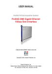
User Manual
ProDAQ 1630
VXI-1 Rev.4 Mainframe
PUBLICATION NUMBER: 1630-XX-UM-1000
Copyright, © 2013, Bustec Production, Ltd.
Bustec Production, Ltd.
Bustec House, Shannon Business Park, Shannon, Co. Clare, Ireland
Tel: +353 (0) 61 707100, FAX: +353 (0) 61 707106
PROPRIETARY NOTICE
This document and the technical data herein disclosed, are proprietary to Bustec
Production Ltd., and shall not, without express written permission of Bustec
Production Ltd, be used, in whole or in part to solicit quotations from a competitive
source or used for manufacture by anyone other than Bustec Production Ltd. The
information herein has been developed at private expense, and may only be used for
operation and maintenance reference purposes or for purposes of engineering
evaluation and incorporation into technical specifications and other documents,
which specify procurement of products from Bustec Production Ltd.. This document
is subject to change without further notification. Bustec Production Ltd. Reserve the
right to change both the hardware and software described herein.
Copyright,
2013 Bustec Production Ltd.
Page 2 of 20
ProDAQ 1630 VXI-1 Rev.4 Mainframe User Manual
1630-XX-UM
Table of Contents
1. Introduction .................................................................................................................. 7
1.1.
Overview .......................................................................................................................... 7
1.2.
Power Supply ................................................................................................................... 7
1.3.
Cooling ............................................................................................................................. 8
1.4.
Monitoring ........................................................................................................................ 8
2. Operation ...................................................................................................................... 9
2.1.
Front Panel Controls ....................................................................................................... 9
2.2.
Programming via the front-panel switches ................................................................. 10
2.3.
Build-in Web Server....................................................................................................... 13
2.4. VXIplug&play Driver ...................................................................................................... 14
2.4.1. Connecting to the ProDAQ 1630 .............................................................................. 14
2.5.
Getting Status Information ........................................................................................... 14
2.6.
Controlling the Fan Speed ............................................................................................ 16
3. Specifications ............................................................................................................. 17
3.1.
General ........................................................................................................................... 17
3.2.
Cooling ........................................................................................................................... 17
3.3.
Monitoring ...................................................................................................................... 17
3.4.
Electrical Performance .................................................................................................. 17
3.5.
Physical Specifications ................................................................................................. 17
Page 3 of 20
Copyright, © 2013 Bustec Production Ltd.
1630-XX-UM
ProDAQ 1630 VXI-1 Rev. 4 Mainframe User Manual
Table of Figures
Figure 1 - ProDAQ 1630 VXIbus Mainframe for VXI-1 Rev.4 Systems ........................................... 7
Figure 2 - ProDAQ 1630 Front Panel Controls ................................................................................. 9
Figure 3 - ProDAQ 1630 Web Page............................................................................................... 13
Figure 4 - Connecting to the ProDAQ 1630 ................................................................................... 14
Figure 5 - Obtaining Status Information ......................................................................................... 15
Figure 6 - Controlling the fan speed ............................................................................................... 16
Copyright,
2013 Bustec Production Ltd.
Page 4 of 20
ProDAQ 1630 VXI-1 Rev.4 Mainframe User Manual
1630-XX-UM
Reference Documents
Title
VXI-1 Rev. 4 Specification
(http://www.vxibus.org/files/VXI_Specs/VXI-1_4-0%2020100527.pdf)
Number
Glossary
Safety
This equipment contains voltage hazardous to human life and safety
and is able to inflict personal injury. Disconnect the device from the AC
line (mains) before opening the covers as described in chapter 3.4.
!
To operate this device, use a three-conductor power cord and an
power outlet providing protective earth. Do not use a two-conductor
extension cord or a three-prong/two-prong adapter.
!
If you replace the power cord provided, make sure that the
replacement is rated for the power consumption stated in the
specifications.
Do not position the device so that it is difficult to operate the
disconnecting device.
If the equipment is used in a manner not specified by the
manufacturer, its safety may be impaired.
Waste Electrical and Electronic Equipment (WEEE)
This product complies with the WEEE Directive 2002/96/EC marking
requirement. The affixed product label indicates that you must not
discard this electrical product in domestic household waste.
Product Category: Monitoring and Control Instrumentation
To return unwanted products, contact Bustec Ltd.
Page 5 of 20
Copyright, © 2013 Bustec Production Ltd.
1630-XX-UM
ProDAQ 1630 VXI-1 Rev. 4 Mainframe User Manual
(This page was intenionelly left blank)
Copyright,
2013 Bustec Production Ltd.
Page 6 of 20
ProDAQ 1630 VXI-1 Rev.4 Mainframe User Manual
1630-XX-UM
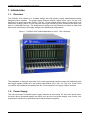
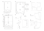
1. Introduction
1.1. Overview
The ProDAQ 1630 chassis is a compact design with high density, highly sophisticated modular
designed power supplies. The power supply features medium output power up to 2.5 kW, with
extremely low noise and ripple (PARD). The 8U, 13-slot chassis offers superior cooling due to an
efficient air guiding system. The fan tray has three high efficient DC-fans, situated at the lower rear
side in a removable fan tray. The alphanumeric display and the Ethernet port allow for both local
and remote monitoring of all supply voltages, fan speeds and temperatures.
Figure 1 - ProDAQ 1630 VXIbus Mainframe for VXI-1 Rev.4 Systems
The backplane is designed especially for the new high-speed transfer modes and additional clock
and trigger signals introduced in the VXIbus specification VXI-1 Rev. 4.0. The new, 5-row P1/P2
connectors are backwards compatible with the 3-row connectors on legacy VXIbus modules.
1.2. Power Supply
The micro-processor controlled power supply features an auto-range AC input with power factor
correction and is protected against any failure such as over- and under-voltage, over current, over
temperature and shorts to ground as well as shorts between supplies.
Page 7 of 20
Copyright, © 2013 Bustec Production Ltd.
1630-XX-UM
ProDAQ 1630 VXI-1 Rev. 4 Mainframe User Manual
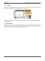
1.3. Cooling
The ProDAQ 1630 features a 3U fan tray in the rear of the chassis, a 1U compression chamber
below the VXI card cage and a 1U exhaust above the card cage.
The fan tray hosts three individually controlled long-life DC fans with an adjustable speed between
1200 and 3600 rpm.
1.4. Monitoring
The ProDAQ 1630 feature an alphanumeric display for local monitoring and a Ethernet port for
remote monitoring. The embedded Web page can be accessed with any standard browser. A
C/C++ based driver allows monitoring access from applications.
Copyright,
2013 Bustec Production Ltd.
Page 8 of 20
ProDAQ 1630 VXI-1 Rev.4 Mainframe User Manual
1630-XX-UM
2. Operation
The ProDAQ 1630 can be operated locally via the switches and display on the front panel or
remotely via the VXIplug&play driver provided.
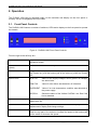
2.1. Front Panel Controls
The ProDAQ 1630 features a number of switches, LEDs and a display on the front panel to operate
the chassis.
Figure 2 - ProDAQ 1630 Front Panel Controls
From the right to the left they are:
SYS RES
System reset switch. This switch is recessed behind the panel to avoid
accidental usage.
Main Power LED
(green)
Shows the status of the main power.
Main Power Switch
Toggle Switch to power the chassis on/off. Push the top part to power
the chassis on; push the bottom part of the switch to power the chassis
off.
Status LEDs
STATUS
Status of the supply voltages. Will lit green if all voltages
are within limits.
FAN FAIL
Yellow if a fan failure was detected, off otherwise.
OVERHEAT
Yellow if an over-temperature condition was detected on
the power supply.
SYSFAIL
Shows the status of the VXIbus SYSFAIL* line. Red if the
line is asserted.
Alphanumeric Display
Allows to program or monitor voltages, fan speeds, connection
parameters etc.
MODE SELECT
Switch to step through the menus and submenus displayed in the
alphanumeric display and change settings.
SPEED
Switch to increase or decrease the speed of the fans in the fan tray.
Push the top part of the button to increase the speed or the bottom part
of the switch to decrease the speed.
Page 9 of 20
Copyright, © 2013 Bustec Production Ltd.
1630-XX-UM
ProDAQ 1630 VXI-1 Rev. 4 Mainframe User Manual
2.2. Programming via the front-panel switches
After the chassis has been powered on by using the main power switch the main operation modes
can be selected by pushing the “Mode Select” switch up or down. Many main operation modes do
have one or more submenus, which can be accessed by a special procedure.
The front panel-switches for programming are used in the following way:
Symbol
Description
Remarks
P▲
Push “Power” switch up
(Press upper part, direction “ON”)
Main operation mode:
Switch the crate on.
Submenu:
OK button. Used to enter the selected submenu,
request to change a value, accept the changes.
P▼
Push “Power” switch down
(Press lower part, direction “OFF”)
Main operation mode:
Switch the crate off.
Submenu:
CANCEL button. Used to leave a submenu,
discard the changes.
M▲
Push “Mode Select” switch up
(Press upper part of the switch)
Main operation mode:
Select the next operation mode.
Submenu:
Change the selected item to the next possible
state.
M▼
Push “Mode Select” switch down
(Press lower part of the switch)
Main operation mode:
Select the previous operation mode.
Submenu:
Change the selected item to the previous
possible state.
After the chassis is powered on using the main power switch (P▲) the “Mode Select” switch can be
used to step through the main operation modes. Once the desired main operation mode is
displayed in the alphanumeric display, the associated submenu can be entered by pushing both
the power switch and the mode select switch up and holding them in this position for approx. 4
seconds. If there is more than one submenu associated with a main operation mode, the mode
select switch (M▲ or M▼) can be again used to select the desired one. During this procedure, the
display may either display one line of constantly, alternate between two lines of information or blink
for the parts that can be altered. In the following example two lines in the “Display” column denote
the alternating display of these two lines in the display. Parts that are shown blinking in the display
are shown with alternate background color:
Copyright,
2013 Bustec Production Ltd.
Page 10 of 20
ProDAQ 1630 VXI-1 Rev.4 Mainframe User Manual
1630-XX-UM
Description
Switch
Switch the chassis on
P▲
Select the desired main operation
mode
M▲ or M▼(until the right mode is
displayed)
Enter submenu
M▲ (push and hold),
P▲ (push and hold both switches
for appr, 4 seconds)
Config: Wait
↓
Config: Wait…
↓
Config: Ready!
↓
TCPIP Address
192.168.91.80
Select submenu “TCPIP
Gateway”
M▲ or M▼(until the right
menu/setting is displayed)
TCPIP Gateway
192.168.91.94
Enter this menu
P▲
192.168.91.94
Change the value
M▲ or M▼
196.168.91.94
Accept change, to next item
P▲
196.168.91.94
Accept change, to next item
P▲
196.168.91.94
Accept change, to next item
P▲
196.168.91.94
Back to submenu selection
P▲
TCPIP Gateway
196.168.91.94
Leave submenu
M▼
TCPIP: no link
Page 11 of 20
Display
+5V 5.01V 1.2A
TCPIP: no link
Copyright, © 2013 Bustec Production Ltd.
1630-XX-UM
ProDAQ 1630 VXI-1 Rev. 4 Mainframe User Manual
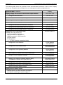
The following table shows the operation modes and associated submenus. Values in the “Display”
column are examples only and depend on your settings and module configuration etc.
Operation Mode / Submenu
Display voltage and current of the selected output channel
Change of the current limit
Fine adjustment of the output voltage
Display
+5V 5.01V 12.A
+5V Ilim 15.A
+5V Uadj +50%
Change the output voltage (coarse)
+5V Unom 5.00V
Change the overvoltage protection threshold
+5V OVP 6.00V
Change of the overcurrent switch-off threshold
+5V IOff 30.A
Change of the undervoltage switch-off threshold
+5V Umin 4.50V
Change of the overvoltage switch-off threshold
+5V Umax 5.50V
Display the TCP/IP connection state
Possible values & symbols are:
no link (no cable connected)
10M (connected to 10M network)
100M (connected to 100M network)
HD (half duplex)
FD (full duplex)
↓, ↑, ↕ (Frame received, transmitted, both)
Change the TCP/IP address
Change the TCP/IP subnet mask
Ethernet 100M FD
TCPIP Address
192.168.91.80
TCPIP SubnetMask
255.255.255.224
Change the TCP/IP gateway address
TCPIP Gateway
192.168.91.94
Allow writes (e.g. switch on/off) via the web server
HTTP:read/write
Change TCP/IP negotiation settings
TCPIPnegotiation
AutoNegotiation
Display of the ethernet hardware address (MAC).
This address is written at the type plate, too.
Change the TCP/IP port of the web server
Change the TCP/IP port of the SNMP server
Restore the default SNMP settings
TCPIP MAC Addres
0050-C22D-C231
HTTP Port 80
SNMP Port 161
SNMP Default No
Display the fan rotation speed
Change the time for which the fans will continue
running after switching the power supply off
Copyright,
2013 Bustec Production Ltd.
Page 12 of 20
ProDAQ 1630 VXI-1 Rev.4 Mainframe User Manual
1630-XX-UM
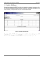
2.3. Build-in Web Server
After you have configured the TCP/IP port via the local controls, you can open the web page of the
ProDAQ 1630 in any browser simply by typing the IP address in the address line of the browser.
The web page shown displays relevant information regarding the voltages and temperatures of the
chassis and allow you to operate the main power, reset line and fan speed.
Figure 3 - ProDAQ 1630 Web Page
The button “MAIN POWER” allows you to power on/off the chassis (bus power). “VME
SYSRESET” allows you to assert the SYSRESET* line on the bus to issue a general system reset.
The buttons “FAN SLOWER” and “FAN FASTER” decrease/increase the fan speed.
Page 13 of 20
Copyright, © 2013 Bustec Production Ltd.
1630-XX-UM
ProDAQ 1630 VXI-1 Rev. 4 Mainframe User Manual
2.4. VXIplug&play Driver
The VXIplug&play driver for the ProDAQ 1630 is designed to connect to the chassis via the TCP/IP
link. You will need to configure the TCP/IP port of the ProDAQ 1630 and connect it to your network
to be able to remotely access the chassis using the driver.
2.4.1. Connecting to the ProDAQ 1630
To connect to the ProDAQ 1630, use the driver function bu1630_init() with a resource string
specifying the usage of a TCPIP socket (see Figure 4, ). The IP address used in the resource
string must be the address the chassis was configured for. Now you can use the driver function to
monitor the crate or control its settings. To close the connection, use the function bu1630_close()
(see Figure 4, ).
#include <visa.h>
#include <bu1630.h>
main (int argc, char **argv)
{
ViStatus status;
ViSession sesn;
ViChar descr[256];
/* connect to a ProDAQ 1630 */
if ((status = bu1630_init(“TCPIP0::192.168.91.80::SOCKET”,
VI_TRUE, VI_TRUE, &sesn)) != VI_SUCCESS)
{
viStatusDesc (sesn, status, descr);
printf (“Error: bu3416_init() failed due to %s\n”, descr);
return -1;
}
/* operation */
bu1630_close (sesn);
}
Figure 4 - Connecting to the ProDAQ 1630
2.5. Getting Status Information
After the connection is established, the driver functions can be used to obtain status information
from the chassis. There are several functions available:
bu1630_getMainPowerState()
returns the current status of the main power. If the
parameter onoff returns VI_TRUE, the chassis is powered
on.
bu1630_getStatus()
returns information about several items such as failures,
power and whether the SYSFAIL line was asserted.
bu1630_getOutputVoltages()
returns the current values of the output voltages supplied
to the VXIbus.
bu1630_getOutputCurrents()
returns the current values of the current used on different
the output voltages supplied to the VXIbus.
Copyright,
2013 Bustec Production Ltd.
Page 14 of 20
ProDAQ 1630 VXI-1 Rev.4 Mainframe User Manual
bu1630_getOutputStatus()
1630-XX-UM
returns the status of the output voltages supplied to the
bus. If one of the states returned as VI_TRUE, an
over/under-voltage, over-current or over-temperature
condition exists on the related supply.
The following example shows some of the functions:
#include <visa.h>
#include <bu1630.h>
main (int argc, char **argv)
{
ViStatus status;
ViSession sesn;
ViChar descr[256];
ViBoolean mainPower, inputFailure, outputFailure, fanFailure, sensorFailure, sysfail;
ViReal64 p24V_V, p12V_V, p5V_V, m2V_V, m5_2V_V, m12V_V, m24V_V;
/* connect to a ProDAQ 1630 */
if ((status = bu1630_init(“TCPIP0::192.168.91.80::SOCKET”,
VI_TRUE, VI_TRUE, &sesn)) < VI_SUCCESS)
{
viStatusDesc (sesn, status, descr);
printf (“Error: bu1630_init() failed due to %s\n”, descr);
return -1;
}
If ((status = bu1630_getStatus (sesn, &mainPower, &inputFailure, &outputFailure,
&fanFailure, &sensorFailure, &sysfail))) < VI_SUCCESS)
{
bu1630_error_message (sesn, status, descr);
printf (“Error: bu1630_ getStatus() failed due to %s\n”, descr);
return -1;
}
if (mainPower == VI_TRUE)
printf (“Chassis is powered on!\n”);
if (inputFailure == VI_TRUE)
printf (“Input Power failure happened!\n”);
if (outputFailure == VI_TRUE)
printf (“Output Power failure happened!\n”);
if (fanFailure == VI_TRUE)
printf (“Fan Tray failure happened!\n”);
if (sensorFailure == VI_TRUE)
printf (“Temperature at temperature sensor too high!\n”);
if (sysfail == VI_TRUE)
printf (“SYSFAIL* signal asserted!\n”);
if ((status = bu1630_getOutputVoltages (sesn, &p24V_V, &p12V_V, &p5V_V, &m2V_V,
&m5_2V_V, &m12V_V, &m24V_V)) < VI_SUCCESS)
{
bu1630_error_message (sesn, status, descr);
printf (“Error: bu1630_ getStatus() failed due to %s\n”, descr);
return -1;
}
printf (“Current voltages of supply rails are:\n”);
printf (“+24V: %f, +12V: %f, +5V: %f, -2V: %f, -5.2V: %f, -12V: %f. 24V: %f\n”,
p24V_V, p12V_V, p5V_V, m2V_V, m5_2V_V, m12V_V, m24V_V);
bu1630_close (sesn);
}
Figure 5 - Obtaining Status Information
For more information, refer to the driver help file and the examples in the drivers “Examples” folder.
Page 15 of 20
Copyright, © 2013 Bustec Production Ltd.
1630-XX-UM
ProDAQ 1630 VXI-1 Rev. 4 Mainframe User Manual
2.6. Controlling the Fan Speed
The driver provides two functions for monitoring and controlling the speed of the fans. Both
functions return or accept values for the fan speed in RPM (revolutions per minute) in the range
between 1200 rpm and 3600 rpm. The function bu1630_setFanSpeed() (see Figure 6, ) is used
to set the speed of the fans while bu1630_getFanSpeed() (see Figure 6, ) will return the current
speed of the fans.
#include <visa.h>
#include <bu1630.h>
main (int argc, char **argv)
{
ViStatus status;
ViSession sesn;
ViChar descr[256];
ViInt32 speed;
/* connect to a ProDAQ 1630 */
if ((status = bu1630_init(“TCPIP0::192.168.91.80::SOCKET”,
VI_TRUE, VI_TRUE, &sesn)) != VI_SUCCESS)
{
viStatusDesc (sesn, status, descr);
printf (“Error: bu3416_init() failed due to %s\n”, descr);
return -1;
}
if ((status = bu1630_setFanSpeed (sesn, 2400)) < VI_SUCCESS)
{
viStatusDesc (sesn, status, descr);
printf (“Error: bu3416_init() failed due to %s\n”, descr);
return -1;
}
/* Introduce a delay to allow the fans to speed up/down to the new setting */
Sleep (5000); /* sleep 5 sec */
if ((status = bu1630_getFanSpeed (sesn, &speed)) < VI_SUCCESS)
{
viStatusDesc (sesn, status, descr);
printf (“Error: bu3416_init() failed due to %s\n”, descr);
return -1;
}
if (speed != 2400)
printf (“Fan control failure, new speed is %ld instead of 2400\n”, speed);
bu1630_close (sesn);
}
Figure 6 - Controlling the fan speed
Additionally the two functions bu1630_setFanDelay() and bu1630_getFanDelay() can be used
to control the amount of time the fans continue to blow after the chassis is powered down. The time
can be specified in seconds in the range between 0 and 900 seconds.
Copyright,
2013 Bustec Production Ltd.
Page 16 of 20
ProDAQ 1630 VXI-1 Rev.4 Mainframe User Manual
1630-XX-UM
3. Specifications
3.1. General
Number of Slots
13 C-size VXI
Backplane
Monolithic 13 slot VXI-1 rev. 4 compliant backplane,
5-row J1/J2, 8 layer PCB, active termination
and active automatic daisy-chain
3.2. Cooling
Cooling Capacity
2.5 kW
Number of Fans
3
Fan speeds
1200 to 3600 rpm
3.3. Monitoring
Interface Type
100 Mbit Ethernet
Protocols
HTML (Embedded Web Server)
SNMP (Remote Monitoring/Control)
Available Information
Fan Speed
Voltage/Current (per supply)
Temperature
3.4. Electrical Performance
Available Current (max)
Voltage (V)
+24
+12
+5
+2
-5.2
-12
-24
Current(A)
23
23
115
45
45
23
23
Available Power (max)
1200 W @ 110 VAC
2500 W @ 230 VAC
Input
100 - 240 VAC, 50 - 60 Hz, max. 16 A
Protection
All voltages are protected against over- and undervoltage, over-current, over-temperature and shorts.
3.5. Physical Specifications
Dimensions
19 in. x 8U x 590 mm
Weight
38 kg
Page 17 of 20
Copyright, © 2013 Bustec Production Ltd.
1630-XX-UM
ProDAQ 1630 VXI-1 Rev. 4 Mainframe User Manual
(This page was intenionelly left blank)
Copyright,
2013 Bustec Production Ltd.
Page 18 of 20
(This page was intenionelly left blank)
Bustec Production, Ltd.
Bustec House, Shannon Business Park, Shannon, Co. Clare, Ireland
Tel: +353 (0) 61 707100, FAX: +353 (0) 61 707106
Bustec, Inc.
E346, 34428 Yucaipa Blvd., Yucaipa, CA 92399, U.S.A
Tel. +1 (909) 797 0484, Fax: +1 (760) 751 1284