1
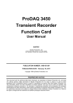
USER MANUAL
ProDAQ VXI Data Acquisition Systems
ProDAQ 3047 Pentium-M based
VXIbus Slot-0 Controller
PUBLICATION NUMBER: 3047-XX-UM-0100
Copyright, © 2014, Bustec Production, Ltd.
Bustec Production, Ltd.
Bustec House, Shannon Business Park, Shannon, Co. Clare, Ireland
Tel: +353 (0) 61 707100, FAX: +353 (0) 61 707106
PROPRIETARY NOTICE
This document and the technical data herein disclosed, are proprietary to Bustec
Production Ltd., and shall not, without express written permission of Bustec
Production Ltd, be used, in whole or in part to solicit quotations from a competitive
source or used for manufacture by anyone other than Bustec Production Ltd. The
information herein has been developed at private expense, and may only be used
for operation and maintenance reference purposes or for purposes of engineering
evaluation and incorporation into technical specifications and other documents,
which specify procurement of products from Bustec Production Ltd. This document
is subject to change without further notification. Bustec Production Ltd. Reserve the
right to change both the hardware and software described herein.
TABLE OF CONTENTS
CHAPTER 1 - INTRODUCTION .......................................................................................... 1
1.1
Overview ............................................................................................................... 1
1.2
Block Diagram ....................................................................................................... 1
1.3
Functional Description ........................................................................................... 3
1.3.1 Central Processor ................................................................................................ 3
1.3.2 Cache Memories .................................................................................................. 3
1.3.3 Chipset ................................................................................................................ 3
1.3.4 SDRAM ................................................................................................................ 4
1.3.5 PCI Busses .......................................................................................................... 4
1.3.6 EIDE Controllers .................................................................................................. 4
1.3.7 USB ..................................................................................................................... 4
1.3.8 PMC Interface ...................................................................................................... 4
1.3.9 Ethernet Controller............................................................................................... 4
1.3.10 Graphics Controller ............................................................................................ 4
1.3.11 Serial Communications ...................................................................................... 5
1.3.12 Keyboard and Mouse ......................................................................................... 5
1.3.13 VXIbus Interface ................................................................................................ 5
CHAPTER 2 - INSTALLATION AND CONFIGURATION ................................................... 7
2.1
Unpacking and Inspection ..................................................................................... 7
2.2
Hardware Configuration ......................................................................................... 8
2.2.1 Logical Address Switch........................................................................................ 8
2.2.2 Opening the Module Enclosure............................................................................ 9
2.2.3 Installing a PMC Module .................................................................................... 10
2.2.4 Installing the ProDAQ 3249 FP I/O Option ........................................................ 13
2.3
Installing the ProDAQ 3047 Controller ................................................................. 14
2.4
Software Configuration ........................................................................................ 15
2.4.1 Configuring the ProDAQ 3047 for the VISA Library ........................................... 15
2.4.2 Configuring the ProDAQ 3047 Interface Characteristics.................................... 18
2.4.3 Running the VXIbus Resource Manager ........................................................... 21
2.4.4 The VISA Assistant ............................................................................................ 23
CHAPTER 3 - PROGRAMMING VXI DEVICES ................................................................ 29
3.1
Connecting to a Device ....................................................................................... 29
3.2
Programming Register-based Devices ................................................................ 30
3.2.1 Accessing Registers .......................................................................................... 30
3.2.2 Moving Blocks of Data ....................................................................................... 33
3.3
Programming Message-based Devices ............................................................... 36
3.3.1 Writing and Reading Messages ......................................................................... 36
3.4
Optimizing Data Throughput ................................................................................ 37
3.5
Using VXIbus and Front Panel Trigger Lines....................................................... 37
3.5.1 Using VXIbus Trigger Lines ............................................................................... 37
3.5.2 Using Front-Panel Trigger Lines ........................................................................ 38
APPENDIX A:
VISA LIBRARY INSTALLATION ............................................................ 41
I
APPENDIX B:
VXIBUS CONFIGURATION REGISTER ................................................ 45
B.1 Address Map and Registers ..................................................................................... 45
B.2 Register Details........................................................................................................ 46
B.2.1 ID Register ........................................................................................................ 46
B.2.2 LogAdr ............................................................................................................... 46
B.2.3 DevType ............................................................................................................ 46
B.2.4 Status ................................................................................................................ 47
B.2.5 Control ............................................................................................................... 48
B.2.6 Offset ................................................................................................................. 48
B.2.7 MODID .............................................................................................................. 48
B.2.8 VMEOffset ......................................................................................................... 49
B.2.9 VXIControl ......................................................................................................... 49
B.2.10 VMEControl ..................................................................................................... 50
B.2.11 EEPROMData ................................................................................................. 50
B.2.12 EEPROMCtrl ................................................................................................... 51
B.2.13 TrigStatus ........................................................................................................ 51
B.2.14 TrigIntMask...................................................................................................... 51
B.2.15 TrigControl....................................................................................................... 53
B.2.16 TrigIntMode ..................................................................................................... 53
B.2.17 IRQDir ............................................................................................................. 54
B.2.18 SerNumHigh .................................................................................................... 54
B.2.19 SerNumLow..................................................................................................... 54
APPENDIX C:
FRONT PANEL CONNECTORS AND SWITCHES ................................ 55
C.1 Front-Panel Connectors........................................................................................... 55
C.1.1 10/100/1000 BaseT Ports ................................................................................. 55
C.1.2 USB ................................................................................................................... 55
C.1.3 RS-232 (COM1/COM2) ..................................................................................... 56
C.1.4 PS2 Combined Keyboard/Mouse Connector..................................................... 56
C.1.5 SVGA Connector............................................................................................... 56
C.1.6 Front-Panel LEDs.............................................................................................. 57
C.1.7 Front-Panel Switches ........................................................................................ 57
C.2 ProDAQ 3249 FP I/O Option ................................................................................... 58
C.2.1 Trigger In/Out...................................................................................................... 58
C.2.2 CLK10 ............................................................................................................... 58
C.2.3 Status LEDs ...................................................................................................... 58
APPENDIX D:
SPECIFICATIONS .................................................................................. 59
D.1 Embedded Controller Characteristics ...................................................................... 59
D.1.1 Processor .......................................................................................................... 59
D.1.2 Memory ............................................................................................................. 59
D.1.3 I/O Ports ............................................................................................................ 59
D.1.4 Graphics Interface ............................................................................................. 59
D.1.5 Hard Disk .......................................................................................................... 59
D.1.6 IEEE P1386.1 PMC Slot ................................................................................... 60
D.2 VXIbus Characteristics ............................................................................................ 60
D.2.1 General ............................................................................................................. 60
D.2.2 VXIbus Master................................................................................................... 60
D.2.3 VXIbus Slave (Configuration Register).............................................................. 60
D.2.4 VXIbus Slave (Shared Memory) ........................................................................ 60
II
D.2.5 VXIbus Requester ............................................................................................. 61
D.2.6 VXIbus Arbiter ................................................................................................... 61
D.2.7 VXIbus Interrupts .............................................................................................. 61
D.2.8 CLK10 Input ...................................................................................................... 61
D.2.9 CLK10 Output ................................................................................................... 61
D.2.10 Trigger In ......................................................................................................... 62
D.2.11 Trigger Out ...................................................................................................... 62
D.3 Power Supply Loading ............................................................................................. 62
D.4 Miscellaneous .......................................................................................................... 62
III
IV
Table of Figures
Figure 1 - ProDAQ 3047 Block Diagram .............................................................................. 2
Figure 2 - Logical Address Switch Location ......................................................................... 8
Figure 3 - Location of Enclosure Screws ............................................................................. 9
Figure 4 - ProDAQ 3047 Module Assembly ....................................................................... 10
Figure 5 - PMC Filler Panel Assembly ............................................................................... 11
Figure 6 - PMC Module Assembly ..................................................................................... 12
Figure 7 - ProDAQ 3249 Assembly .................................................................................... 13
Figure 8 - Installing the ProDAQ 3047 into a C-Size Mainframe ........................................ 14
Figure 9 - VISA Library Configuration Utility ...................................................................... 16
Figure 10 - Adding an Interface ......................................................................................... 16
Figure 11 – Displaying configured Interfaces ..................................................................... 17
Figure 12 - The ProDAQ 3047 Configuration Dialog .......................................................... 18
Figure 13 - Configuring the Interrupt Lines ....................................................................... 20
Figure 14 - Configuring the Front Panel I/O ....................................................................... 21
Figure 15 - Running the VXI Resource Manager ............................................................... 21
Figure 16 - Resource Manager Configuration ................................................................... 22
Figure 17 - The VISA Assistant .......................................................................................... 23
Figure 18 - VISA Assistant Session Window ..................................................................... 23
Figure 19 - Using a template operation .............................................................................. 24
Figure 20 - Using a basic I/O operation ............................................................................. 25
Figure 21 - Memory I/O Operations ................................................................................... 25
Figure 22 - Shared Memory Operations............................................................................. 26
Figure 23 - VXI Specific Operations ................................................................................... 27
Figure 24 - Opening a VISA Session ................................................................................. 29
Figure 25 - Memory-based I/O ........................................................................................... 31
Figure 26 - Register I/O using memory mapping ............................................................... 32
Figure 27 - Moving a Block of Data .................................................................................... 33
Figure 28 - VXIbus transfer types ...................................................................................... 34
Figure 29 - Performing VXIbus Block Transfers ................................................................. 35
Figure 30 - Reading the Device Identification .................................................................... 36
Figure 31 - Sending a Trigger Pulse .................................................................................. 38
Figure 32 - Mapping Trigger Lines ..................................................................................... 40
Figure 33 - Selecting the Type of Installation. .................................................................... 42
Figure 34 - Selecting Components for Installation. ............................................................ 42
Figure 35 - Selecting Installation Options .......................................................................... 43
Figure 36 - Finishing the Setup .......................................................................................... 43
V
VI
Chapter 1 - Introduction
1.1
Overview
The ProDAQ 3047 high-performance Slot-0 Controller provides a powerful, fully
customizable platform for embedded applications. Using Concurrent Technologies
Pentium M Processor Single Board Computer series VP325, and Bustec’s ProDAQ 3040
6U VME64x to C-Size VXIbus adapter, it provides the computational power and bandwidth
for algorithmic- and throughput-intensive control, test and data acquisition applications.
The VP325 Intel Pentium M Processor Single Board Computer provides a powerful, fully
customizable platform for embedded applications with a processor speed of 1.6 GHz. The
Pentium M processor supports the Dual Independent Bus (DIB) architecture with the
backside bus connected to the on-die Level 2 cache and the 64-bit front-side bus
connected to the memory controller at 400 MHz to provide a maximum theoretical transfer
bandwidth of 3.2 Gbytes/second. The processor is capable of addressing 4 Gbytes of
physical memory all of which is cacheable, and 64 Terabytes of virtual memory. The Level
1 (64 Kbytes instructions / 64 Kbytes data) and Level 2 (1 Mbyte instructions and data)
caches are both implemented on the processor die for maximum performance.
The ProDAQ 3040 6U VME64x to C-Size VXIbus Adapter allows the usage of 6U VMEbus
boards in a C-Size VXIbus system. It translates VMEbus cycles into VXIbus cycles and
vice versa. In addition it houses the extensions necessary for VXIbus devices, as there are
the configuration registers, a trigger and extended interrupt interface, MODID support and
the 10 MHz clock generation. It forwards all VME master cycles transparently to the
VXIbus, allowing a VMEbus master the full access to the VXIbus. On the VXIbus it allows
the full integration of the module in the VXIbus resource management by providing a set of
VXIbus compatible configuration registers and a configurable translation window in the
VXIbus A24 or A32 address space. Accesses to this translation window are forwarded to
the VMEbus module’s A16, A24, A32 or CR/CSR space.
Together they provide a powerful C-size, single Slot, register based embedded VXIbus
Slot-0 controller that can to be used as an embedded controller in Slot-0 and non-Slot-0
applications.
1.2
Block Diagram
Figure 1 shows a functional block diagram of the ProDAQ 3047 Pentium-M based VXIbus
Slot-0 controller.
Copyright, © 2006, Bustec Production Ltd.
Page 1 of 62
Chapter 1 - Introduction
Keyboard
Mouse
ProDAQ 3047 User Manual
2xRS232
USB
Graphics
PC87417
Super I/O
2 x Ethernet
(10/100/1000-TX)
PMC Module
Front-Panel I/O
Intel
82546GB
PMC Module
6300ESB
I/O Hub
Hub Link
BIOS
FLASH
On-board
DDR SDRAM
Intel
855GME
Universe II
DDR SDRAM
SO-DIMM
Intel
Pentium-M
optional front-panel CLK10 and Trigger I/O
Internal 2.5”
hard-drive slots
1&2
32-bit PCI bus
64-bit PCI bus
Byte Swap
VXIbus
Configuration
Register
Transparent Cycle
Forwarding
CLK10, Trigger
and MODID
Control
VXIbus Address
Translation
VXIbus
Figure 1 - ProDAQ 3047 Block Diagram
Page 2 of 62
Copyright, © 2006, Bustec Production Ltd.
ProDAQ 3047 User Manual
1.3
Functional Description
The ProDAQ 3047 Pentium-M based VXIbus Slot-0 Controller is a powerful single board
computer based upon the Intel Pentium M processor, an 82546GB dual channel Gigabit
Ethernet controller, the Universe II PCI-to-VMEbus bridge and the 6300ESB I/O hub.
1.3.1 Central Processor
The central processor used on this board is an ultra high performance Intel Pentium-M
processor operating internally at 1.6 GHz. This 32-bit processor supports the Dual
Independent Bus (DIB) architecture with the backside bus connected to the on-die Level 2
cache and the 64-bit frontside bus connected to the memory controller at 400 MHz to
provide a maximum theoretical transfer bandwidth of 3.2 Gbytes/s. The processor is
capable of addressing 4 Gbytes of physical memory all of which is cacheable, and 64
Terabytes of virtual memory.
1.3.2 Cache Memories
The Level 1 and Level 2 caches are both implemented on the processor die for maximum
performance. The Level 1 cache stores 32 Kbytes of instructions and 32 Kbytes of data.
The Level 2 cache stores 1 Mbyte of instructions and data. It operates at the core
frequency and is based on Intel’s Advanced Transfer Cache architecture.
1.3.3 Chipset
The chipset used is comprised of the 855 GME Graphics and Memory Controller Hub and
the 6300ESB I/O Hub.
The 855GME interfaces to the CPU’s host bus. It provides a DDR SDRAM memory
controller, a graphics interface and a high-speed bus to connect to other chipset devices. It
supports concurrent Hub Link and CPU Bus operations.
The 6300ESB provides two PCI busses for supporting high performance PCI devices. The
6300ESB connects to the 855GME via a Hub Link 1.5 interface, which supports a
maximum transfer bandwidth of 266 Mbytes/s.
The 6300ESB also provides a variety of peripheral functions including EIDE controllers,
USB controller, IOAPIC interrupt controller and other legacy PC-AT architectural functions.
The 6300ESB connects to the on-board Firmware HUB containing the BIOS firmware and
to the PC87417 Super I/O controller providing serial ports as well as keyboard and mouse
controller.
Copyright, © 2006, Bustec Production Ltd.
Page 3 of 62
Chapter 1 - Introduction
ProDAQ 3047 User Manual
1.3.4 SDRAM
The 855GME SDRAM controller provides a DDR333 channel to provide a maximum
transfer bandwidth of 2.66 Gbytes/s and features ECC data protection. Up to 1 Gbyte of
on-board memory plus up to 1 Gbyte of SO-DIMM memory is supported.
1.3.5 PCI Busses
There are two on-board PCI busses provided by the 6300ESB I/O controller hub. The
primary PCI bus is 64-bit wide, operates at 33 or 66 MHz and connects to the Gigabit
Ethernet interfaces and the PMC site. The secondary bus is 32-bit wide and connects to
the Universe II™ PCI-to-VMEbus bridge.
1.3.6 EIDE Controllers
The 6300ESB I/O hub provides two EIDE/Ultra ATA100 interfaces. One interface is routed
via the P2 connector to the 2.5” hard drive slot on the ProDAQ 3040 adapter, while the
other one can be used via an on-board connector to directly install either a 2.5” hard-drive
or a CompactFlash carrier.
1.3.7 USB
One USB2.0 port of the 6300ESB I/O hub is available via a front-panel connector.
1.3.8 PMC Interface
A PMC interface, which supports single-width 64-bit or 32-bit PMC modules complying
with the IEEE 1361.1 standard, is provided. Both 5V and 3.3V PCI signaling environments
are supported for 33MHz modules.
1.3.9 Ethernet Controller
A 82546GB Gigabit Ethernet controller is used to provide two high-performance PCI to
Ethernet interfaces. Both support 10 Mbits/s, 100 Mbits/s and 1000 Mbits/s operation via
front-panel RJ45 connectors.
1.3.10 Graphics Controller
The 855GME provides a high-performance graphics accelerator with up to 64 Mbytes of
UMA memory. An analog CRT interface is provided via a 15-pin high-density D-Type
connector on the front panel.
Page 4 of 62
Copyright, © 2006, Bustec Production Ltd.
ProDAQ 3047 User Manual
1.3.11 Serial Communications
The 6300ESB I/O hub provides two RS232 serial data communication channels via two
front-panel RJ45 connectors.
1.3.12 Keyboard and Mouse
A PS/2 type keyboard and mouse interface is available via a 6-way combined Mini-DIN
front-panel connector.
1.3.13 VXIbus Interface
A Tundra Universe II PCI-to-VME bridge provides the VXIbus interface. Additional
hardware byte-swappingand VXIbus address range mapping are implemented through
high-speed programmable logic devices. The ProDAQ 3047 automatically detects whether
he is placed in slot 0 (the leftmost slot in a VXIbus mainframe) and enables or disables the
CLK10 and MODID lines accordingly.
Copyright, © 2006, Bustec Production Ltd.
Page 5 of 62
Chapter 1 - Introduction
Page 6 of 62
ProDAQ 3047 User Manual
Copyright, © 2006, Bustec Production Ltd.
Chapter 2 - Installation and Configuration
To set up and use the ProDAQ 3047 Pentium-M based VXIbus Slot-0 Controller you need
the following:
A VXI mainframe
The ProDAQ 3047 VXIbus Slot-0 Controller
A VGA monitor
PS/2 or USB Keyboard and Mouse
The ProDAQ 3047 VXIbus Slot-0 Controller is a single-slot wide, C-size VXI module, which
can reside in any slot of a C-size or D-size VXI mainframe. It will automatically detect
whether it is located in the left most slot of the mainframe (slot “0”) and will enable or
disable its Slot-0 capabilities accordingly, avoiding conflicts with the backplane and other
modules.
Note
Being a C-size module, the ProDAQ 3047 does not provide a P3 connector as used
in D-size mainframes. If used as a Slot-0 Controller in a D-size mainframe, it cannot
provide the necessary control for instruments using the additional features of the
P3 connector (CLK100, Star Trigger, add. Trigger and Local Bus Lines).
2.1
Unpacking and Inspection
All ProDAQ modules are shipped in an antistatic package to prevent any damage from
electrostatic discharge (ESD). Proper ESD handling procedures must always be used
when packing, unpacking or installing any ProDAQ module, ProDAQ plug-in module or
ProDAQ function card:
Ground yourself via a grounding strap or similar, e.g. by holding to a grounded
object.
Remove the ProDAQ module from its carton, preserving the factory packaging
as much as possible.
Discharge the package by touching it to a grounded object, e.g. a metal part of
your VXIbus chassis, before removing the module from the package.
Inspect the ProDAQ module for any defect or damage. Immediately notify the
carrier if any damage is apparent.
Only remove the module from its antistatic bag if you intend to install it into a VXI
mainframe or similar.
When reshipping the module, use the original packing material whenever possible. The
original shipping carton and the instrument’s plastic foam will provide the necessary
support for safe reshipment. If the original anti-static packing material is unavailable, wrap
the ProDAQ module in anti-static plastic sheeting and use plastic spray foam to surround
and protect the instrument.
Copyright, © 2006, Bustec Production Ltd.
Page 7 of 62
Chapter 2 - Installation and Configuration
2.2
ProDAQ 3047 User Manual
Hardware Configuration
In general, the ProDAQ 3047 does not need to be configured to be able to run in your
VXIbus mainframe other then by choosing the logical address and the slot it will be
installed in. It will automatically detect whether it is located in left most slot of the
mainframe (slot “0”), and enable or disable the system controller and slot-0 capabilities
accordingly.
All other hardware configuration settings are set to their defaults, which will be sufficient for
running the ProDAQ 3047 in most applications and environments. However, if you want for
example to install a PMC module, you may need to change some settings as described
below.
2.2.1 Logical Address Switch
Figure 2 shows the location of the logical address switch on the ProDAQ 3047. Set each
switch to ‘Off’ for a logical one (1) and to ‘On’ for a logical zero (0). The picture shows the
address switch set to logical address zero (0).
Figure 2 - Logical Address Switch Location
1
2
3
4
5
6
7
8
Off
On
If the ProDAQ 3047 is used in a non-slot-0 position, it can be either statically or
dynamically configured. To configure it statically, the logical address switch must be set to
a value between 1 and 254. This determines the logical address of the module
permanently and can only be altered by changing the setting of the logical address switch.
To configure the ProDAQ 3047 dynamically, the logical address switch must be set to 255.
The resource manager will use the VXIbus MODID lines to access and configure the
board, and assigns a logical address during run-time.
Note
To be able to act as the Slot-0 Controller AND the Resource Manager for the VXI
mainframe it is installed in, the ProDAQ 3047 must be located in the left most slot
(slot “0”) of the VXI mainframe AND must be configured to use the logical address
0 (00hex).
Page 8 of 62
Copyright, © 2006, Bustec Production Ltd.
ProDAQ 3047 User Manual
2.2.2 Opening the Module Enclosure
To install a PMC module or the ProDAQ 3249 FP I/O option in the PMC slot of the
ProDAQ 3047, you will need to remove both the top and bottom cover of the metal
enclosure. To do so, you will have to remove the seven screws holding the enclosure in its
place:
1. a M2.5x6mm undercut flathead screw from the back of the module,
2. two M2.5x25mm panhead screws connecting the top an bottom cover
through the ProDAQ 3040 PCB,
3. two M2.5x6mm panhead screws connecting the top cover to the frontpanel mounting blocks,
4. and two M2.5x8mm panhead screws connecting the bottom cover, the
VP325 PCB and the extraction handles to the front-panel mounting
blocks.
The following picture shows the location of the different screws:
Figure 3 - Location of Enclosure Screws
The covers are also held in place by four cover hooks each, two per side. After removing
the screws, you will need to remove the covers by sliding them back and up (down for the
bottom cover) at the same time.
Copyright, © 2006, Bustec Production Ltd.
Page 9 of 62
Chapter 2 - Installation and Configuration
ProDAQ 3047 User Manual
Figure 4 - ProDAQ 3047 Module Assembly
2.2.3 Installing a PMC Module
Page 10 of 62
Copyright, © 2006, Bustec Production Ltd.
ProDAQ 3047 User Manual
The ProDAQ 3047 provides one slot to install a PMC module. To install a PMC module,
you must first remove the PMC filler panel, which covers the front-panel PMC cutout in
case no PMC module is installed.
Figure 5 - PMC Filler Panel Assembly
To remove the filler panel, unscrew the two M2.5x6mm panhead screws connecting it to
the printed circuit board below (see Figure 5 - PMC Filler Panel Assembly). In case your
ProDAQ 3047 has the ProDAQ 3249 Front-panel I/O option installed, you will need to
remove it in the same way, as it takes the place of a PMC card when installed (see also
2.2.4 : Installing the ProDAQ 3249 FP I/O Option).
The ProDAQ 3047 PMC slot supports both the 3.3V and 5V signaling environment defined
in the PCI standard. For setting the correct voltage for your PMC module, you need to
install the detachable polarizing key for the PMC module in the correct location and set an
on-board jumper.
Caution
If the PMC V(I/O) configuration selected does not match the PMC modules
requirements, it may result in damage to the module or to the ProDAQ 3047.
The polarization key is located in the middle of the PMC slot either between or in front of
the four PMC bus connectors (Pn1/Jn1 to Pn4/Jn4). Choose the position in front of the
connectors for the 3.3V signaling environment and the position right between the
Copyright, © 2006, Bustec Production Ltd.
Page 11 of 62
Chapter 2 - Installation and Configuration
ProDAQ 3047 User Manual
connectors for the 5V signaling environment. The jumper for the V(I/O) selection is located
besides the PMC slot and must be set to 1-2 to select 3.3V and to 2-3 to select 5V:
Figure 6 - PMC Module Assembly
To install the PMC module, insert it first into the front-panel cutout (1) and then press it
down (2) until the PMC connectors Pn1/Jn1 to Pn4/J4 are seated correctly. Fix the PMC
module on the board using four M2.5x6mm screws as shown in Figure 6.
Note
Due to the utilization of the outer rows of the backplane bus connectors on the
VXIbus, the ProDAQ 3047 does not support any form of rear-panel I/O via the PMC
bus connector Pn4/Jn4.
The ProDAQ 3047 supports the automatic switching between 33MHz and 66MHz PCI bus
speed depending on the installed PMC module. If necessary, the speed can also be fixed
to 33Mhz by setting the switch SW4, position 1 to “on”. The switch is located on the solder
site of the module.
Note
When the PCI bus speed for the PMC module is set fixed to 33Mhz, the dual
Ethernet controller sitting on the same PCI bus segment will also be restricted to
33Mhz bus speed.
Page 12 of 62
Copyright, © 2006, Bustec Production Ltd.
ProDAQ 3047 User Manual
2.2.4 Installing the ProDAQ 3249 FP I/O Option
To allow access to the VXIbus trigger lines and the VXIbus CLK10 clock signal, the
ProDAQ 3249 Front-panel I/O option can be installed in the PMC slot. It provides the
connectors for the front-panel trigger I/O and VXIbus CLK10 and houses two LEDs
showing the status of the VXIbus SYSFAIL* signal and any activity on the VXIbus.
Note
The ProDAQ 3249 Front-Panel I/O Option cannot be installed together with a PMC
module, as it is located in the PMC slot. If your application requires access to the
VXIbus trigger lines or the VXIbus CLK10 signal AND you need to utilize a PMC
card in the controller, please contact Bustec Production Ltd. for other options of
providing those signals.
To install the ProDAQ 3249, remove the PMC filler panel, place the 3249 in the front-panel
cutout and connect the flat cable attached to it into the connector on the ProDAQ 3040
board. Fix the 3249 with two M2.5 x 6mm screws to the PCB.
Figure 7 - ProDAQ 3249 Assembly
The routing of the VXIbus CLK10 signal can be defined via the VISA library configuration
tool (see 2.4.2.3). The routing of the VXIbus trigger signals to/from the front-panel I/O can
be configured by your application using the standard VISA functions viMapTrigger and
viUnmapTrigger.
Copyright, © 2006, Bustec Production Ltd.
Page 13 of 62
Chapter 2 - Installation and Configuration
2.3
ProDAQ 3047 User Manual
Installing the ProDAQ 3047 Controller
To prevent damage to the ProDAQ module being installed, it is recommended to remove
the power from the mainframe or to switch it off before installing.
Insert the module into the mainframe using the guiding rails inside the mainframe as
shown in Figure 8. Push the module slowly into the slot until the modules backplane
connectors seat firmly in the corresponding backplane connectors. The top and bottom of
the front panel of the module should touch the mounting rails in the mainframe.
Figure 8 - Installing the ProDAQ 3047 into a C-Size Mainframe
Note:
To ensure proper grounding of the module, tighten the front panel mounting
screws after installing the module in the mainframe.
Connect your monitor, keyboard and mouse to the respective front-panel connectors. If
you are using both keyboard and mouse using the PS/2 connector, you will need to use
the PS/2 splitter cable coming with the ProDAQ 3047.
Page 14 of 62
Copyright, © 2006, Bustec Production Ltd.
ProDAQ 3047 User Manual
2.4
Software Configuration
The ProDAQ 3047 comes with the operating system pre-installed on the internal hard disk
drive. When you boot the ProDAQ 3047 for the first time, the Windows Welcome or MiniSetup is started to help you finalizing your computers configuration. You will be asked to
complete the settings for
License Key
Computer Name
Administrator Password
Domain Settings
Time Zone
User Accounts
etc.
The exact sequence depends on the chosen operating system version.
When prompted to enter your license key, please use the information from the license
documents coming with your ProDAQ 3047.
The VISA library, the VXI resource manager and all tools are already pre-installed as well.
You will find shortcuts to all programs in the VXIPNP group of your start menu. In case you
want to update the VISA library installation later on, please refer to Appendix A: Visa
Library Installation.
2.4.1 Configuring the ProDAQ 3047 for the VISA Library
The VISA library uses interface names and numbers to access available hardware
interfaces. In order to enable the VISA library to use the ProDAQ 3047 VXIbus interface,
you must run the VISA configuration once to ensure that an active configuration for the
VXIbus interface of the 3047 is stored.
From the VXIplug&play program group created during the installation of the VISA library,
select “VISA Configuration Utility” (“Start” “VXIPNP” “VISA Configuration Utility”).
This will start the configuration tool for the VISA library and attached hardware interfaces.
Copyright, © 2006, Bustec Production Ltd.
Page 15 of 62
Chapter 2 - Installation and Configuration
ProDAQ 3047 User Manual
Figure 9 - VISA Library Configuration Utility
To add a new interface, select “Add Interfaces”. A new dialog “Available Interfaces” is
shown with a list of unconfigured devices found in the system. The VXIbus interface of the
ProDAQ 3047 appears as interfaces of the type “VXI” together with a description
containing the serial number of the device.
Figure 10 - Adding an Interface
To add the VXIbus interface of the ProDAQ 3047, select the entry for the device in the list,
choose an interface number on the right side and select ‘OK’. The list of configured
interfaces in the main dialog will now display the configured interface with its interface
name and number.
Page 16 of 62
Copyright, © 2006, Bustec Production Ltd.
ProDAQ 3047 User Manual
Figure 11 – Displaying configured Interfaces
To remove an interface from the system, select the device in the list of configured
interfaces and select “Remove Interface”. To configure device-dependent parameters of
an interface, select “Configure Interface”.
Copyright, © 2006, Bustec Production Ltd.
Page 17 of 62
Chapter 2 - Installation and Configuration
ProDAQ 3047 User Manual
2.4.2 Configuring the ProDAQ 3047 Interface Characteristics
The VXIbus interface of the ProDAQ 3047 has a number of characteristics that can be
configured with the configuration utility. The settings are stored together with the device
name/number and the serial number on the system and applied whenever the resource
manager is executed.
To configure the ProDAQ 3047, select the interface in the list and click “Configure
Interface”. The four tab panels of the configuration dialog allow to configure the different
parts of the interface:
VXIbus
Interrupt
Front-End
Configures various parameters used by the ProDAQ 3047
when accessing the VXIbus.
Configures the assignment and use of the VXIbus interrupt
lines.
Configures the routing of VXIbus clock and trigger lines
to/from the front panel connectors.
Figure 12 - The ProDAQ 3047 Configuration Dialog
To store the altered configuration, select “OK”. “Cancel” closes the dialog without altering
the stored configuration.
NOTE
To apply changes to the configuration of the 3047, you will need to re-run the
resource manager or to restart your VXI mainframe to make these changes
effective.
Page 18 of 62
Copyright, © 2006, Bustec Production Ltd.
ProDAQ 3047 User Manual
.
2.4.2.1 Configuring the VXIbus Access
To configure the VXIbus access of the ProDAQ 3047, select the tab “VXIbus” in the
configuration dialog window (see Figure 12). The configurable parameters are:
Bus Time-out
Arbitration Mode
Arbiter Time-out
Request Mode
Request Level
Release Mode
The time the on-board times needs to expire once a
VXIbus access by the 3020 is started. If it expires, a
VXIbus slave did not respond correctly and a bus error is
generated.
Possible values are: Disabled, 16 µsec, 32 µsec, 64 µsec,
128 µsec, 256 µsec, 512 µsec and 1024 µsec.
Selects the bus arbiter mode. Possible values are:
“Priority”, “Single Level Arbitration” or “Round Robin”.
(Remark: The arbiter is only enabled if the module is
placed in the leftmost slot of a VXI mainframe, slot “0”).
Selects the time-out for the bus arbiter.
Sets the request mode of the ProDAQ 3020, “Fair” or
“Demand”.
Selects the request level the module is using when
accessing the VXIbus. Possible values are 3 to 0, with 3
as the highest priority and 0 as the lowest.
Selects the release mode: “RWD” (release when done) or
“ROR” (release on request).
2.4.2.2 Configuring the Interrupt Lines
The configuration tool allows configuring the usage of the VXIbus interrupt lines in
the allocation mechanism of the VXI resource manager.
To configure the lines, select the tab “Interrupt” in the configuration dialog window.
For each of the VXIbus interrupt lines (Level 1 to Level 7) one of two settings for the
assignment can be chosen (see Figure 13):
Auto
None
This setting will allow the resource manager to use the interrupt line
for this level in his allocation mechanism.
This setting will prevent the resource manage to use the interrupt line
for this level in his allocation mechanism. This setting must be used if
a instrument in the system does not allow the dynamic allocation of
interrupt lines and wants to use one or more lines permanently
allocated.
Copyright, © 2006, Bustec Production Ltd.
Page 19 of 62
Chapter 2 - Installation and Configuration
ProDAQ 3047 User Manual
Figure 13 - Configuring the Interrupt Lines
2.4.2.3 Configuring the Front Panel I/O
The ProDAQ 3047 Slot-0 Controller supports the synchronization of multi-mainframe
systems via shared system clocks (CLK10) and trigger lines. These lines are
available via the ProDAQ 3249 FP I/O option when installed in the PMC slot of the
3047. To configure the front panel input and output signals, select the “Front Panel
I/O” tab on the right hand side of the configuration utility window (see Figure 14).
If the ProDAQ 3047 is located in the left most slot (slot “0”) of a VXIbus mainframe, it
can be configured to either receive a CLK10 signal via the “CLK10” connector or to
generate a CLK10 signal internally and share it with other mainframes via the
“CLK10” connector on the 3249. The “Front Panel CLK10 I/O” control allows you to
configure this:
Disabled
The ProDAQ 3047 uses the internal clock generator to
generate the CLK10 clock signal for the VXIbus. The
front-panel CLK10 I/O is disabled.
Enabled as Output
The ProDAQ 3047 uses the internal clock generator to
generate the CLK10 clock signal for the VXIbus and
additionally makes the clock signal available via the front
panel “Clk Out” connector.
Enabled as Input
The internal clock generator is disabled and the ProDAQ
3047 uses the clock signal from the “Clk In” connector to
generate the VXIbus CLK10 clock signal.
If the module is located in any other slot in a VXIbus system, the CLK10 signal
supplied by the VXIbus is used.
Page 20 of 62
Copyright, © 2006, Bustec Production Ltd.
ProDAQ 3047 User Manual
Figure 14 - Configuring the Front Panel I/O
The actual mapping of the “Trig In” signal to one or many of the VXIbus trigger lines and
the mapping of the VXIbus trigger line or lines to the “Trig Out” signal is done using VISA
functions (see 3.5.2 : Using Front-Panel Trigger Lines).
2.4.3 Running the VXIbus Resource Manager
Before you can use the VISA library to communicate to the instruments, you must run the
resource manager. The resource manager searches for VXI and GPIB instruments
connected to your PC and configure them. To run the resource manager, select “VXIbus
Resource Manager” from the VXIplug&play program group in the start menu (“Start”
“VXIPNP” ”VXI Resource Manager”).
Figure 15 - Running the VXI Resource Manager
After start, the resource manager will wait a defined time to allow all devices to complete
their initialization and self-test (if available). Then he performs the following functions:
Copyright, © 2006, Bustec Production Ltd.
Page 21 of 62
Chapter 2 - Installation and Configuration
1.
2.
3.
4.
5.
6.
ProDAQ 3047 User Manual
Identify all VXIbus and GPIB devices in the system.
Manage the system self-test and diagnostic sequence.
Configure the system’s A24 and A32 address maps.
Configure the system’s Commander/Servant hierarchies.
Allocate the VXIbus IRQ lines.
Initiate normal system operation.
Once finished, the information about the VXIbus and GPIB devices found is made
available for the VISA library and a readable version of this information is saved to a file.
Both the initial delay and the location of the resource manager output file are configurable
using the configuration utility.
To configure these parameters, start the configuration utility by selecting the “VISA
Configuration Utility” entry in the VXIplug&play program group in the start menu (“Start”
“VXIPNP” ”VISA Configuration Utility”). In the configuration utility, select the “Resource
Manager” button on the right hand side (see Figure 9). This will show the configuration
dialog for the resource manager, which allows configuring the output file destination and
initial delay.
Figure 16 - Resource Manager Configuration
Caution
The initial resource manager delay as defined by the VXIbus standard must be in
minimum five (5) seconds. Configuring the resource manager to use a shorter delay
might not allow all devices to finish their initialization and self-test, preventing the
resource manager from identifying and configuring them.
Note
The VISA library is a shared library that initializes itself when it is first loaded by an
application. Applications started while the VISA library is already loaded just share
this configuration. Only when all applications using the VISA library are stopped, it
will be unloaded by the system. Therefore all applications using the VISA library
must be closed before running the resource manager or using the VISA
configuration utility. Take special care while using integrated development
environments, they will keep the VISA library loaded even when the application
developed in them was stopped.
Page 22 of 62
Copyright, © 2006, Bustec Production Ltd.
ProDAQ 3047 User Manual
2.4.4 The VISA Assistant
The VISA Assistant is an interactive tool, which allows executing VISA commands without
programming. To run the VISA Assistant, select “VISA Assistant” from the VXIplug&play
program group in the start menu (“Start” “VXIPNP” ”VISA Assistant”).
The main window of the Visa Assistant shows a list of all VISA resources in the system:
Figure 17 - The VISA Assistant
On selecting one by double-clicking on its entry, the VISA Assistant opens a VISA session
for that device in a separate window:
Figure 18 - VISA Assistant Session Window
In the treeview control on the left hand side you have now access to information about the
session and the VISA functions possible for the resource.
Copyright, © 2006, Bustec Production Ltd.
Page 23 of 62
Chapter 2 - Installation and Configuration
ProDAQ 3047 User Manual
The functions available are divided into five groups:
Template Operations
Basic I/O Operations
Memory I/O Operations
Shared Memory Operations
VXI Specific Operations
Not all operations are available for all types of devices, so depending on the device type,
the treeview control might not list all the possibilities discussed here.
2.4.4.1 Template Operations
The VISA standard implements a template of standard services for a resource. The
functions in this group provide access to those services. The services available include
attribute operations, asynchronous operation control, resource access control and event
operations.
As an example, the function viGetAttribute allows to retrieve the values for attributes
defined for a resource. Selecting the function in the treeview control on the left hand side
(click on “Template Operations”, then on “viGetAttribute”) allows you to control the
parameters for the function in a dialog on the right hand side of the session window:
Figure 19 - Using a template operation
Select one of the attributes to retrieve in the “Attribute” control in the “Input” section and
press “Run”. The “Output” section will show the current value of the attribute in the control
“Attribute state”, if the operation was successful, and the returned status of the function.
2.4.4.2 Basic I/O Operations
The basic I/O operations will allow the user to send commands to a device and read back
its answer, to trigger the device or read its status.
Page 24 of 62
Copyright, © 2006, Bustec Production Ltd.
ProDAQ 3047 User Manual
Figure 20 - Using a basic I/O operation
As an example, you can use the viRead function to read data or a message from the
device. To do so, just specify the maximum number of bytes to read from the device and
press “Run”. As before, the VISA Assistant will show the message read as well as the
returned status of the operation.
2.4.4.3 Memory I/O Operations
The memory I/O operations consist of High- and Low-Level Access services. The HighLevel Access Services allow register-level access to devices that support direct memory
access. They encapsulate most of the code required to perform the access, such as
window mapping, address translation and error checking. The Low-Level Access Services
are similar in purpose, but are implemented without the software overhead of the HighLevel Services.
Figure 21 - Memory I/O Operations
Copyright, © 2006, Bustec Production Ltd.
Page 25 of 62
Chapter 2 - Installation and Configuration
ProDAQ 3047 User Manual
Figure 21 shows an example of the high-level access services. In the “Input” section the
user can select an address space, an offset and a transfer width. By pressing “Run”, on of
the functions viIn8, viIn16 or viIn32 (depending on the access width) are executed and the
result is shown in the “Output” section of the dialog along with the returned status.
The high-level functions viMoveIn, viMoveOut and viMoveAsync will move blocks of data.
As with the functions viIn8, vIn16, viIn32, viOut8, viOut16 and viOut32, the “Input” section
will allow you to enter an address space, an offset and a transfer width. Additionally a
length parameter will define the number of elements to transfer.
The low-level access services viMapAddress, viUnmapAddress, viPeek and viPoke need
to be used together. First a memory mapping must be established by using the function
viMapAddress, then viPeek and viPoke can be used to access the mapped register space,
and viUnmapAddress must be used to undo the memory mapping.
2.4.4.4 Shared Memory Operations
Shared memory operations allow to allocate memory space on the device to be used
exclusively by the session allocating it. Figure 22 shows an example of the shared memory
operations.
Figure 22 - Shared Memory Operations
2.4.4.5 VXI Specific Operations
VXI Specific Operations are those operations, which were implemented to deal with
special circumstances you can find only on controller and instruments using the VXIbus to
communicate. The example shows an operation, which can be found only for backplane
resources of VXIbus mainframes (see Figure 23).
Page 26 of 62
Copyright, © 2006, Bustec Production Ltd.
ProDAQ 3047 User Manual
Figure 23 - VXI Specific Operations
The functions viMapTrigger and viUnmapTrigger enable you to route a trigger signal from
a front panel input to one of the VXIbus trigger lines (only for VXIbus controller supporting
this feature). In the “Input” section you can select a source trigger line, which should be
mapped to a destination trigger line. As in the other examples, pressing “Run” will execute
the function and display the result in the “Output” section.
Note
For more information about the VISA functions and their parameter, refer to the
VXIplug&play Systems Alliance document “VPP-4.3: The VISA Library”.
Copyright, © 2006, Bustec Production Ltd.
Page 27 of 62
Chapter 2 - Installation and Configuration
Page 28 of 62
ProDAQ 3047 User Manual
Copyright, © 2006, Bustec Production Ltd.
Chapter 3 - Programming VXI Devices
This chapter shows how to use the ProDAQ 3047 Embedded VXIbus Slot-0 Controller and
the Bustec VISA library to program VXI instruments.
3.1
Connecting to a Device
An application using the VISA library to communicate with the instrument needs to open a
session for the resource it wants to use. A resource might be a physical resource as for
example a VXI instrument or a virtual resource like the backplane or the resource
manager. The session will handle all accesses, attributes and services for the particular
resource.
#include <visa.h>
main (int argc, char **argv)
{
ViStatus status;
ViSession rm_session;
ViSession instr_session;
ViChar descr[256];
/* open a session to the resource manager */
if ((status = viOpenDefaultRM (&rm_session)) != VI_SUCCESS)
{
viStatusDesc (rm_session, status, descr);
if (status > VI_SUCCESS)
printf (“VISA WARNING: viOpenDefaultRM returned status %08x (%s)\n”,
status, descr);
else
{
printf (“VISA ERROR: viOpenDefaultRM returned status %08x (%s)\n”,
status, descr);
return status;
}
}
/* open a session to the instrument */
if ((status = viOpen (rm_session, “VXI0::2::INSTR”,
VI_NULL, VI_NULL, &instr_session)) != VI_SUCCESS)
{
viStatusDesc (instr_session, status, descr);
if (status > VI_SUCCESS)
printf (“VISA WARNING: viOpen returned status %08x (%s)\n”,
status, descr);
else
{
printf (“VISA ERROR: viOpen returned status %08x (%s)\n”,
status, descr)
return status;
}
}
/* accessing the instrument */
/* close the sessions to the instrument and the resource manager */
viClose (instr_session);
viClose (rm_session);
}
Figure 24 - Opening a VISA Session
The example shown in Figure 24 contains all necessary steps to connect to a device using
VISA functions. The first step in a program, which uses the VISA library, is always to open
Copyright, © 2006, Bustec Production Ltd.
Page 29 of 62
Chapter 3 - Programming VXI Devices
ProDAQ 3047 User Manual
a session to the default resource manager (). It provides connectivity to all VISA
resources registered with it and gives applications control and access to individual
resources.
The next step is to open a session to the instrument or multiple sessions to multiple
instruments (). The resource name used is a combination of interface type and number,
logical address of the VXI device, and a device type:
VXI 0 :: 2 :: INSTR
Interface Type
Interface Number
Device Type
Logical Address
The interface type for the ProDAQ 3047 Slot-0 Controller is always “VXI”. The interface
number is the number, which was assigned to the particular 3047 by using the VISA
configuration utility (see 2.4.1 : Configuring the ProDAQ 3047 for the VISA Library). The
logical address of a VXI device is defined either statically by setting its logical address
switch, or dynamically during runtime by the resource manager. If the resource manager
assigned the address dynamically, the actual assignment can be found in the output file of
the resource manager (see 2.4.3 - Running the VXIbus Resource Manager). The device
type for VXI instruments is always “INSTR”.
Note
When running the above example, please make sure that the logical address used
in it matches the logical address setting of the instrument you want to connect to.
Note
Before you can use the above example to connect to your device, you must run the
VXI Resource Manager (see 2.4.3 : Running the VXIbus Resource Manager).
3.2
Programming Register-based Devices
Register-based devices are devices implementing a set of registers in A16 and often in
A24 or A32. Programming register-based devices is done by reading and writing these
registers to change their contents, either by bit, in groups of bits or in whole.
3.2.1 Accessing Registers
To access single registers, the VISA library offers two groups of functions. The first group,
viIn8, viIn16, viIn32, viOut8, viOut16, viOut32, provides a standardized, single word
access to a device register in A16, A24 or A32 space. Figure 25 shows an example of a
function reading a value from a device register (), modifying the value read and writing it
back (). The driver for the ProDAQ 3047 will automatically take care about byte ordering,
i.e. it will swap the words to be read or written between the little-endian host byte ordering
your PC is using to the big-endian byte ordering used on the VXIbus.
Page 30 of 62
Copyright, © 2006, Bustec Production Ltd.
ProDAQ 3047 User Manual
ViStatus function rmw_register (ViSession instr_session, ViBusAddress offset, ViUInt16 mod)
{
ViStatus status;
ViChar descr[256];
ViUInt16 value;
if ((status = viIn16 (instr_session, VI_A16_SPACE, offset, &value) != VI_SUCCESS)
{
viStatusDesc (instr_session, status, descr);
if (status
printf
else
{
printf
return
}
> VI_SUCCESS)
(“VISA WARNING: viIn16 returned status %08x (%s)\n”, status, descr);
(“VISA ERROR: viIn16 returned status %08x (%s)\n”, status, descr);
status;
}
value = value | mod;
if ((status = viOut16 (instr_session, VI_A16_SPACE, offset, value) != VI_SUCCESS)
{
viStatusDesc (instr_session, status, descr);
if (status
printf
else
{
printf
return
}
> VI_SUCCESS)
(“VISA WARNING: viOut16 returned status %08x (%s)\n”, status, descr);
(“VISA ERROR: viOut16 returned status %08x (%s)\n”, status, descr);
status;
}
return VI_SUCCESS;
}
Figure 25 - Memory-based I/O
The second group of functions is intended to map a register range into the memory of the
host and accessing it directly. Because this ability is architecture and system dependent,
the VISA standard foresees an attribute, which allows determining whether the range
could be physically mapped or the system architecture does not allow it. Depending on the
value of the attribute VI_ATTR_WIN_ACCESS, the range mapped can be directly
accessed (e.g. by using a C-style pointer), or the functions viPeek8, viPeek16, viPeek32,
viPoke8, viPoke16 and viPoke32 must be used to access registers in the mapped range.
Figure 26 shows the same function as in Figure 25, this time implemented with memory
mapping functions.
Copyright, © 2006, Bustec Production Ltd.
Page 31 of 62
Chapter 3 - Programming VXI Devices
ProDAQ 3047 User Manual
ViStatus function rmw_register (ViSession instr_session, ViBusAddress offset, ViUInt16 mod)
{
ViStatus status;
ViChar descr[256];
ViAddr address;
ViUInt16 win_access;
ViUInt16 value;
(instr_session, VI_A32_SPACE, offset,
if ((status = viMapAddress
sizeof (ViUInt16), VI_FALSE, (ViAddr) 0, &address)) != VI_SUCCESS)
{
viStatusDesc (instr_session, status, descr);
if (status > VI_SUCCESS)
printf (“VISA WARNING: viMapAddress returned status %08x (%s)\n”,
status, descr);
else
{
printf (“VISA ERROR: viMapAddress returned status %08x (%s)\n”,
status, descr);
return status;
}
}
(instr_session,
if ((status = viGetAttributeVI_ATTR_WIN_ACCESS,
&win_access)) != VI_SUCCESS)
{
viStatusDesc (instr_session, status, descr);
if (status > VI_SUCCESS)
printf (“VISA WARNING: viGetAttribute returned status %08x (%s)\n”,
status, descr);
else
{
printf (“VISA ERROR: viGetAttribute returned status %08x (%s)\n”,
status, descr);
return status;
}
}
if (win_access == VI_DEREF_ADDR)
{
/* allowed to use pointer or similar */
value = *((ViUInt16 *) address);
value = value | mod;
*((ViUInt16 *) address) = value;
}
else if (win_access == VI_USE_OPERS)
{
/* use functions to access memory */
viPeek16 (instr_session, address, &value);
value = value | mod;
viPoke16 (instr_session, address, value);
}
if{ ((status = viUnmapAddress (instr_session) != VI_SUCCESS)
viStatusDesc (instr_session, status, descr);
if (status > VI_SUCCESS)
printf (“VISA WARNING: viUnmapAddress returned status %08x (%s)\n”,
status, descr);
else
{
printf (“VISA ERROR: viUnmapAddress returned status %08x (%s)\n”,
status, descr);
return status;
}
}
return VI_SUCCESS;
}
Figure 26 - Register I/O using memory mapping
Page 32 of 62
Copyright, © 2006, Bustec Production Ltd.
ProDAQ 3047 User Manual
In the above example, the function viMapAddress is used to map a register range starting
with offset and extending over the size of the register into the memory of the host (). If
this is successful, the attribute “VI_ATTR_WIN_ACCESS” is checked to see whether the
controller was able to map the address range physically into the memory space of the
controller, or whether the mapping was done only logically (). If the mapping was done
physically, the application is allowed to use the address, the register range is mapped to,
as if it is accessing its own memory. So for example C-style pointers may be used to
change the register value (). If the mapping was done only logically, the application need
to use the functions viPeek and viPoke provided by the VISA library to access the mapped
register range (). The VISA library will use the stored values for the mapped offset and
range to calculate the physical address and execute a single access in the same way as
internally done for the high-level functions. The function viUnmapAddress must be used to
undo the mapping of the register range (). Only one mapping per session is allowed by
the VISA standard. Please not that the functions viPeek and viPoke will work in both cases
(VI_ATTR_WIN_ACCESS equal to VI_DEREF_ADDR or equal to VI_USE_OPERS), but
will introduce a slightly higher overhead then using direct access if possible.
3.2.2 Moving Blocks of Data
To move blocks of data between an instruments memory and the host memory, the VISA
library implements the functions viMoveIn and viMoveOut for different transfer sizes. In
addition a number of attributes can be used to define the type of transfer performed on the
VXIbus.
#include <visa.h>
/* buffer used to store data from the instrument */
ViUInt16 data[1024];
main (int argc, char **argv)
{
ViStatus status;
ViSession rm_session;
ViSession instr_session;
ViChar descr[256];
ViUInt16 value;
/* open a session to the resource manager and instrument
* as shown in Figure 24 - Opening a VISA Session (not shown here) */
. . . .
/* now move a block of 16-bit data from the instrument to the buffer */
if ((status = viMoveIn16 (instr_session,
VI_A32_SPACE, MEM_START, 1024, data) != VI_SUCCESS)
{
viStatusDesc (instr_session, status, descr);
if (status
printf
else
{
printf
return
}
> VI_SUCCESS)
(“VISA WARNING: viMoveIn16 returned status %08x (%s)\n”, status, descr);
(“VISA ERROR: viMoveIn16 returned status %08x (%s)\n”, status, descr);
status;
}
/* close the sessions as shown in Figure 24 - Opening a VISA Session */
. . . . .
}
Figure 27 - Moving a Block of Data
Copyright, © 2006, Bustec Production Ltd.
Page 33 of 62
Chapter 3 - Programming VXI Devices
ProDAQ 3047 User Manual
For each move, one or several packets of data are moved over the VXIbus to the ProDAQ
3047. The type of transfer used on the VXIbus depends on the value of several attributes:
VI_ATTR_SRC_PRIV
for data moved from a VXIbus instrument to the host
VI_ATTR_DEST_PRIV
for data moved from the host to a VXIbus instrument
Only if the value of those attributes are set correctly prior to moving the data via viMoveIn
or viMoveOut, a block transfer on the VXIbus will take place. The following table shows the
type of transfers performed by the viMoveIn, viMoveOut and viMove functions for the
different values of the attributes:
Settings
Attribute
VI_DATA_PRIV
VI_DATA_NPRIV
VI_PROG_PRIV
VI_PROG_NPRIV
VI_BLCK_PRIV
VI_BLCK_NPRIV
VI_D64_PRIV
VI_D64_NPRIV
Address Space
VI_A16_SPACE
VI_A24_SPACE
VI_A32_SPACE
VI_A16_SPACE
VI_A24_SPACE
VI_A32_SPACE
VI_A16_SPACE
VI_A24_SPACE
VI_A32_SPACE
VI_A16_SPACE
VI_A24_SPACE
VI_A32_SPACE
VI_A16_SPACE
VI_A24_SPACE
VI_A32_SPACE
VI_A16_SPACE
VI_A24_SPACE
VI_A32_SPACE
VI_A16_SPACE
VI_A24_SPACE
VI_A32_SPACE
VI_A16_SPACE
VI_A24_SPACE
VI_A32_SPACE
Resulting Transfer
Privilege
Data/Program
Supervisory Supervisory Data
Supervisory Data
Non-priv.
Non-priv.
Data
Non-priv.
Data
Supervisory Supervisory Program
Supervisory Program
Non-priv.
Non-priv.
Program
Non-priv.
Program
Supervisory Supervisory Supervisory Non-priv.
Non-priv.
Non-priv.
Supervisory Supervisory Supervisory Non-priv.
Non-priv.
Non-priv.
-
Block Transfer
BLT
BLT
BLT
BLT
MBLT
MBLT
MBLT
MBLT
AM(hex)
2D
3D
0D
29
39
09
2D
3E
0E
29
3A
0A
2D
3F
0F
29
3B
0B
2D
3C
0C
29
38
08
Figure 28 - VXIbus transfer types
Block transfers are performed on the VXIbus only if the correct attribute
(VI_ATTR_SRC_PRIV or VI_ATTR_DEST_PRIV, depending on the direction) is set to one
of the types VI_BLCK_PRIV, VI_BLCK_NPRIV, VI_D64_PRIV or VI_D64_NPRIV. The
data width of the performed transfer depends on the viMoveXX function used, except for
the case that the attribute is set to VI_D64_PRIV or VI_D64_NPRIV, in which case a D64
MBLT transfer is performed (viMoveIn32 and viMoveOut32 only).
Page 34 of 62
Copyright, © 2006, Bustec Production Ltd.
ProDAQ 3047 User Manual
#include <visa.h>
ViUInt16 data[1024];
/* buffer used to store data */
main (int argc, char **argv)
{
ViStatus status;
ViSession rm_session;
ViSession instr_session;
ViChar descr[256];
ViUInt16 value;
/* open a session to the resource manager and instrument
* as shown in Figure 24 - Opening a VISA Session (not shown here) */
/********************************************************************************/
/* Perform a 16-bit wide block transfer from a VXIbus instrument to the host
*/
/********************************************************************************/
/* set the correct attribute – VI_ATTR_SRC_PRIV for moving data IN */
if ((status = viSetAttribute (instr_session,
VI_ATTR_SRC_PRIV, VI_BLK_PRIV)) != VI_SUCCESS)
{
/* handle errors or warnings (not shown here) */
}
/* now move a block of 16-bit data from the instrument to the buffer */
if ((status = viMoveIn16 (instr_session,
VI_A32_SPACE, MEM_START, 1024, data) != VI_SUCCESS)
{
/* handle errors or warnings (not shown here) */
}
/********************************************************************************/
/* Perform a 32-bit wide block transfer from the host to a VXIbus instrument
*/
/********************************************************************************/
/* set the correct attribute – VI_ATTR_DEST_PRIV for moving data OUT */
if ((status = viSetAttribute (instr_session,
VI_ATTR_DEST_PRIV, VI_BLK_PRIV)) != VI_SUCCESS)
{
/* handle errors or warnings (not shown here) */
}
/* now move a block of 32-bit data from the instrument to the buffer */
if ((status = viMoveOut32 (instr_session,
VI_A32_SPACE, MEM_START, 1024, data) != VI_SUCCESS)
{
/* handle errors or warnings (not shown here) */
}
/********************************************************************************/
/* Perform a 64-bit wide block transfer from the host to a VXIbus instrument
*/
/********************************************************************************/
/* set the correct attribute – VI_ATTR_DEST_PRIV for moving data OUT */
if ((status = viSetAttribute (instr_session,
VI_ATTR_DEST_PRIV, VI_D64_PRIV)) != VI_SUCCESS)
{
/* handle errors or warnings (not shown here) */
}
/* now move a block of 64-bit data from the instrument to the buffer */
if ((status = viMoveOut32 (instr_session,
VI_A32_SPACE, MEM_START, 1024, data) != VI_SUCCESS)
{
/* handle errors or warnings (not shown here) */
}
/* close the sessions as shown in Figure 24 - Opening a VISA Session */
}
Figure 29 - Performing VXIbus Block Transfers
Copyright, © 2006, Bustec Production Ltd.
Page 35 of 62
Chapter 3 - Programming VXI Devices
3.3
ProDAQ 3047 User Manual
Programming Message-based Devices
Message-based VXIbus devices implement the word serial protocol to communicate with
the application. Programming is done by sending ASCII messages to the device and
reading its answer.
3.3.1 Writing and Reading Messages
The basic functions to write and read messages to/from devices are the two functions
viRead and viWrite. They implement the word serial protocol for message based devices,
but they do so on a very basic level. The user needs to build his message and use viWrite
to send it to the device. Then he uses viRead to receive the message sent back. The
message received might consists of strings, numbers and formatting characters and he will
need to interpret this message. To avoid some of these steps, a couple of higher level
functions were implemented in the VISA library.
#include <visa.h>
main (int argc, char **argv)
{
ViStatus status;
ViSession rm_session;
ViSession instr_session;
ViChar descr[256];
/* open a session to the resource manager */
if ((status = viOpenDefaultRM (&rm_session)) != VI_SUCCESS)
{
/* error handling as shown in the previous examples !*/
}
/* open a session to the instrument */
if ((status = viOpen (rm_session, “VXI0::2::INSTR”,
VI_NULL, VI_NULL, &instr_session)) != VI_SUCCESS)
{
/* error handling as shown in the previous examples !*/
}
/* reset the device */
if ((status = viPrintf (vi, “*RST\n”)) != VI_SUCCESS)
{
/* error handling as shown in the previous examples !*/
}
/* ask the device for its identification */
if ((status = viPrintf (vi, “*IDN?\n”)) != VI_SUCCESS)
{
/* error handling as shown in the previous examples !*/
}
/* read the identification sent back */
if ((status = viScanf (vi, “%256t”, descr)) != VI_SUCCESS)
{
/* error handling as shown in the previous examples !*/
}
printf (“Device Identification: %s\n”, descr);
/* close the sessions to the instrument and the resource manager */
viClose (instr_session);
viClose (rm_session);
}
Figure 30 - Reading the Device Identification
Page 36 of 62
Copyright, © 2006, Bustec Production Ltd.
ProDAQ 3047 User Manual
The functions ViPrintf and viScanf use a C-style formatting string to format and scan
messages send to and read from the device, freeing the user from the separate steps
necessary to do so, if using the lower level function viWrite and viRead. Furthermore the
functions implement an extended set of formatting styles specially shaped towards
instrument communication.
In the above example the function viPrintf is used to send two messages to the device, first
a command to reset the device (), then a request to send back its identification string
(). viPrinf uses the format string together with the other arguments passed to it to build a
message string in a local buffer and then it calls viWrite to send this message to the
device.
The example program reads the identification using the function viScanf (). ViScanf
allocates a local buffer, calls the function viRead to receive the message form the device
and then it parses the message using the formatting supplied by the format string. In the
example the format code “%t” together with a size modifier is used, telling viScanf to
expect a string to be returned in the message, and to copy a maximum of 256 characters
into the buffer supplied.
The VISA standard support a wide range of formatted I/O services like the viPrintf/viScanf
functions shown in the example. Please refer to the VISA standard document
“VXIplug&play Systems Alliance VPP-4.3: The VISA library” for a complete list.
3.4
Optimizing Data Throughput
To optimize you programs to achieve the maximum data throughput, please keep the
following in mind:
Use the functions viMove, viMoveIn or viMoveOut instead of single read and write
commands for devices and register ranges, where this is possible.
Use the attributes VI_ATTR_SRC_PRIV and VI_ATTR_DEST_PRIV to specify
block transfer privileges for devices where this is possible.
Use 32-bit or 64-bit moves, whenever possible.
Align your buffers to 32-bit boundaries. Locking this buffer in memory and allocating
a contiguous buffer will help to optimize the performance.
3.5
Using VXIbus and Front Panel Trigger Lines
One feature, that differs the VXIbus from other busses, is its ability to use trigger signals to
communicate with instruments in real-time, to share clock signals, etc. The VISA library
implements functions to control those trigger lines from your application.
3.5.1 Using VXIbus Trigger Lines
The VISA standard implements the function viAssertTrigger together with the attribute
VI_ATTR_TRIG_ID to assert and de-assert trigger lines on the VXIbus or sending the
word serial trigger command to message-based devices.
Copyright, © 2006, Bustec Production Ltd.
Page 37 of 62
Chapter 3 - Programming VXI Devices
ProDAQ 3047 User Manual
#include <visa.h>
main (int argc, char **argv)
{
ViStatus status;
ViSession rm_session;
ViSession instr_session;
ViChar descr[256];
/* open a session to the resource manager */
if ((status = viOpenDefaultRM (&rm_session)) != VI_SUCCESS)
{
/* error handling as shown in the previous examples !*/
}
/* open a session to the instrument */
if ((status = viOpen (rm_session, “VXI0::2::INSTR”,
VI_NULL, VI_NULL, &instr_session)) != VI_SUCCESS)
{
/* error handling as shown in the previous examples !*/
}
/* defining the trigger line to use */
if ((status = viSetAttribute (instr_session,
VI_ATTR_TRIG_ID, VI_TRIG_TTL0)) != VI_SUCCESS)
{
/* error handling as shown in the previous examples !*/
}
/* send a trigger pulse to the device */
if ((status = viAssertTrigger (instr_session, VI_TRIG_PROT_SYNC)) != VI_SUCCESS)
{
/* error handling as shown in the previous examples !*/
}
/* close the sessions to the instrument and the resource manager */
viClose (instr_session);
viClose (rm_session);
}
Figure 31 - Sending a Trigger Pulse
Figure 31 shows an example for sending a trigger pulse to a device. The function
viSetAttribute is used () to set the attribute VI_ATTR_TRIG_ID to select the trigger line.
In general the trigger ID can be set to VI_TRIG_TTL0 to VI_TRIG_TTL7,
VI_TRIG_ECL0/VI_TRIG_ECL1 or VI_TRIG_SW. For the setting VI_TRIG_SW, the device
is sent the word serial trigger command, the other settings correspond to the VXIbus
trigger lines TTL0-TTL7 and ECL0/ECL1.
To send the trigger, the function viAssertTrigger is used in the example () with the
“protocol” argument set to VI_PROT_DEFAULT. The interpretation of this argument
depends on the value, the attribute VI_ATTR_TRIG_ID is set to. For software triggers, the
only valid protocol is VI_PROT_DEFAULT. For hardware triggers, the protocols
VI_PROT_DEFAULT or VI_PROT_SYNC will generate a trigger pulse on the specified
line, while VI_PROT_ON and VI_PROT_OFF let you explicitly assert and de-assert the
trigger line.
3.5.2 Using Front-Panel Trigger Lines
The ProDAQ 3047 supports a front-panel trigger input and output (using the ProDAQ 3249
FP I/O Option), which can be mapped to the VXIbus trigger lines. For this purpose, as for
querying and manipulating other VXIbus backplane specific lines, the VISA standard
implements a special resource. It encapsulates the VXI-defined operations and properties
Page 38 of 62
Copyright, © 2006, Bustec Production Ltd.
ProDAQ 3047 User Manual
of the backplane in a VXIbus system. It lets a controller query and manipulate specific
lines on a specific mainframe in a given VXI system. Services are provided to map,
unmap, assert, and receive hardware triggers, and also to assert various utility and
interrupt signals.
The resource descriptor used for the backplane resource is again a combination of
interface type and number, logical address of the VXI device, and the device type
BACKPLANE:
VXI 0 :: 0 :: BACKPLANE
Interface Type
Interface Number
Device Type
Logical Address
As before, the interface type is always “VXI”. The interface number depends on the
assignment you made using the configuration utility (see 2.4.1 Configuring the ProDAQ
3047 for the VISA Library). The logical address will be zero (0), as you will need to
configure the ProDAQ 3047 for logical address zero to allow it to function as a VXIbus slot0 controller.
Though the ProDAQ 3047 does not support the mapping of one VXIbus trigger line to
another, the standard VISA functions viMapTrigger and viUnmapTrigger can be used to
map the front panel trigger input to one or many of the VXIbus trigger lines as well as to
map one or many VXIbus trigger lines to the front panel trigger output.
Figure 32 shows an example how to map the trigger lines to/from the front panel input and
output. First a session for the backplane resource is opened (). Then the function
viMapTrigger is used to map the front panel input to the VXIbus trigger line TTL1 (), and
also to the VXIbus trigger lines ECL0 (). This means that whenever an active trigger is
detected on the front panel input of the ProDAQ 3047, both lines will be asserted. In
general, when the viMapTrigger function is called multiple times with the same source
trigger line and different destination trigger lines, an assertion of the source line will cause
all of those destination lines to be asserted. To select how the ProDAQ 3047 will detect am
active trigger on the front panel input, see 2.4.2.3: Configuring the Front Panel I/O.
To map one or multiple of the VXIbus trigger lines to the front panel output, the value
VI_TRIG_PANEL_OUT must be used for the destination parameter (). As with the front
panel input, multiple lines can be mapped to the front panel output. When calling
viMapTrigger multiple times with the same destination line and different source lines, the
destination line will be asserted when any of the source lines is asserted.
Copyright, © 2006, Bustec Production Ltd.
Page 39 of 62
Chapter 3 - Programming VXI Devices
ProDAQ 3047 User Manual
#include <visa.h>
main (int argc, char **argv)
{
ViStatus status;
ViSession rm_session;
ViSession instr_session;
ViChar descr[256];
/* open a session to the resource manager */
if ((status = viOpenDefaultRM (&rm_session)) != VI_SUCCESS)
{
/* error handling as shown in the previous examples !*/
}
/* open a session to the instrument */
if ((status = viOpen (rm_session, “VXI0::0::BACKPLANE”,
VI_NULL, VI_NULL, &instr_session)) != VI_SUCCESS)
{
/* error handling as shown in the previous examples !*/
}
/* mapping the front panel input to trigger line TTL1 */
if ((status = viMapTrigger (instr_session,
VI_TRIG_PANEL_IN, VI_TRIG_TTL1, VI_NULL)) != VI_SUCCESS)
{
/* error handling as shown in the previous examples !*/
}
/* mapping the front panel input also to trigger line ECL0 */
if ((status = viMapTrigger (instr_session,
VI_TRIG_PANEL_IN, VI_TRIG_ECL0, VI_NULL)) != VI_SUCCESS)
{
/* error handling as shown in the previous examples !*/
}
/* mapping trigger line TTL6 to the front panel output */
if ((status = viMapTrigger (instr_session,
VI_TRIG_TTL6, VI_TRIG_PANEL_OUT, VI_NULL)) != VI_SUCCESS)
{
/* error handling as shown in the previous examples !*/
}
/* close the sessions to the instrument and the resource manager */
viClose (instr_session);
viClose (rm_session);
}
Figure 32 - Mapping Trigger Lines
Page 40 of 62
Copyright, © 2006, Bustec Production Ltd.
Appendix A: Visa Library Installation
The VISA library provided by Bustec Production Ltd is used to communicate to the VXI
instruments via the VXIbus interface of the ProDAQ 3047.
Note
On Microsoft Windows 2000® or Microsoft Windows XP® systems it is
recommended to install the VISA library from an account having administrator
privileges.
To install it on your PC, do the following:
1. Apply power to your PC and boot your operating system. Close all open
applications to allow for a safe installation of the new components.
2. Insert the driver CD provided with the module into your PC CD-ROM drive. If the
autorun feature is turned on, the CD menu will start automatically. If not, select
“Run” from your Start menu and type <drive>:autorun.exe, where <drive>
designates the CD-ROM drive with the driver CD in it.
3. Select “VISA Library for ProDAQ Controller” from the driver section of the CD menu
to start the setup wizard.
Please note: If you have downloaded the Bustec VISA Library from our WEB site,
all files are packed into a single ZIP archive. To start the installation, unpack the
files into a separate directory on your drive and run the executable “setup.exe” from
that location.
4. Select “Next” to review the license agreement for the Bustec VISA library. You will
need to accept the terms of the agreement by selecting “Yes” to be able to install
the Visa library.
5. Select the folder where the wizard will install the components of the VISA library.
Please note that the location chosen will be the top-level directory for a
VXIplug&play standard compliant directory tree, and not a single location for the
library only. If you install VXIplug&play driver on your PC, they will install using the
directory tree created by the VISA installation.
6. Select “Next” to choose the type of setup to perform (see Figure 33). “Typical” will
install the most common components, while “Compact” will only install the absolute
necessary components. To choose which components to install, choose “Custom”.
Copyright, © 2006, Bustec Production Ltd.
Page 41 of 62
Appendix A: Visa Library Installation
ProDAQ 3047 User Manual
Figure 33 - Selecting the Type of Installation.
7. If you have chosen “Custom”, selecting “Next” will allow you to select the
components to install (see Figure 34):
VISA Library
The core files (hardware driver, VISA dynamic link library,
config utility, include files) of the installation.
VISA Assistant
An interactive graphical user interface for the VISA library. It
will allow you to use the VISA library without writing your own
application.
Help Files
Help files for the VISA library.
Examples
How to program using the VISA library.
Figure 34 - Selecting Components for Installation.
8. After selecting “Next”, the wizard will install the files and components for the chosen
configuration on your system.
Page 42 of 62
Copyright, © 2006, Bustec Production Ltd.
ProDAQ 3047 User Manual
Appendix A: Visa Library Installation
9. The next dialog allows you to select options for installing shortcuts to the resource
manager, configuration utility and the VISA assistant on your desktop as well as to
install a shortcut to the resource manager in the “Startup” folder, which will cause
the resource manager to be run automatically when the system boots.
Figure 35 - Selecting Installation Options
10. After selecting next, the installation is complete. Please choose whether you want
to view the readme for the VISA distribution now or whether you want to run the
configuration utility immediately to complete the configuration and click “Finish”.
Figure 36 - Finishing the Setup
11. Re-start the computer after the installation is complete.
Copyright, © 2006, Bustec Production Ltd.
Page 43 of 62
Appendix A: Visa Library Installation
Page 44 of 62
ProDAQ 3047 User Manual
Copyright, © 2006, Bustec Production Ltd.
Appendix B: VXIbus Configuration Register
Caution
Please note that the details of the VXIbus configuration registers are listed here for
reference only. The settings described here are normally controlled by the VXIbus
resource manager and the hardware drivers of the VISA library. Changing those
settings manually during run-time will most likely cause conflicts when using the
VISA library in your application. All configurations necessary should be done by
using either the VISA library configuration utility or the VISA library functions.
B.1 Address Map and Registers
All addresses are given in hexadecimal notation. Offset value is an offset in relation to the
base address in A16 address space defined by Logical Address.
Offset
0x00
0x02
0x04
0x06
0x08
0x0A
0x0C
0x0E
0x10
0x12
0x14
0x16
0x18
0x1A
0x1C
0x1E
0x20
0x22
0x24
0x26
0x28
0x2A
0x2C
0x2E
0x30
0x32
0x34
0x36
0x38
0x3A
0x3C
0x3E
Name
ID
LogAdr
DevType
Status
Control
Offset
MODID
VMEOffset
IRQStatusID1
IRQStatusID1
IRQStatusID2
IRQStatusID2
IRQStatusID3
IRQStatusID3
IRQStatusID4
IRQStatusID4
IRQStatusID5
IRQStatusID5
IRQStatusID6
IRQStatusID6
IRQStatusID7
IRQStatusID7
VXIControl
VMEControl
EEPROMData
EEPROMCtrl
TrigStatus
TrigIntMask
TrigControl
TrigIntMode
Reserved
IRQDir
SerNumHigh
SerNumLow
Access
RO
WO
RO
RO
WO
RW
RW
RW
RO
RO
RO
RO
RO
RO
RO
RO
RO
RO
RO
RO
RO
RO
RW
RW
RW
RW
RO
RW
WO
RW
RW
RO
RO
Copyright, © 2006, Bustec Production Ltd.
Description
ID Register
Logical Address Register
Device Type Register
Status Register
Control Register
Offset Register
MODID Register
VME target image base address
Latched Interrupt Status/ID – upper word
Latched Interrupt Status/ID – lower word
Latched Interrupt Status/ID – upper word
Latched Interrupt Status/ID – lower word
Latched Interrupt Status/ID – upper word
Latched Interrupt Status/ID – lower word
Latched Interrupt Status/ID – upper word
Latched Interrupt Status/ID – lower word
Latched Interrupt Status/ID – upper word
Latched Interrupt Status/ID – lower word
Latched Interrupt Status/ID – upper word
Latched Interrupt Status/ID – lower word
Latched Interrupt Status/ID – upper word
Latched Interrupt Status/ID – lower word
VXI Control Register
Controls several VME parameters
EEPROM Data Register
EEPROM Control Register
Actual Trigger Status
Trigger Interrupt Mask / Latch state
Trigger Line Control
Trigger Interrupt Mode register
Interrupt Direction register
Serial Number upper word
Serial Number lower word
Page 45 of 62
Appendix B: VXIbus Configuration Register
ProDAQ 3047 User Manual
B.2 Register Details
B.2.1 ID Register
The ID register provides information about the device’s manufacturer and configuration.
Bit
Operation
Initial
15
RO
14
RO
EW0
Device
Class
Content
13
RO
12
RO
EW0
11
RO
1
10
RO
1
9
RO
1
8
RO
0
7
RO
0
6
RO
1
5
RO
1
4
RO
1
3
RO
0
2
RO
0
1
RO
0
0
RO
0
ManufacturerID
Address
Space
Device Class
This field indicates the module as a Register Based VXIbus device
(value 0x3).
Address Space
This field determines the addressing mode of the device's
operational registers.
A16/A24 – 0x0
A16/A32 – 0x1
Reserved – 0x2
A16 Only – 0x3
The value of this field will be initialized during hardware
initialization from the on-board EEPROM.
Manufacturer ID
The Manufacturer ID is 0xE70 (3696) and has been assigned by
the VXIbus Consortium. This number uniquely identifies the
manufacturer of the device as Bustec Production Ltd.
B.2.2 LogAdr
The Logical Address register is a write-only register used by the VXIbus resource manager
to assign the modules logical address during the dynamic configuration.
Bit
Operation
Initial
Content
15
x
14
x
13
x
12
11
x
x
Not used
10
x
9
x
8
x
7
WO
0
6
WO
0
5
WO
0
4
3
2
WO WO WO
0
0
0
LogicalAddr[7:0]
1
WO
0
0
WO
0
B.2.3 DevType
The Device Type register contains a device dependent type identifier and the information about the
memory space required by this device.
Bit
Operation
Initial
Content
15
RO
Page 46 of 62
14
13
12
RO
RO
RO
EW1 or EW2*
ReqMemory[3:0]
11
RO
10
RO
9
RO
8
RO
7
RO
6
5
4
RO
RO
RO
EW1 or EW2*
3
RO
2
RO
1
RO
ModelCode[11:0]
Copyright, © 2006, Bustec Production Ltd.
0
RO
ProDAQ 3047 User Manual
ReqMemory[3:0]
Appendix B: VXIbus Configuration Register
The required memory as defined in the VXIbus standard. The
value of this field will be initialized during hardware initialization
from the on-board EEPROM.
This field contains a unique card identifier. The adapter module
has got two different codes depending on the slot position (slot0 or
non-slot0).
ModelCode[11:0]
B.2.4 Status
9
RO
h
8
RO
h
7
RO
h
Logical Address
6
RO
h
5
RO
h
4
RO
h
3
RO
h
2
RO
h
1
RO
h
0
RO
h
VMERead
[0]
10
RO
h
Passed
11
RO
h
Ready
12
RO
h
VMERead
[2]
13
RO
h
Slot0
14
RO
h
MODID*
15
RO
0
A24/A32
active
Bit
Operation
Initial
Content
VMERead
[1]
The Status register provides information about the device’s status.
A24/A32 active
A one (1) indicates that the A24/A32 address range is enabled.
MODID*
A one (1) indicates that the device is not selected via the P2
MODID line. A zero (0) indicates that the device is selected by a
high state on the MODID line.
Slot0
A one (1) indicates that the module is in the leftmost slot of a
VXIbus system.
VME Read[2:0]
A pattern ‘100’ in this field indicates that the current read access
was initiated by the VMEbus master.
A pattern ‘011’ in this field indicates that the current read access
was initiated by a VXIbus master.
Logical Address
Contains the logical address the adapter is configured for. This
may be defined by either the Logical Address Switch or the value
written to the Logical Address register during the dynamic
configuration.
Ready
A zero (0) means the device is executing its self-test.
Passed
After completing the self-test (signaled by a one (1) in the Ready
bit), the Passed bit indicates the state of the self-test. A one (1)
indicates that the self-test has successfully completed. A zero (0)
means that the device has failed its self-test.
Copyright, © 2006, Bustec Production Ltd.
Page 47 of 62
Appendix B: VXIbus Configuration Register
ProDAQ 3047 User Manual
B.2.5 Control
The Control register contains bits that cause specific action to be executed by the device.
14
x
13
x
12
x
11
x
10
x
9
x
8
x
7
x
6
x
5
x
4
x
3
x
2
x
1
WO
0
0
WO
0
Sysfail
Inhibit
Reset
15
WO
0
A24/A3
2
enable
Bit
Operation
Initial
Content
Not Used
A24/A32 enable
Writing a one to this bits enables the decoding of the A24/A32 address
range.
Sysfail Inhibit
A one (1) written to this bit disables the device from driving the
SYSFAIL* line.
Reset
A one written to this field forces the device into a reset state. This
means the MODID driver will be disabled, if device is Slot 0
controller.
B.2.6 Offset
The Offset register sets the devices base address in A24/A32.
Bit
Operation
Initial
Content
15
RW
0
14
RW
0
13
RW
0
12
RW
0
11
RW
0
10
RW
0
9
RW
0
8
RW
0
7
RW
0
6
RW
0
5
RW
0
4
RW
0
3
RW
0
2
RW
0
1
RW
0
0
RW
0
Offset[15:0]
Offset defines the base address of the A24 or A32 operational registers
of a device in the VXI address space
Offset[15:0]
B.2.7 MODID
15
x
14
x
Not used
Output Enable
Page 48 of 62
13
RW
0
Output
Enable
Bit
Operation
Initial
Content
12
RW
x
11
RW
x
10
RW
x
9
RW
x
8
RW
x
7
RW
x
6
RW
x
5
RW
x
4
RW
x
3
RW
x
2
RW
x
1
RW
x
0
RW
x
MODID[12:0]
Writing a one to this bit enables the Slot 0 MODID driver. Writing a zero
disables the MODID driver. This bit is cleared (zero) by device resets.
When read, this bit indicates the state of the MODID drivers. A one
means the drivers are enabled, a zero indicates that the drivers are
disabled.
Copyright, © 2006, Bustec Production Ltd.
ProDAQ 3047 User Manual
Appendix B: VXIbus Configuration Register
Writing a one to any of these bits drives the corresponding MODID line
high. Writing a zero drives the corresponding line low. Writing to these
bits has only effect, if the Output Enable bit is set. When read, each of
these bits indicates the actual level of the corresponding MODID line.
MODID[12:0]
B.2.8 VMEOffset
Bit
Operation
Initial
15
RW
14
RW
13
RW
12
RW
11
RW
10
RW
9
RW
8
RW
7
RW
6
RW
5
RW
4
RW
3
RW
2
RW
1
RW
0
RW
EW3
Content
VMEBase[15:0]
VMEBase[15:0]
The VMEBase defines the base of the target image in the VME A16,
A24 or A32 address space. The value of this register is initialised from
the EEPROM, but can be changed during runtime.
B.2.9 VXIControl
13
x
12
x
11
x
Not Used
SYSRESET
CLK10_nFP_OSC
CLK10_FP_OE
10
x
9
x
8
x
7
RW
0
6
RW
0
5
RW
1
BTO[3:0]
4
RW
1
3
RW
0
2
RW
1
1
x
0
RW
0
SYSRESET
14
x
CLK10_nFP_OSC
15
x
CLK10_FP_OE
Bit
Operation
Initial
Content
Writing a one to this bit starting the generation of the SYSRESET. The
bit will be cleared after the SYSRESET is done. The pulse will have the
width of 250ms. The SYSRESET line will be asserted after the current
register access is finished.
The SYSRESET will reset VXIbus only and will not be forwarded to VME
side
The bit is used to switch between CLK10 source: when zero CLK10
comes from the front panel connector, when one comes from the on
board oscillator.
The bit controls the output of the CLK10 front panel driver: when zero
driver is in high impedance state, when one the output of the driver is
enabled.
Copyright, © 2006, Bustec Production Ltd.
Page 49 of 62
Appendix B: VXIbus Configuration Register
ProDAQ 3047 User Manual
These bits are used to set the adapter’s bus timer time-out value.
The following values can be set:
0000 – disabled
0001 – 16us
0010 – 32us
0011 – 64us (default)
0100 – 128us
0101 – 256us
0110 – 512us
0111 – 1024us
1xxx – reserved (timer is disabled)
BTO[3..0]
B.2.10 VMEControl
Bit
Operation
Initial
Content
15
x
14
x
13
x
12
x
11
x
10
x
9
x
8
x
7
x
6
x
5
x
4
x
3
x
2
x
VME Addr
Space[1:0]
Not Used
VME Addr Space[1:0]
1
0
RW
RW
EW4
Selects the VME address space the accesses to the VXIbus slave
image are forwarded to. Depending on this setting the upper three
bits of the address modifier code used in the VXI bus transfer are
replaced before forwarding it to the VME bus. These bits are
initialised during power-up or reset from the EEPROM, but can be
changed during runtime to allow access to VME boards
implementing different address spaces.
BITS
00
01
02
03
ADDR SPACE
A16
A24
A32
CR/CSR
B.2.11 EEPROMData
Bit
Operation
Content
15
RW
Page 50 of 62
14
RW
13
RW
12
RW
11
RW
10
9
8
7
6
5
RW
RW
RW
RW
RW
RW
16-bit EEPROM Read/Write Data
4
RW
3
RW
2
RW
1
RW
0
RW
Copyright, © 2006, Bustec Production Ltd.
ProDAQ 3047 User Manual
Appendix B: VXIbus Configuration Register
12
-
Not Used
11
RO
10
WO
9
WO
8
WO
7
-
Not Used
13
-
RESET
14
-
START
15
-
READ
Bit
Operation
Content
READY
B.2.12 EEPROMCtrl
6
RW
5
RW
4
RW
3
RW
2
RW
1
RW
0
RW
OFFSET[6..0]
RESET
Resets the EEPROM Control Logic
START
Writing a "1" to this bit starts the EEPROM access
READ
Setting this bit to "1" together with the START bit will cause a read
access to the EEPROM, setting this bit to "0" will cause a write
access.
READY
This bit will be set to "1" by the EEPROM control logic after finishing
an access cycle.
OFFSET[6..0]
Address offset of the data in the EEPROM to be read/written.
B.2.13 TrigStatus
Bit
Operation
Initial
Content
15
x
14
13
x
x
Not Used
12
x
11
10
RO
RO
h
h
TRGSTS_
FP[1:0]
9
8
RO
RO
h
h
TRGSTS_
ECL[1:0]
7
RO
h
6
RO
h
5
4
3
2
RO
RO
RO
RO
h
h
h
h
TRGSTS_TTL[7:0]
1
RO
h
TRGSTS_TTL[7:0]
Show the status of the VXI TTL trigger lines. “0” means trigger line is
in inactive state. “1” means trigger line is in active state.
TRGSTS_ECL[1:0]
Show the status of the VXI ECL trigger lines. “0” means trigger line is
in inactive state. “1” means trigger line is in active state.
TRGSTS_FP[1:0]
Show the status of the FP trigger lines. “0” means trigger line is in
inactive state. “1” means trigger line is in active state.
0
RO
h
B.2.14 TrigIntMask
When writing the Trigger Interrupt Mask register defines which trigger will cause an interrupt.
When reading this register shows the awaiting lines for an interrupt service. During the interrupt
acknowledge cycle the information about the events awaiting for a service is latched in
IRQStatusID register and then cleared in TrigIntMask.
Bit
Operation
Initial
Content
15
x
N.U.
14
13
12
WO WO WO
0
0
0
VME_IRQ[2:0]
11
10
9
8
RW
RW
RW
RW
0
0
0
0
TRGMASK_ TRGMASK_
FP[1:0]
ECL[1:0]
Copyright, © 2006, Bustec Production Ltd.
7
RW
0
6
RW
0
5
4
3
2
RW
RW
RW
RW
0
0
0
0
TRGMASK_TTL[7:0]
1
RW
0
0
RW
0
Page 51 of 62
Appendix B: VXIbus Configuration Register
TRGMASK_TTL[7:0]
ProDAQ 3047 User Manual
Writing a one (1) to one of these bits enables a VME interrupt
to be generated when a selected edge is detected on one of
the corresponding VXIbus TTL trigger lines.
Reading (1) from these bits means that the selected edge of the
trigger lines happened and caused the interrupt. After latching the
bits during interrupt acknowledge cycle these bits which were set
are cleared.
TRGMASK_ECL[1:0]
Writing a one (1) to one of these bits enables a VME interrupt
to be generated when a selected edge is detected on one of
the corresponding VXIbus ECL trigger lines.
Reading (1) from these bits means that the selected edge of the
trigger lines happened and caused the interrupt. After latching the
bits during interrupt acknowledge cycle these bits which were set
are cleared.
TRGMASK_FP[1:0]
Writing a one (1) to one of these bits enables a VME interrupt
to be generated when a selected edge is detected on one of
the corresponding FP trigger lines.
Reading (1) from these bits means that the selected edge of the
trigger lines happened and caused the interrupt. After latching the
bits during interrupt acknowledge cycle these bits which were set
are cleared.
Defines the VME interrupt level, which is used for an interrupt from
VXIbus trigger. Zero (0x000) written here disables trigger
interrupter
VME_IRQ[2:0]
Selection of the active edge of the trigger lines which will cause the interrupt (if enabled) is done in
the TrigIntMode register.
During the interrupt acknowledge cycle the information about the awaiting events (trigger edges) is
latched in IRQStatusID register. Once latched the awaiting bit is cleared in TRIGIntMask register
allowing for the next event to come.
More than one trigger event can be serviced during the single interrupt cycle.
32-bit status/ID returned when acknowledging trigger interrupter:
Bit
Initial
Contents
31
30
29
28
15
0
14
0
13
0
26
0
TRGMASK
_FP[7:0]
Not Used
Bit
Initial
Contents
27
0
12
0
11
0
10
0
25
0
23
0
22
0
TRGMASK
_ECL[7:0]
9
0
If all zero then this is trigger source
Page 52 of 62
24
0
8
0
21
0
20
0
19
0
18
0
17
0
16
0
1
h
0
h
TRGMASK_TTL[7:0]
7
h
6
h
5
h
4
h
3
h
2
h
Logical Address
Copyright, © 2006, Bustec Production Ltd.
ProDAQ 3047 User Manual
Appendix B: VXIbus Configuration Register
B.2.15 TrigControl
Bit
Operation
Initial
Content
15
WO
0
14
13
WO WO
0
0
CMD[3:0]
TRGEN_TTL[7:0]
TRGEN_ECL[1:0]
TRGEN_FP[1:0]
CMD[3:0]
12
WO
0
11
10
WO WO
0
0
TRGEN_
FP[1:0]
9
8
WO WO
0
0
TRGEN_
ECL[1:0]
7
WO
0
6
WO
0
5
4
3
2
WO WO WO WO
0
0
0
0
TRGEN_TTL[7:0]
1
WO
0
0
WO
0
When any bit is set the corresponding VXITTL trigger line will be
affected by the command set on the bits CMD[3:0]
When any bit is set the corresponding VXIECL trigger line will be
affected by the command set on the bits CMD[3:0]
When any bit is set the corresponding FP trigger line will be
affected by the command set on the bits CMD[3:0]
The command specifies the action to perform on the selected
trigger lines. The action will start immediately after the write access
to this register. When pulse generation is in progress then the new
command performed on the same trigger line will overcome the
previous one.
0001 – deassert
0010 – assert
0011 – negate
1000 – pulse 100ns
1001 – pulse 200ns
1010 – pulse 1us
1011 – pulse 10us
others – reserved, no action performed
B.2.16 TrigIntMode
Bit
Operation
Initial
Content
15
x
14
13
x
x
Not Used
TRGEDGE_TTL[7:0]
TRGEDGE_ECL[1:0]
TRGEDGE_FP[1:0]
12
x
11
10
9
8
RW
RW
RW
RW
0
0
0
0
TRGEDGE_ TRGEDGE_
FP[1:0]
ECL[1:0]
7
RW
0
6
RW
0
5
4
3
2
RW
RW
RW
RW
0
0
0
0
TRGEDGE_TTL[7:0]
1
RW
0
0
RW
0
Writing a one (1) to one of these bits selects the rising edge as an
active edge, which will generate the interrupt. Writing a zero (0)
selects the falling edge as an active edge.
Readout shows current setting of the bits.
Writing a one (1) to one of these bits selects the rising edge as an
active edge, which will generate the interrupt. Writing a zero (0)
selects the falling edge as an active edge.
Readout shows current setting of the bits.
Writing a one (1) to one of these bits selects the rising edge as an
active edge, which will generate the interrupt. Writing a zero (0)
selects the falling edge as an active edge.
Readout shows current setting of the bits.
Copyright, © 2006, Bustec Production Ltd.
Page 53 of 62
Appendix B: VXIbus Configuration Register
ProDAQ 3047 User Manual
B.2.17 IRQDir
Bit
Operation
Initial
Content
15
x
14
x
13
x
12
11
x
x
Not Used
10
x
9
x
8
x
7
RW
0
6
RW
0
5
4
3
RW
RW
RW
0
0
0
IRQDIR[7:1]
2
RW
0
1
RW
0
0
x
N.u.
When set to one (1) these bits enables forwarding corresponding
interrupts from VXIbus to VMEbus. Forwarding interrupts from
VMEbus to VXIbus is then disabled.
When the bits are cleared (0) the corresponding VXIbus interrupt
will not be forwarded to the VMEbus. It automatically enables
VMEbus interrupts to be forwarded to VXIbus for the given level.
IRQDIR[7:1]
B.2.18 SerNumHigh
Bit
Operation
Initial
Content
15
RO
14
RO
13
RO
12
RO
11
RO
10
RO
9
RO
8
7
RO
RO
EW5
SN[31:16]
6
RO
5
RO
4
RO
3
RO
2
RO
1
RO
0
RO
13
RO
12
RO
11
RO
10
RO
9
RO
8
7
RO
RO
EW6
SN[15:0]
6
RO
5
RO
4
RO
3
RO
2
RO
1
RO
0
RO
B.2.19 SerNumLow
Bit
Operation
Initial
Content
15
RO
Page 54 of 62
14
RO
Copyright, © 2006, Bustec Production Ltd.
Appendix C: Front Panel Connectors and
Switches
C.1 Front-Panel Connectors
The front panel of the ProDAQ 3047 gives access to the standard set of PC peripheral
connectors.
C.1.1 10/100/1000 BaseT Ports
The two RJ-45 ports labeled LAN1/LAN2 provide the 10BaseT,
100BaseTX or 1000Base-T Ethernet LAN interface. A standard
CAT5 network cable with RJ-45 connectors can be used to connect
the ProDAQ 3047 to your LAN.
Pin
1
2
3
4
5
6
7
8
Assignment
DA
DA#
DB
DC
DC#
DB#
DD
DD#
The yellow ethernet speed LEDs indicate the operating speed of the
ethernet interfaces:
Off = 10 Mbit/s
Steady On = 100 Mbit/s
Flashing = 1000 Mbit/s
The green link/activity LEDs indicate whether a connection has been
made on the ethernet interfaces. They will lit when the connection
has been made and turn off during activity.
C.1.2 USB
The USB 2.0 port uses an industry standard dual 4 position shielded
connector.
Pin
1
2
3
4
Signal
USBV
USBUSB+
USBG
Copyright, © 2006, Bustec Production Ltd.
Function
USB Power
USB Data USB Data +
USB Ground
Page 55 of 62
Appendix C: Front Panel Connectors and Switches
ProDAQ 3047 User Manual
C.1.3 RS-232 (COM1/COM2)
The serial interfaces use an 8-way RJ45 connector with the following pin-out:
Pin
1
2
3
4
5
6
7
8
RS-232
Signal
RTS
DTR
GND
TXD
RXD
DCD
DSR
CTS
Function
Request to Send
Data Terminal Ready
Signal Ground
Transmit Data
Receive Data
Data Carrier Detect
Data Set Ready
Clear to Send
C.1.4 PS2 Combined Keyboard/Mouse Connector
The keyboard and mouse connectors are standard 6-pin female mini-DIN PS/2
connectors.
Pin
1
2
3
4
5
6
Shield
Dir
Function
In/Out Keyboard Data
In/Out Mouse Data
Ground
+5 Volt
Out
Keyboard Clock
Out
Mouse Clock
Chassis Ground
C.1.5 SVGA Connector
The video port uses a standard high-density DB15 SVGA connector.
Pin
1
2
3
4
5
6
7
8
Page 56 of 62
Dir
Out
Out
Out
Function
Red
Green
Blue
Reserved
Ground
Ground
Ground
Ground
Pin
9
10
11
12
13
14
15
Shield
Dir
I/O
Out
Out
I/O
Function
+5 Volt
Ground
Reserved
DDC Data
Horizontal Sync
Vertical Sync
DDC Clock
Chassis Ground
Copyright, © 2006, Bustec Production Ltd.
ProDAQ 3047 User Manual
Appendix C: Front Panel Connectors and Switches
C.1.6 Front-Panel LEDs
LED
R
P
Colour
Green
Yellow
HD
U
Orange
Red
Function
The Run LED indicates activity on the internal PCI bus.
The POST LED indicates when the power on self test has
failed. It will also flash to indicate sound output to the
speaker.
IDE Indicator – Indicates when IDE activity is occurring.
User LED – can be configured to indicate over
temperature conditions.
C.1.7 Front-Panel Switches
The front panel of the ProDAQ 3047 incorporates a reset switch. It allows the system to be
reset from the front-panel.
Copyright, © 2006, Bustec Production Ltd.
Page 57 of 62
Appendix C: Front Panel Connectors and Switches
ProDAQ 3047 User Manual
C.2 ProDAQ 3249 FP I/O Option
The ProDAQ 3249 front-panel I/O option offers connections for Trigger I/O, CLK10 I/O and
shows some status LEDs.
C.2.1 Trigger In/Out
Two SMB connectors allow to receive (TRIG IN) or to generate
(TRIG OUT) a TTL Trigger signal (see 3.5.2 Using Front-Panel
Trigger Lines).
C.2.2 CLK10
The ProDAQ 3249 features a standard SMB connector (CLK10 I/O)
for receiving or distributing the CLK10 signal from/to the VXIbus.
C.2.3 Status LEDs
The “SYSFAIL” LED shows the status of the VXIbus SYSFAIL line.
The “VXI” LED indicates activity on the VXIbus (VXIbus accesses by
the 3047).
Page 58 of 62
Copyright, © 2006, Bustec Production Ltd.
Appendix D: Specifications
D.1 Embedded Controller Characteristics
D.1.1 Processor
Type
Intel Pentium M
Speed
1.6 GHz
Cache
1 MByte on-die Level 2
Chipset
Intel 6300ESB/855GSE with 400 MHz FSB
D.1.2 Memory
On-board
Up to 1 GByte ECC protected PC333 SDRAM
Socket
Up to 1 GByte ECC protected PC333 SO-DIMM
D.1.3 I/O Ports
KB/Mouse
Combined Keyboard/Mouse on PS/2 connector
RS232
Dual 16550 compatible on micro-DB-9 connectors
Ethernet
Dual 10 Base-T/100 BASE-TX/1000 Base-T on RJ45
connectors
USB
USB2.0 host controller
D.1.4 Graphics Interface
Type
High-performance 815GME graphics accelerator
Memory
up to 64 MByte UMA memory
Resolution
Up to 2048x1536@75Hz, 16M colors
D.1.5 Hard Disk
Interface
Ultra DMA/100
Drive
Up to two 2.5" IDE Hard Drives
Copyright, © 2006, Bustec Production Ltd.
Page 59 of 62
Appendix D: Specifications
ProDAQ 3047 User Manual
D.1.6 IEEE P1386.1 PMC Slot
Address/Data
A32/D32/D64
PCI Bus Clock
33/66 MHz
Signaling Environment
3.3V & 5V
IO Routing
Front-panel only
D.2 VXIbus Characteristics
D.2.1 General
Device Type
Register-Based
Size
C
Slots
1
Connectors
P1/P2
Slot-0 Functionality
Yes, auto-detected
Resource Manager Functionality
Yes
D.2.2 VXIbus Master
Address Space
A16, A24 and A32
Data Transfer Capabilities
D08, D16, D32, D16BLT, D32BLT, D64MBLT
BLT/MBLT Address Increment
Software Selectable
Bus Timer
16, 32, 64, 128, 256, 512 and 1024 µs
D.2.3 VXIbus Slave (Configuration Register)
Address Space
A16
Size
64 Bytes
Base Address
0xC000 + Logical Address * 0x40
Data Transfer Capabilities
D08, D16 and D32
D.2.4 VXIbus Slave (Shared Memory)
Address Space
A24/A32
Size
Up to 2GByte
Data Transfer Capabilities
D08, D16, D32, D16BLT, D32BLT, D64MBLT
Page 60 of 62
Copyright, © 2006, Bustec Production Ltd.
ProDAQ 3047 User Manual
Appendix D: Specifications
D.2.5 VXIbus Requester
Request Level
BR0 to BR3
Request Mode
“Fair” or “On Demand”
Release Mode
ROR, RWD
D.2.6 VXIbus Arbiter
Arbitration Mode
SGL, PRI, RRS
Arbitration Time-out
10 µs
D.2.7 VXIbus Interrupts
A.1
Interrupt Handler
IRQ1 to IRQ7
Interrupter
IRQ1 to IRQ7
Interrupter Release Mode
ROAK
Front Panel I/O (with ProDAQ 3249)
D.2.8 CLK10 Input
Input Level
TTL
Input Protection
-5V to +10V
Connector Type
SMB
Note
When using an external clock to supply the CLK10 signal, you must use a VXIbus
standard compliant clock signal (10 MHz, equal or better than ±100 ppm, 50%±5%
duty cycle).
D.2.9 CLK10 Output
Output Level
TTL
Output Frequency*
10 MHz
Frequency Stability*
±100 ppm
Duty Cycle*
50%±5%
Connector Type
SMB
(* Specification valid for internal clock generator only)
Copyright, © 2006, Bustec Production Ltd.
Page 61 of 62
Appendix D: Specifications
ProDAQ 3047 User Manual
D.2.10 Trigger In
Input Level
TTL
Active Edge
Software selectable
Trigger Detection
- Routable to VXIbus trigger lines TTL0 to TTL7, ECL0/1
- Interrupt on trigger detection
Input Protection
-5V to +10V
Connector Type
SMB
D.2.11 Trigger Out
Output Level
TTL
Active Level
Software selectable
Trigger Generation
- From VXIbus trigger lines TTL0 to TTL7, ECL0/1
- By software command
Maximum Current
-32 mA (IOH) / 64 mA (IOL)
Connector Type
SMB
D.3 Power Supply Loading
Current Consumption
+24V:
+12V:
+5 V:
-2V:
-5.2 V:
-12V:
-24V:
0.150 A
0.005 A
5.2 A typ.
0.05 A
0.150 A
.005 A
0A
Note: The power consumption depends on the installed options such as
memory, hard-drives and PMC modules. The values above are for the
base configuration only.
Total Power Consumption
ca. 32 W
D.4 Miscellaneous
Operating Temperature
0º to 50º C
Storage Temperature
-40º to +70º C
Humidity
0-90%, non-condensing
Cooling
1 l/s @ 0.25mm H2O
Weight
1050 g
Page 62 of 62
Copyright, © 2006, Bustec Production Ltd.
Bustec Production, Ltd.
World Aviation Park, Shannon, Co. Clare, Ireland
Tel: +353 (0) 61 707100, FAX: +353 (0) 61 707106