1
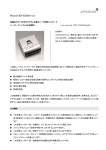
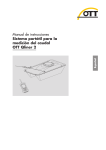
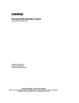
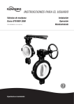
DOC026.97.80348
DOC026.97.80348
HL4 Sonde
11/2013, Edition 1
User Manual
ENGLISH ONLY
DOC026.97.80348
ENGLISH ONLY
DOC026.97.80348
Table of contents
Specifications on page 3
Maintenance on page 13
General information on page 3
Troubleshooting on page 17
Startup on page 6
Replacement parts and accessories on page 17
Operation on page 8
Specifications
Specifications are subject to change without notice.
Specification
Details
Dimensions
Diameter: 4.44 cm (1.75 in.) without rubber bumpers; 5.33 cm (2.1 in.) with rubber
bumpers
Length: 51.43 cm (20.25 in.) with no internal battery pack and standard sensor
guard; 66.358 cm (26.125 in.) with no internal battery pack and extended sensor
guard; 62.23 cm (24.5 in.) with internal battery pack and standard sensor guard;
77.787 cm (30.625 in.) with internal battery pack and extended sensor guard
Weight
2.2 kg (5 lb) with internal battery pack and storage/calibration cup
Power requirements
6–24 VDC (12 VDC nominal) applied to the communications module, 12 VDC:
250 mW average, 18 W peak
Internal battery pack
(optional)
Internal alkaline D-cell battery, non-rechargeable
Operating temperature1
–5 to 50 °C (23 to 122 °F), non-freezing
Storage temperature
1 to 50 °C (34 to 122 °F)
Depth
200 m (656 ft) maximum
Approximately 75 days of use with a 15-minute logging interval and a 30-second
warm-up time with temperature, conductivity, pH and LDO sensors installed.
Note: Some sensors cannot be used at 200 m (656 ft). Refer to the sensor documentation for the
sensor depth specifications.
Tensile strength
(maximum)
Mooring cap: 68 kg (150 lb); deployment cable: 227 kg (500 lb)
Sensors
Temperature sensor, four external sensor ports and optional internal depth sensor
Refer to the sensor documentation for sensor specifications.
Communications
Communications module: USB, SDI-12, RS232 Modbus, RS485 Modbus and
RS232 TTY
Logging
4 GB of internal memory2; 1 second interval minimum
1
2
Operation outside of this temperature range can result in mechanical damage or faulty electronic performance.
Sufficient memory to keep 5 years of continuous measurements with a 15-minute logging interval
General information
In no event will the manufacturer be liable for direct, indirect, special, incidental or consequential
damages resulting from any defect or omission in this manual. The manufacturer reserves the right to
make changes in this manual and the products it describes at any time, without notice or obligation.
Revised editions are found on the manufacturer’s website.
ENGLISH ONLY
English 3
DOC026.97.80348
Safety information
NOTICE
The manufacturer is not responsible for any damages due to misapplication or misuse of this product including,
without limitation, direct, incidental and consequential damages, and disclaims such damages to the full extent
permitted under applicable law. The user is solely responsible to identify critical application risks and install
appropriate mechanisms to protect processes during a possible equipment malfunction.
Please read this entire manual before unpacking, setting up or operating this equipment. Pay
attention to all danger and caution statements. Failure to do so could result in serious injury to the
operator or damage to the equipment.
Make sure that the protection provided by this equipment is not impaired. Do not use or install this
equipment in any manner other than that specified in this manual.
Use of hazard information
DANGER
Indicates a potentially or imminently hazardous situation which, if not avoided, will result in death or serious injury.
WARNING
Indicates a potentially or imminently hazardous situation which, if not avoided, could result in death or serious
injury.
CAUTION
Indicates a potentially hazardous situation that may result in minor or moderate injury.
NOTICE
Indicates a situation which, if not avoided, may cause damage to the instrument. Information that requires special
emphasis.
Precautionary labels
Read all labels and tags attached to the instrument. Personal injury or damage to the instrument
could occur if not observed. A symbol on the instrument is referenced in the manual with a
precautionary statement.
This symbol, if noted on the instrument, references the instruction manual for operation and/or safety
information.
Electrical equipment marked with this symbol may not be disposed of in European public disposal
systems after 12 August of 2005. In conformity with European local and national regulations (EU
Directive 2002/96/EC), European electrical equipment users must now return old or end-of-life
equipment to the Producer for disposal at no charge to the user.
Note: For return for recycling, please contact the equipment producer or supplier for instructions on how to return endof-life equipment, producer-supplied electrical accessories, and all auxiliary items for proper disposal.
Certification
Canadian Radio Interference-Causing Equipment Regulation, IECS-003, Class A:
Supporting test records reside with the manufacturer.
This Class A digital apparatus meets all requirements of the Canadian Interference-Causing
Equipment Regulations.
Cet appareil numérique de classe A répond à toutes les exigences de la réglementation canadienne
sur les équipements provoquant des interférences.
FCC Part 15, Class "A" Limits
Supporting test records reside with the manufacturer. The device complies with Part 15 of the FCC
Rules. Operation is subject to the following conditions:
4 English
ENGLISH ONLY
DOC026.97.80348
1. The equipment may not cause harmful interference.
2. The equipment must accept any interference received, including interference that may cause
undesired operation.
Changes or modifications to this equipment not expressly approved by the party responsible for
compliance could void the user's authority to operate the equipment. This equipment has been tested
and found to comply with the limits for a Class A digital device, pursuant to Part 15 of the FCC rules.
These limits are designed to provide reasonable protection against harmful interference when the
equipment is operated in a commercial environment. This equipment generates, uses and can
radiate radio frequency energy and, if not installed and used in accordance with the instruction
manual, may cause harmful interference to radio communications. Operation of this equipment in a
residential area is likely to cause harmful interference, in which case the user will be required to
correct the interference at their expense. The following techniques can be used to reduce
interference problems:
1. Disconnect the equipment from its power source to verify that it is or is not the source of the
interference.
2. If the equipment is connected to the same outlet as the device experiencing interference, connect
the equipment to a different outlet.
3. Move the equipment away from the device receiving the interference.
4. Reposition the receiving antenna for the device receiving the interference.
5. Try combinations of the above.
Product overview
NOTICE
Do not use this instrument in water that contains contamination that will cause damage to the sensors or the
housing (e.g., extreme acids or bases, high concentrations of organic solvents, oil/grease, toxic metals or
radioactive waters).
This portable instrument is used for spot measuring or unattended monitoring of environmental water
sources (fresh and salt water). Refer to Figure 1. The parameters measured by the instrument are
identified on the instrument and the Hydrolab Operating Software.
This instrument has a temperature sensor, four external sensor ports and an optional internal depth
sensor. The four external sensor ports can include a maximum of four different sensors. Refer to the
part numbers on the sensors and the sensor documentation to identify the sensors installed. All
sensors are installed at the factory and are not user-replaceable without authorization from the
manufacturer.
Figure 1 Instrument overview
1 Calibration cap for the storage/calibration cup
6 Middle rubber bumper (2x)3
2 Storage/Calibration cup1
7 Battery compartment4
3 Sensors in clear pH 4 buffer
8 End rubber bumper (2x)3
4 Locking screw
(2x)2
9 Connector
5 Housing
1
2
3
4
The standard version is shown.
For manufacturer use only
Remove the middle bumpers and end bumpers as necessary to use the instrument in a narrow space such as
a 5-cm (2-in.) well.
Units with an internal battery pack only
ENGLISH ONLY
English 5
DOC026.97.80348
Product components
Make sure that all components have been received. Refer to Figure 2. If any items are missing or
damaged, contact the manufacturer or a sales representative immediately.
Figure 2 Instrument components
1 AC power adapter
6 Silicone grease packet
2 Calibration cable1
7 Sensor maintenance kit(s)3
3 HL4 sonde
8 Hydrolab Operating Software CD
4 D-cell battery2
9 USB communications module
5 Mooring cap
10 Sensor guard with weight4
1
2
3
4
Not for use in water. Instrument damage will occur.
Supplied with units with an internal battery pack
Supplied with some sensors.
The standard version is shown.
Startup
Install the battery
WARNING
Explosion hazard. Incorrect battery installation can cause the release of explosive gases. Be sure that
the battery is of the approved chemical type and is inserted in the correct orientation.
For instruments with an internal battery pack, install the supplied D-cell battery. Refer to Figure 3.
6 English
ENGLISH ONLY
DOC026.97.80348
Figure 3 Install the battery
Install the software
Install the Hydrolab Operating Software on a PC.
Items to collect:
• PC with Windows XP SP3 or newer
• Hydrolab Operating Software CD
1. Put the CD in the PC. The installation program starts.
2. Complete the steps in the software prompts to install the software on the PC.
Connect to the PC
Connect the instrument to the PC.
Items to collect:
•
•
•
•
PC with Hydrolab Operating Software
Calibration cable or optional deployment cable
Communications module
Power adapter*
1. Connect the instrument to the PC. Refer to Figure 4.
To connect to a different power adapter or communications module than those shown, refer to the
documentation supplied with the power adapter or the communications module.
Note: An external power connection is optional for instruments with an internal battery pack. The battery is not
used when external power is used.
2. At initial installation and each time a different USB port on the PC is used:
a. Windows prompts that a new device is found and opens a wizard window. Select No, not this
time to search for software, then click Next.
b. Select Install the software automatically (Recommended), then click Next. No CD is
necessary.
Windows installs the software driver for the communications module.
*
Optional for instruments with an internal battery pack
ENGLISH ONLY
English 7
DOC026.97.80348
3. Start the Hydrolab Operating Software. The connected instrument shows in the Connect to
Device field.
Note: If step 2 is not done at initial installation, the instrument will not be shown in the Connect to Device field.
4. Select the instrument, then click Connect.
Figure 4 Connect the instrument to the PC
Operation
Configuration
Configure the software, instrument and sensor settings. Refer to Configuration in the online help.
Calibration
Calibrate the sensors before initial use, at regular intervals and after sensor maintenance or
modifications. Refer to Calibration in the online help.
Periodically, do a calibration check to make sure that measurements are still within tolerance range.
Refer to Calibration in the online help.
Prepare the sensors for calibration
Before calibration, always rinse the storage/calibration cup and clean the sensors to prevent
contamination of the calibration standards.
1.
2.
3.
4.
Rinse the storage/calibration cup with clean water.
Clean the sensors. Refer to the sensor documentation for instructions.
Rinse the sensors at least three times with deionized water. Refer to Figure 5.
Rinse the sensors at least two times with a calibration standard. Refer to Figure 5.
For the best results, discard the deionized water and calibration standard after each rinse.
8 English
ENGLISH ONLY
DOC026.97.80348
Figure 5 Rinse the sensors
Deployment guidelines
NOTICE
Always install the mooring cap or connect the deployment cable to the instrument before deployment to keep the
connector dry. Do not use the calibration cable for deployment because the connector will get wet.
NOTICE
Always install the sensor guard before deployment or sensor damage can occur.
• Do not apply more than 68 kg (150 lb) of additional weight to the instrument when the mooring cap
is used.
• Do not apply more than 113 kg (250 lb) of additional weight to the instrument when the
deployment cable is used.
• Do not hang weight from the sensor guard. Refer to Specifications on page 3 for the tensile
strength of the mooring cap and deployment cable.
Cable care
• Lubricate the sealing surface of the mooring cap and the optional deployment cable with silicone
grease on a cotton swab at regular intervals and as necessary.
• Keep all non-waterproof cables (all cables except the deployment cable) in a clean, dry and noncorrosive environment. If a cable gets dirty or wet, clean and/or air dry the cable before use.
• Do not put non-waterproof cables in a coil any tighter than 30.5 cm (12 in.) in diameter or cable
damage can occur.
• Do not put a knot in cables or use clips to mark a depth.
• Do not bend or pull the deployment cable over pulleys with less than 10 cm (4 in.) radius or 20 cm
(8 in.) in diameter.
• Use a powered or hand-cranked reel with electrical slip-rings to lower and raise the instrument if
the cables are very long. A lighter reel without slip-rings for shorter cables can be used.
Short-term (attended) deployment
NOTICE
Do not put the instrument where the deployment cable could be cut or damaged by boat propellers or other
moving objects.
ENGLISH ONLY
English 9
DOC026.97.80348
Deployment with a PC
Items to collect:
•
•
•
•
•
PC with Hydrolab Operating Software
Sensor guard
Deployment cable
USB communications module
Power adapter**
1. Connect the instrument to the PC. Refer to Connect to the PC on page 7. Make sure to use the
deployment cable and not the calibration cable.
2. Remove the storage/calibration cup and install the sensor guard. Keep the storage/calibration cup
for later use. Refer to Figure 6. Do not let the sensors become dry.
3. Lower the instrument into the water to be measured. For the best results, make sure that all of the
instrument is in the water.
4. Click Monitoring to view real-time measurements. Refer to Monitoring in the online help.
When measurements are complete, prepare the instrument for travel. Refer to Prepare for storage or
travel on page 16.
Figure 6 Install the sensor guard
Long-term (unattended) deployment
Deployment with a mooring cap
Only instruments with an internal battery pack can be deployed with a mooring cap.
Items to collect:
•
•
•
•
•
•
•
PC with Hydrolab Operating Software
Sensor guard
Mooring cap
Rope or wire line
Calibration cable
USB communications module
Power adapter***
1. In the office or the field, add a new log to the instrument.
Measurements are saved to the new log according to the selected measurement interval and
date range.
a. Connect the instrument to a PC. Refer to Connect to the PC on page 7.
**
***
Optional for instruments with an internal battery pack
Optional for instruments with an internal battery pack
10 English
ENGLISH ONLY
DOC026.97.80348
b. Click Logging, then add a new log. Refer to Logging in the online help.
c. Select File>Disconnect from Device to disconnect the instrument from the PC.
Note: As an alternative, click Devices, select the instrument, then click Disconnect.
d. Disconnect the calibration cable from the instrument.
2. Install the mooring cap on the instrument. Refer to Figure 7. Turn the bottom of the mooring cap
to install it.
Note: To remove the mooring cap, turn the bottom of the mooring cap. The top of the mooring cap will not turn
when the mooring cap is installed.
3. In the field, attach a rope or wire line to the mooring cap. Refer to Figure 7.
4. Remove the storage/calibration cup and install the sensor guard. Refer to Figure 6 on page 10.
Keep the storage/calibration cup for later use. Do not let the sensors become dry.
5. Lower the instrument into the water to be measured. For the best results, make sure that all of the
instrument is in the water.
6. Attach the instrument to a buoy, anchor or structure. Refer to Attach to a buoy, anchor or
structure on page 12.
When deployment is complete, prepare the instrument for travel. Refer to Prepare for storage or
travel on page 16.
Figure 7 Install the mooring cap
Deployment with a data acquisition system or controller
To remotely collect real-time measurements from the instrument, connect the instrument to a data
acquisition system (i.e., data logger or modem) or a controller with an applicable communications
module.
The instrument stays in low-power (sleep) mode until it receives a command from the external device
to switch on, complete a measurement and transmit the measured parameters back to the external
device. Refer to the online help for SDI-12 commands and TTY commands supported by the
instrument. Refer to the manufacturer's website for Modbus commands.
Configure the communications module
Items to collect:
• PC with Hydrolab Operating Software
• Communications module
1. In the office or the field, connect the applicable communications module to a USB port on the PC.
2. Start the Hydrolab Operating Software. The connected communications module shows in the
Connect to Device field.
3. Select the communications module, then click Connect. The configuration windows for the
communications module shows.
4. Configure the communications module. Refer to Configuration in the online help.
ENGLISH ONLY
English 11
DOC026.97.80348
5. When configuration is completed, disconnect the communications cable from the PC.
a. Select File>Disconnect from Device to disconnect the communications cable from the PC.
Note: As an alternative, click Devices, select the communications cable, then click Disconnect.
b. Disconnect the communications cable from the PC.
Connect the communications module
Items to collect:
• Data acquisition system or controller
• Communications module (configured)
• External power source, 6-24 VDC (12 VDC nominal) ****
1. In the field, connect the communications module to the data acquisition system or controller.
Refer to the documentation supplied with the communications module for wiring information.
Refer to Data transmission and power wiring on page 12 for the wiring requirements for data
transmission.
2. If the data acquisition system or controller cannot supply power to the communications module,
connect an external power source to the communications module. Refer to Data transmission and
power wiring on page 12 for the wiring requirements for external power.
Data transmission and power wiring
To connect data transmission lines to the communications module, make sure that the transmission
cable is sufficient for the operating current and will transfer the data without distortion. For up to
305 m (1000 ft) of cable, three 26 AWG wires are sufficient.
To connect external power to the communications module, make sure to use two 18 AWG wires for
power. Smaller power wires can be used if the power supply is near the instrument.
Instrument deployment
Items to collect:
• Deployment cable
• Sensor guard
1. Connect the deployment cable to the communications module. Make sure to use the deployment
cable and not the calibration cable.
2. Connect the deployment cable to the instrument.
3. Remove the storage/calibration cup and install the sensor guard. Keep the storage/calibration cup
for later use. Refer to Figure 6 on page 10. Do not let the sensors become dry.
4. Lower the instrument into the water to be measured. For the best results, make sure that all of the
instrument is in the water. Do not put the communications module in the water.
5. Attach the instrument and cabling to a structure. Refer to Attach to a buoy, anchor or structure
on page 12.
When deployment is complete, prepare the instrument for travel. Refer to Prepare for storage or
travel on page 16.
Attach to a buoy, anchor or structure
NOTICE
Do not use pipe clamps to attach the instrument because instrument damage can occur.
For unattended monitoring, attach the instrument to a buoy, anchor or structure.
****
Optional for instruments with an internal battery pack. Not used when the data acquisition
system or the controller can supply power to the communications module.
12 English
ENGLISH ONLY
DOC026.97.80348
Install in a location:
• Where instrument damage will not occur such as from floating material, sand, gravel, silt,
navigation or vandalism
• Where the instrument will not come in contact with mud such as after the water recedes
• Where ice will not form around the instrument or sensors
To attach the instrument to a:
• Buoy—use a marking buoy that will not attract vandalism.
• Structure—attach the instrument to the downstream side of a piling to prevent damage from
floating material. Refer to Figure 8. Carefully install straps such as web belts and large plastic Tiewraps on both ends of the instrument housing. Attach the deployment cable in the same way (if
used) to prevent cable damage from floating material, navigation and vandalism. To prevent
vandalism, install the instrument and cable so they are not easily seen.
Figure 8 Attach the instrument to a structure
Maintenance
CAUTION
Multiple hazards. Only qualified personnel must conduct the tasks described in this section of the
document.
CAUTION
Personal injury hazard. Because of pressure buildup inside of the instrument, removable parts can
disengage with force when removed. Loosen and remove the parts slowly. Point the parts away from
people and wear the appropriate protective equipment during maintenance or service activities.
NOTICE
Do not disassemble the instrument for maintenance without authorization from the manufacturer. If the internal
components must be cleaned or repaired, contact the manufacturer.
ENGLISH ONLY
English 13
DOC026.97.80348
NOTICE
Keep the instrument in a location where the sensors will not freeze or sensor damage will occur.
Clean the housing and the sensor guard
NOTICE
To prevent damage to some sensors and the instrument, do not use solvents that dissolve plastic to clean the
housing and sensor guard.
At regular intervals, examine the instrument housing and sensor guard. Clean the housing and
sensor guard as necessary to remove unwanted material and deposits.
1. Remove the sensor guard from the instrument.
2. Pour a minimum of 2.5 cm (1 in.) of pH 4 buffer or clean tap water into the storage/calibration
cup.
3. Install the storage/calibration cup on the instrument.
4. Clean the housing and sensor guard with:
• Mild detergent
• Non-toxic, degreasing solution, such as Simple Green® (A registered trademark of Sunshine
Makers, Inc.)
• Warm water
• Clean, soft toothbrush
• Soft cloth and/or cotton swabs
If necessary, soak the sensor guard and/or housing in water for at least 30 minutes to make the
contaminates soft and easier to remove.
5. Rinse the housing and sensor guard with clean water.
Clean the sensors
At regular intervals, examine the sensors for unwanted material, deposits (inorganic and biological)
and damage. Clean the sensors if unwanted material is found. In addition, clean the sensors if
sensor performance has degraded. Refer to the sensor documentation for cleaning instructions.
Replace any damaged parts (e.g., sensor membranes). Replace any parts with fouling (sedimentary
and/or biological) that affects performance and cannot be removed. Refer to the sensor
documentation for maintenance instructions.
Replace the battery
WARNING
Explosion hazard. Incorrect battery installation can cause the release of explosive gases. Be sure that
the battery is of the approved chemical type and is inserted in the correct orientation.
WARNING
Explosion hazard. An expired battery can cause hydrogen gas buildup inside the instrument. Replace
the battery before it expires. Do not store the instrument for long periods with a battery installed.
For instruments with an internal battery pack, replace the D-cell battery when the battery power level
is low. Refer to Figure 3 on page 7. The battery power level is shown at the top of the Hydrolab
Operating Software window.
Replace the battery with the same type and rating. Refer to the internal battery pack requirements in
Specifications on page 3.
14 English
ENGLISH ONLY
DOC026.97.80348
Keep the battery compartment dry when the battery is replaced. If water gets into the battery
compartment, remove the battery, pour the water out and fully dry the compartment with a towel. Let
the battery compartment air dry fully before use to prevent corrosion.
Note: The internal clock battery is not user-replaceable without authorization from the manufacturer.
Examine the O-rings and sealing gasket
1. At regular intervals, examine the O-rings and sealing gasket in the mooring cap for unwanted
material, wear or damage. Refer to Figure 9 and Figure 10.
2. Remove any unwanted material from the O-rings and mooring cap.
3. Replace any O-rings with visible damage or wear (e.g., cracks or missing pieces). Replace with
the O-rings from the manufacturer.
4. Apply silicone grease to the O-rings to prevent them from sticking and being pulled out of
position.
5. Replace the mooring cap when damage or wear is visible on the sealing gasket.
Figure 9 Sealing gasket location
1 Mooring cap sealing gasket
ENGLISH ONLY
English 15
DOC026.97.80348
Figure 10 O-ring locations
1 Battery compartment O-rings (4x)
3 Calibration cap O-ring
2 Storage/Calibration cup O-ring
Prepare for storage or travel
NOTICE
Keep the instrument in a location where the water in the storage/calibration cup will not freeze or sensor damage
will occur.
NOTICE
Do not keep the sensors in deionized water or sensor damage will occur.
NOTICE
Do not keep a turbidity sensor or flurometer in colored pH buffer or sensor damage will occur.
NOTICE
Do not keep the sensors in field sample water for long periods because biological growth can occur and
contaminate the sensors.
1. Rinse the instrument and sensors with clean tap water.
2. Remove the sensor guard and install the storage/calibration cup. Pour a minimum of 2.5 cm
(1 in.) of pH 4 buffer with no color or clean tap water into the storage/calibration cup. Refer to
Figure 11.
Note: It is not necessary for the sensors to be in the pH buffer or water.
Note: Do not keep a total dissolved gas sensor wet or the sensor membrane will be damaged.
3. Make sure that the end bumper is installed on the storage/calibration cup.
4. Install the mooring cap on the connector to keep the connector clean and dry.
16 English
ENGLISH ONLY
DOC026.97.80348
5. Put all non-waterproof cables (all cables except the deployment cable) in a dry container. Do not
put cables in a coil any tighter than 30.5 cm (12 in.) in diameter or cable damage can occur.
6. Before storage, clean the sensors. Refer to the sensor documentation.
7. For long-term storage, remove the internal D-cell battery if applicable. Refer to Figure 3
on page 7. No additional sensor preparation is necessary for long-term storage.
Figure 11 Prepare for storage or travel
Prepare for use after long-term storage
After the instrument has been in storage for more than 1 month,
1. Replace the electrolyte in the sensors, if applicable.
2. Calibrate the sensors. Refer to Calibration on page 8.
Rehydrate the sensors
If the sensors become dry, soak them in water for 8 hours before use.
Note: Do not keep a total dissolved gas sensor wet or the sensor membrane will be damaged.
Troubleshooting
Refer to Troubleshooting in the online help.
Replacement parts and accessories
WARNING
Personal injury hazard. Use of non-approved parts may cause personal injury, damage to the
instrument or equipment malfunction. The replacement parts in this section are approved by the
manufacturer.
Note: Product and Article numbers may vary for some selling regions. Contact the appropriate distributor or refer to
the company website for contact information.
ENGLISH ONLY
English 17
DOC026.97.80348
Replacement parts
Description
Item no.
Battery enclosure sleeve
9047300
Battery terminal cover
9032000
Bumper, rubber, end
9383100
Bumper, rubber, middle
9383200
Calibration cable
9310600
Cap, storage/calibration cup
9040900
Communications module, turck connector, dust cap
9046100
Communications module, USB
9162200
Communications module, USB, dust cap
9044400
Hydrolab Operating Software, CD
9282500
Maintenance kit, reference sensor
014660HY
Maintenance kit, LDO sensor
007460
Maintenance kit, pH integrated sensor
013410HY
Maintenance kit, turbidity sensor with wiper
9480800
Mooring cap
9310500
O-rings (4x), battery compartment
9048400
O-ring, storage/calibration cup and cap
002811
Power adapter, AC
002782
Power adapter, AC, dust cap
9044500
Sensor guard, standard
9383700
Sensor guard, standard with weight
9044100
Sensor guard, extended
9383800
Sensor guard, extended with weight
9044200
Sensor guard, weight
9041000
Shipping box, HL4 sonde
9309100
Storage/calibration cup, standard
003306
Storage/calibration cup, extended
003395HY
Silicone grease packet
000298HY
Accessories
Description
Item no.
Communications module, SDI-12
9039600
Communications module, RS485 Modbus
9039700
Communications module, RS232 Modbus
9039800
Communications module, RS232 TTY
9312900
Dust cap, 9-pin connector, for communications modules 9039800 and 9312900
9044600
18 English
ENGLISH ONLY
DOC026.97.80348
Accessories (continued)
Description
Item no.
Deployment cable, marine, 5 m
CZ005
Deployment cable, marine, 10 m
CZ010
Deployment cable, marine, 15 m
CZ015
Deployment cable, marine, 25 m
CZ025
Deployment cable, marine, 30 m
CZ030
Deployment cable, marine, 50 m
CZ050
Deployment cable, marine, 75 m
CZ075
Deployment cable, marine, 100 m
CZ100
Deployment cable, marine, 150 m
CZ150
Deployment cable, marine, 200 m
CZ200
Deployment cable, vented, 5 m
CV005
Deployment cable, vented, 10 m
CV010
ENGLISH ONLY
English 19
DOC026.97.80348
20 English
ENGLISH ONLY
DOC026.97.80348
ENGLISH ONLY
DOC026.97.80348
Hach Hydromet
5600 Lindbergh Drive
Loveland, CO 80538 U.S.A.
Tel. (970) 669-3050
(800) 949-3766 (U.S.A. only)
Fax (970) 461-3921
[email protected]
www.hachhydromet.com
OTT Hydromet
Ludwigstrasse 16
87437 Kempten, Germany
Tel. +49 (0)8 31 5617-0
Fax +49 (0)8 31 5617-209
[email protected]
www.ott.com
©
Hach Hydromet, 2013.
All rights reserved. Printed in U.S.A.
ENGLISH ONLY