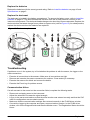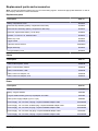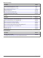
1
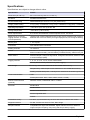
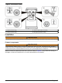
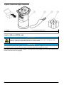
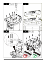
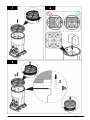
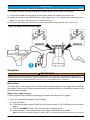
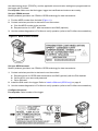
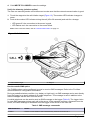
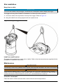
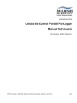
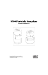
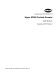
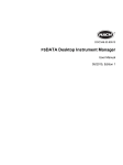
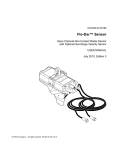
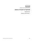
DOC026.97.80015
FL900 Series Flow Logger
07/2010, Edition 1
User Manual
Table of Contents
Specifications .............................................................................................................3
General Information .................................................................................................4
Safety information .......................................................................................................4
Use of hazard information ...........................................................................................4
Precautionary labels ...................................................................................................4
Confined space precautions .......................................................................................5
Product overview ........................................................................................................5
Installation ....................................................................................................................7
Product components ..................................................................................................7
Install a SIM card (GPRS only) ...................................................................................8
Install the batteries ....................................................................................................10
Attach an external power supply (optional) ............................................................... 12
Attach a sampler .......................................................................................................13
User interface ...........................................................................................................13
System startup .........................................................................................................14
Install the FL900 driver .............................................................................................14
Attach the logger to the computer .............................................................................14
Attach a sensor to the logger ....................................................................................14
Operation .....................................................................................................................15
Basic setup ...............................................................................................................15
Make a basic logger program ............................................................................15
Calibrate the sensor (Cal Wizard) ......................................................................16
Set up internet communication .................................................................................16
Set up a CDMA account ....................................................................................17
Set up a GPRS account .....................................................................................17
Configure the server ..........................................................................................17
Attach an antenna (wireless option) .................................................................. 18
Configure Flo-Ware for remote communication ................................................. 18
Verify the telemetry (wireless option) ................................................................. 19
Use the mobile SMS option ...............................................................................19
Site installation ........................................................................................................ 20
Hang from a cable .....................................................................................................20
Install on a wall bracket .............................................................................................20
Maintenance .............................................................................................................20
Clean the instrument .................................................................................................20
Replace the batteries ................................................................................................21
Replace the desiccant ...............................................................................................21
Troubleshooting .....................................................................................................21
Communication failure ..............................................................................................21
Replacement parts and accessories .............................................................. 22
1
Table of Contents
2
Specifications
Specifications are subject to change without notice.
Specification
Details
Dimensions (W x D x H)
25.4 x 22 x 40 cm (10.0 x 8.7 x 16.0 in.)
Enclosure
PC/ABS structural foam
Environmental rating
NEMA 6P/IP68 (24 hours at 1.8 m (6 ft) submersion)
Weight (model FL900)
4.5 kg (10 lb)—no batteries; 6.3 kg (14 lb)—2 batteries; 8.2 kg (18 lb)—4 batteries
Operating temperature
–18 to 60 ºC (0 to 140 ºF) at 95% RH
Storage temperature
–40 to 60 ºC (–40 to 140 ºF)
Power requirements
8 to 18 VDC from batteries or external power source, 2.5 W max
Battery life (at 15 minute
logging intervals, no modem,
room temperature)
185 days with 4 lantern batteries and a Flo-Dar sensor, 306 days with 4 lantern
batteries and a Flo-Tote sensor (for longer deployments, use a long-life battery)
Sensor ports
1, 2 or 4 ports
Connectors
IP67 stainless steel connectors
Datalog channels
16 maximum
Alarms
Maximum of 16 channel alarms with high/high, high, low, low/low options. System
alarms include low battery, low RTC battery, low slate memory, slate memory full.
Alarm actions
Start the sampler, change the log interval, change the call interval, send an e-mail
or a text message (SMS).
Logging intervals
1, 2, 3, 4, 5, 6, 10, 12, 15, 20, 30 or 60 minutes
Primary and secondary intervals for dynamic logging
Data storage
Event log: 1000 events maximum in non-volatile flash memory
Sample history: 2000 sample events maximum in non-volatile flash memory
Datalog: 325,000 data points; 1128 days for 3 channels at 15-minute log intervals
Local communication
USB
RS232 (Baud rates: 9600, 19200, 38400, 57600, 115200)
Remote communication
(optional)
Wireless modem; CDMA2000 1xRTT or GPRS
Protocols
Modbus RTU
Modbus ASCII
Mobile-Terminated SMS
Mobile-Originated SMS
TCP/IP
Timebase accuracy
±0.002%, synchronized every 24 hours with server software and modem
Supported sensors
Flo-Dar, Flo-Dar with SVS, Flo-Tote, Rain Gauge
Sampler interface
Compatible with Sigma 900 Standard, Sigma 900 Max and Hach SD900 to
support set point sampling, flow-pacing and sample history logging
English 3
Specification
Details
Certifications
Logger: CE; optional AC power supply: UL/CSA/CE Modems: FCC, NB, IC, others
may be available—contact the manufacturer for more information.
Warranty
1 year
General Information
In no event will the manufacturer be liable for direct, indirect, special, incidental or consequential
damages resulting from any defect or omission in this manual. The manufacturer reserves the right to
make changes in this manual and the products it describes at any time, without notice or obligation.
Revised editions are found on the manufacturer’s website.
Safety information
Please read this entire manual before unpacking, setting up or operating this equipment. Pay attention
to all danger and caution statements. Failure to do so could result in serious injury to the operator or
damage to the equipment.
Make sure that the protection provided by this equipment is not impaired, do not use or install this
equipment in any manner other than that specified in this manual.
Use of hazard information
DANGER
Indicates a potentially or imminently hazardous situation which, if not avoided, will result in death or serious injury.
WARNING
Indicates a potentially or imminently hazardous situation which, if not avoided, could result in death or serious injury.
CAUTION
Indicates a potentially hazardous situation that may result in minor or moderate injury.
NOTICE
Indicates a situation which, if not avoided, may cause damage to the instrument. Information that requires special
emphasis.
Precautionary labels
Read all labels and tags attached to the instrument. Personal injury or damage to the instrument could
occur if not observed. A symbol on the instrument is referenced in the manual with a precautionary
statement.
This is the safety alert symbol. Obey all safety messages that follow this symbol to avoid potential injury.
If on the instrument, refer to the instruction manual for operation or safety information.
This symbol, when noted on a product enclosure or barrier, indicates that a risk of electrical shock and/
or electrocution exists.
This symbol, if noted on the instrument or in the manual, indicates a risk of instrument damage due to
electrostatic discharge.
4 English
This symbol, if noted on the instrument, indicates that RF energy is emitted at or near this location.
Electrical equipment marked with this symbol may not be disposed of in European public disposal
systems after 12 August of 2005. In conformity with European local and national regulations (EU
Directive 2002/98/EC), European electrical equipment users must now return old or end-of-life
equipment to the Producer for disposal at no charge to the user.
Note: For return for recycling, please contact the equipment producer or supplier for instructions on how to return endof-life equipment, producer-supplied electrical accessories, and all auxillary items for proper disposal.
Confined space precautions
DANGER
Explosion hazard. Training in pre-entry testing, ventilation, entry procedures, evacuation/rescue
procedures and safety work practices is necessary before entering confined spaces.
The information that follows is supplied to help users understand the dangers and risks that are
associated with entry into confined spaces.
Definition of a confined space:
A confined space is any location or enclosure that has (or has the immediate potential for) one or more
of the following conditions:
• An atmosphere with an oxygen concentration that is less than 19.5% or more than 23.5% and/or a
hydrogen sulfide (H2S) concentration that is more than 10 ppm.
• An atmosphere that can be flammable or explosive due to gases, vapors, mists, dusts or fibers.
• Toxic materials which upon contact or inhalation can cause injury, impairment of health or death.
Confined spaces are not designed for human occupancy. Confined spaces have a restricted entry and
contain known or potential hazards. Examples of confined spaces include manholes, stacks, pipes,
vats, switch vaults and other similar locations.
Standard safety procedures must always be obeyed before entry into confined spaces and/or locations
where hazardous gases, vapors, mists, dusts or fibers can be present. Before entry into a confined
space, find and read all procedures that are related to confined space entry.
Product overview
The FL900 series flow loggers are used in open-channel flow monitoring studies such as inflow &
infiltration (I&I), combined sewer overflow (CSO), capacity and planning and storm water runoff
monitoring.
Data is collected from attached sensors and logged for future retrieval. The sensors can be added or
changed in the field. Depending on the model, up to four sensors can be connected. The data can be
retrieved directly through a USB or RS232 cable or remotely through a wireless network with Flo-Ware
desktop software and FSDATA server software. Refer to Figure 1. The FL900 Series loggers can also
connect to an external power source, rain gauge or be used to pace a Sigma sampler.
The wireless option and the number of available connectors varies with the model of the logger. Refer
to Figure 2 and Figure 3.
English 5
Figure 1 System overview with wireless option
Figure 2 Connectors—side 1
1 Sensor (all models)
3 Computer—USB or RS232 cable (all models)
2 Sensor (FL902, FL904 only)
4 Auxiliary—external power or sampler (all but FL900)
6 English
Figure 3 Connectors—side 2
1 Sensor (FL904 only)
3 Antenna option (all but FL900)
2 Sensor (FL904 only)
4 Rain gauge (all but FL900)
Installation
WARNING
Personal injury hazard. Only qualified personnel should conduct the tasks described in this section of the manual.
Product components
WARNING
Electromagnetic radiation hazard. To meet the requirements of the FCC Grant, CE Mark and other regulatory
bodies, do not use or install the device with an antenna that is not supplied by the manufacturer. Make sure that all
antennas are kept at a minimum distance of 20 cm (7.9 in.) from all personnel in normal use.
Make sure that all components have been received. Refer to Figure 4. If any items are missing or
damaged, contact the manufacturer or a sales representative immediately.
English 7
Figure 4 FL900 series logger components
1 Logger
3 D-ring with threaded lock
2 Cable, suspension
4 Batteries, 6 V alkaline (4x)
Install a SIM card (GPRS only)
NOTICE
Potential Instrument Damage. Delicate internal electronic components can be damaged by static
electricity, resulting in degraded performance or eventual failure.
NOTICE
The instrument enclosure can break if the cover screws are over-tightened. Tighten the cover screws by hand with
a maximum torque of 2.0 Nm (20 in./lb). Make sure that the gasket is lubricated with grease.
If the instrument contains a GPRS modem, a SIM card from the mobile carrier must be installed (refer
to the illustrated steps on page 9).
8 English
1
2
3
4
English 9
Install the batteries
WARNING
Potential explosion hazard. Use only alkaline batteries. Other types of batteries can cause safety hazards.
NOTICE
Do not over-tighten the cover. Tighten until the cover just touches the O-ring, then tighten one-quarter to one-half
turn maximum from O-ring contact. Refer to step 3 on page 11. Keep the O-ring lubricated with silicone grease.
The instrument can use two or four 6-V batteries for power. Use 2 batteries for short-term use or 4
batteries for long-term use (for battery life, refer to Specifications on page 3). When only 2 batteries
are used, put both batteries on the same side of the compartment (A-A or B-B). Refer to the illustrated
steps on page 11.
Changes in temperature and pressure can cause a vacuum in the battery compartment. If this occurs,
a tool can be used to remove the cover (Figure 5).
Figure 5 Battery cover removal
10 English
1
2
3
English 11
Attach an external power supply (optional)
WARNING
Potential explosion hazard. The instrument is not approved for use in hazardous locations.
The instrument can be powered by an external long-life battery, an SD900 power supply or other source
that can supply power in the specified range (refer to Specifications on page 3). If the logger has both
external power and internal batteries, the internal batteries are used as an auxiliary power supply. When
the external power falls below 7.75 V, the internal batteries supply power until the voltage from the
external source is above 7.75 V.
1. Install the external power source in a safe location near the logger. Be sure to obey all safety
precautions for the power supply.
2. Attach the cable from the power source to the AUX connector on the logger (Figure 6).
3. Apply power to the power source, if applicable.
Figure 6 External power options
1 2-conductor power cable (Figure 7)
3 SD900 power supply
2 Power adapter cable
4 Long-life battery
12 English
Figure 7 2-conductor power cable wiring
1 Power—#16 AWG red
2 Common—#16 AWG black
Attach a sampler
The logger can attach to a Sigma 900 Standard, Sigma 900 Max or Hach SD900 sampler for flowpaced and set point sampling. The sampler also supplies power to the logger and to attached sensors.
Connect the auxiliary cable to the AUX port on the logger and to the auxiliary port on the sampler. To
make a sampler program, refer to the documentation that is supplied with the sampler.
User interface
The indicators on the user interface show the status of the instrument and the modem. Refer to
Figure 8 and Table 1.
Figure 8 User interface
1 Instrument without modem
2 Instrument with modem
Table 1 LED status indicators
Indicator
LED color Description
Green
Flashes every 3 seconds during normal operation. Flashes every 15
seconds during sleep mode.
Red
Flashes when an attached sensor does not agree with the logger program,
an expected sensor is not found or the sensor operation has failed.
Green
Stays green during a call to the server.
Red
Flashes red if the call to the server failed.
English 13
System startup
Install the FL900 driver
Pre-requisite: Before the FL900 logger is attached to a computer, make sure that Flo-Ware is installed
on the computer.
The FL900 Series Driver must be installed on the PC to communicate with the logger.
1. Find the link for the FL900 Series Driver on the Flo-Ware CD or from the website
http://www.hachflow.com/p_soft_floware_down.html
2. Click on the link and run the application. The install wizard starts.
3. Follow the on-screen instructions to install the driver. Use the recommended settings.
Attach the logger to the computer
Pre-requisite: Make sure that the FL900 driver is installed on the computer.
Connect only one logger to the computer.
1. Attach the logger to the computer (Figure 9).
2. When a USB cable is attached for the first time, the Found New Hardware wizard opens. Run the
new hardware wizard to install the USB driver for the logger. When finished, the message “Your
new hardware is installed and ready to use” is shown.
Figure 9 Attach the logger to a computer
Attach a sensor to the logger
Pre-requisite: Make sure that the connection status is offline.
14 English
NOTICE
The IP67 rating of the sensor connector is applicable only when the cap is installed on unused connectors.
The number of sensors that can attach to the logger varies with the model of the logger.
1. If the sensor cable has connectors on both ends, attach the cable to the sensor first.
2. Attach the sensor to any SENSOR port on the logger (Figure 10). Tighten the connector by hand.
Note: For rain gauges, attach the sensor to the RAIN connector.
3. Align the desiccant hub vertically and make sure that the air port points down (Figure 10).
Figure 10 Attach a sensor to the logger
Operation
WARNING
Electromagnetic radiation hazard. To meet the requirements of the FCC Grant, CE Mark and other regulatory
bodies, do not use or install the device with an antenna that is not supplied by the manufacturer. Make sure that all
antennas are kept at a minimum distance of 20 cm (7.9 in.) from all personnel in normal use.
Basic setup
The information in this manual can be used to make a simple program for the logger and to calibrate
the sensors. Refer to the Flo-Ware documentation for advanced options. Complete the sections in the
order that they are shown.
Make a basic logger program
A basic program must be written to the logger to specify the channels to be logged.
1. Open a communication session with the logger:
a. Open Flo-Ware.
b. In the Options panel, select FL900 Series>Communications. The FL900 series driver window
opens.
c. Click the CONNECT button. The Communications window opens.
d. Select the port on the computer where the logger is attached and click OK.
Note: If the sensor mismatch message is shown, select "Create new program based on sensors connected."
English 15
e. Make sure that the connection status shows Direct Connect- Online.
2. Complete the information in the Site Information menu:
Option
Description
Site Identification
Enter a unique name for the site.
Time Zone
Select the correct time zone for the site.
3. Click on the Datalog Setup menu.
4. Select the channels to be logged in the Select Datalog Channels section:
a. Expand the tree for the Logger channel group. The Power Supply channel is always shown in
this group. If the logger contains a port for a rain gauge, the Rain channel is also shown. To
include a Logger channel in the datalog, select the check box next to the channel name.
b. Expand the tree for each Port[1 ](Sensor Name) channel group to view the available channels
for the sensor.
c. To include a Sensor channel in the datalog, select the check box next to the channel name. The
log channel count increases each time a channel is selected.
Note: For loggers with multiple sensor ports, the port number is added to the channel name. For example,
Velocity 3 is the velocity channel name for sensor port 3.
5. Click WRITE TO LOGGER to save the settings.
Calibrate the sensor (Cal Wizard)
Pre-requisite: The sensor must be installed in the process and must be online for calibration.
The sensor can be configured and calibrated with the calibration wizard.
1.
2.
3.
4.
Click on the Programming tab in the FL900 Series Driver window.
Click on Sensor Port[1] (sensor name).
Click on the CAL WIZARD button. The Calibration Wizard window opens.
Select the options on each screen. When the Calibration Complete screen is shown, click
FINISH.
5. Click WRITE TO LOGGER to save the settings.
Set up internet communication
NOTICE
Network and access point security is the sole responsibility of the customer using the wireless instrument. The
manufacturer will not be liable for any indirect, special, incidental or consequential damages caused by a breach
in network security.
When the logger has a modem, data can be sent from the logger to the internet for remote access. The
user must first open an account with a mobile (wireless) provider. The instrument is then registered to
16 English
the data-hosting server (FSDATA), and the applicable communication settings are programmed into
the logger with Flo-Ware.
Pre-requisite: Make sure that the logger, logger test certificate and antenna are nearby.
Set up a CDMA account
Mobile (wireless) providers use CDMA or GPRS technology for data transmission.
1. Find the MEID number from the label (Figure 11).
2. Contact a wireless provider to start service on the modem:
a. Give the MEID number to the provider.
b. Request service for 1xRTT data transmission and SMS (optional).
3. Use the modem diagnostics in Flo-Ware to verify operation (refer to the Flo-Ware documentation).
Figure 11 MEID number location
Set up a GPRS account
Mobile (wireless) providers use CDMA or GPRS technology for data transmission.
1. Contact a wireless provider to start service on the modem:
a. Request service for GPRS data transmission and SMS (optional) with the PIN disabled.
b. Get the APN, user name and password.
c. Get a SIM card.
2. Install the SIM card in the logger. Refer to Install a SIM card (GPRS only) on page 8.
3. Use the modem diagnostics in Flo-Ware to verify operation (refer to the Flo-Ware documentation).
Configure the server
Pre-requisite: Serial number of the logger
Figure 12 Serial number location
English 17
NOTICE
Be sure to enter the serial number and SVC correctly to prevent communication failure.
1. Go to the website http://fsdata.hach.com to access the FSDATA server.
2. Enter the user name and password:
3.
4.
5.
6.
• User name—the default user name is the 8-digit customer ID number
• Password—the default password is HachWebData
Go to Instruments>Instrument Manager.
Click ADD NEW. The Add Instrument window opens.
Enter the serial number (SN) of the logger.
Select the Instrument Type.
7. Select the Active check box and click OK. The instrument is shown in the Instrument Manager.
8. Find and record the Server Verification Code (SVC). This code lets the logger connect to the server.
Attach an antenna (wireless option)
WARNING
Electromagnetic radiation hazard. To meet the requirements of the FCC Grant, CE Mark and other regulatory
bodies, do not use or install the device with an antenna that is not supplied by the manufacturer. Make sure that all
antennas are kept at a minimum distance of 20 cm (7.9 in.) from all personnel in normal use.
An antenna can be attached to the instrument for wireless communication. Various antenna options
are available. Refer to Replacement parts and accessories on page 22. Attach an antenna directly
to the logger or attach an antenna cable to the ANTENNA connector.
Configure Flo-Ware for remote communication
Pre-requisites: The logger must be attached to the computer. An account with a network provider
must be set up, and the server must be configured.
The settings for remote communication must be entered into Flo-Ware and then written to the logger.
1. Open a communication session with the logger:
a. Open Flo-Ware.
b. In the Options panel, select FL900 Series>Communications. The FL900 series driver window
opens.
c. Click the CONNECT button. The Communications window opens.
d. Select the port on the computer where the logger is attached and click OK.
Note: If the sensor mismatch message is shown, select "Create new program based on sensors connected."
e. Make sure that the connection status shows Direct Connect- Online.
2. Click on the Communications menu. Complete the modem information:
Option
Description
CDMA2000 1xRTT No additional configuration is necessary.
GPRS
Select the network provider and the modem frequency. Enter the user name and
password, if applicable.
3. Complete the server information:
Option
Description
Primary Call Interval
The frequency that the logger calls the server, not to exceed the logging interval.
Secondary Call Interval
The frequency that the logger calls the server during an alarm condition.
Server Verification Code The account number that allows a connection to the server.
18 English
4. Click WRITE TO LOGGER to save the settings.
Verify the telemetry (wireless option)
The user can manually send a call to the server to make sure that the network communication is good.
1. Touch the magnet to the call initiation target (Figure 13). The modem LED indicator changes to
green.
2. Look at the modem LED indicator during the call (45 to 90 seconds) and wait for a change:
• LED goes off—the connection to the server is good.
• LED flashes red—the connection to the server failed.
Note: If the connection failed, refer to Communication failure on page 21.
Figure 13 Call the server
1 Call initiation target
2 Magnet
Use the mobile SMS option
The FL900 modem can be configured to send or receive SMS messages. Refer to the Flo-Ware
documentation for configuration information.
During a predefined alarm condition (e.g. battery or high level), an SMS message can be sent directly
from the logger to an email address or a mobile telephone. This message is sent in addition to the
alarm messages that are sent from the server.
A mobile telephone can be used to send an SMS message to the logger (Table 2). The logger looks
for new SMS messages during each call to the server. If the message requires a response from the
server, the SMS message is forwarded from the logger to the server on the next call.
Table 2 SMS message commands
SMS Command
Action
CURR?
Get the current status of the FL900 and any sensors connected to it
English 19
Site installation
Hang from a cable
NOTICE
Do not use the handles to hang the logger. The handles are not designed to hold the weight of the logger.
The logger can hang from a cable for installation in an area such as a manhole.
1. Connect a cable to the eye bolts on the top of the logger. Refer to Figure 14.
2. Hang the cable from a strong support such as a spanner bar.
Figure 14 Hang the logger from a cable
Install on a wall bracket
The logger can be attached to a wall, pole or ladder. Refer to the documents that are supplied with the
hardware for installation instructions.
Maintenance
WARNING
Personal injury hazard. Only qualified personnel should conduct the tasks described in this section of the manual.
WARNING
Electromagnetic radiation hazard. To meet the requirements of the FCC Grant, CE Mark and other regulatory
bodies, do not use or install the device with an antenna that is not supplied by the manufacturer. Make sure that all
antennas are kept at a minimum distance of 20 cm (7.9 in.) from all personnel in normal use.
Clean the instrument
Clean the exterior of the instrument with a moist cloth and a mild soap solution.
20 English
Replace the batteries
Replace the batteries with the same type and rating. Refer to Install the batteries on page 10 and
Specifications on page 3.
Replace the desiccant
The desiccant is located in the battery compartment. To remove the battery cover, refer to Install the
batteries on page 10. The desiccant absorbs moisture from the air and prevents corrosion to the
instrument components. The desiccant beads change color when they become saturated. Replace the
desiccant when the beads change from a yellow to a green color (refer to Figure 15). As a best practice,
replace the desiccant when the batteries are replaced.
Figure 15 Desiccant replacement
Troubleshooting
If problems occur in the system, try to find whether the problem is with the sensor, the logger or the
cable connections.
•
•
•
•
Examine all connections to the sensors. Make sure all connections are tight.
Remove and examine the sensor connectors for moisture. Clean and dry if necessary.
Examine the sensors for debris and remove the debris.
Examine the Event Log for problem events.
Communication failure
If a call was sent to the server but the connection failed, complete the following tasks:
• Disconnect and apply power to the instrument.
• Adjust the antenna to increase the signal strength.
• Log on to the server and make sure that the serial number was entered correctly and that the SVC
used for configuration was recorded correctly.
• Make sure that the communication settings were entered correctly in the FL900 driver window.
• Connect the logger to the computer and open a communications session. In the FL900 driver
window, click on the Diagnostics tab and then the Modem menu. The Registration Status should be
Home.
English 21
Replacement parts and accessories
Note: Product and Article numbers may vary for some selling regions. Contact the appropriate distributor or refer to
the company website for contact information.
Replacement parts
Description
Item no.
Battery compartment cover
8524400
Desiccant cap assembly (battery compartment desiccant)
8754900
Desiccant tube assembly (battery compartment desiccant)
8535200
Desiccant, replacement beads (1.5 can bulk)
8755500
Eyebolts, 1/4–20 x 2.5-in. stainless steel
8535500
Gasket, top cover
8533300
Logger handle
8524200
Lubricant, silicone 0.25 oz
000298HY
Magnet assembly
8537800
O-ring for battery cover
8533400
Cables
Description
Cable, external power, 2-wire
Item no.
8528700
Cable, communication, RS232
8528200
Cable, communication, USB
8528300
Cable, connect to sampler, 9 ft
8528400
Cable, connect to sampler, 25 ft
8528401
Power
Description
Item no.
Battery, 6 V lantern
11013M
Battery, long-life alkaline
8542900
Long-life alkaline battery pack top cap adapter and cable
8543000
Cable, power supply adapter (3 pin to 7 pin)
8528600
Power Supply, 110–120 VAC, US plug—requires 8528600 adapter cable
8754500US
Power Supply, 110–120 VAC, Australia plug—requires 8528600 adapter cable
8754500AU
Power Supply, 110–120 VAC, EU plug—requires 8528600 adapter cable
8754500EU
Power Supply, 110–120 VAC, Italy plug—requires 8528600 adapter cable
8754500IL
Power Supply, 110–120 VAC, UK plug—requires 8528600 adapter cable
8754500UK
22 English
Mounting hardware
Description
Item no.
Manhole Support Bracket/Spanner, 18–28 in.
9542
Manhole Support Bracket/Spanner, 28–48 in.
Manhole Support Bracket, 18–27 in.
9557
5713000
Suspension Cable, 16 in.
8544300
Wall-mount Bracket with ladder hanger
8544500
Wall-mount Bracket without ladder hanger
8542700
Antennas
Description
Item no.
Antenna, half-wave (824–894, 1850–1990 MHz)—US
5228400
Antenna, half-wave (870–960, 1710–1880 MHz)—EU
5255300
Antenna, traffic-rated in road (824–894 MHz)
6246200
Antenna, traffic-rated in road (1850–1990 MHz)
6683000
Antenna, traffic-rated manhole lid (824–896, 1850–1990 MHz)—US
5255400
Antenna, mini-wing (824–960, 1710–2170 MHz)—US
6241804
Extension cable, 15 ft
5244000
Extension cable, 70 ft
5249100
External devices
Description
Item no.
Rain Gauge with 100-ft cable
8542800
For samplers, refer to www.hach.com for part numbers and accessories
English 23
www.hachflow.com
© Hach Company, 2010. All rights reserved. Printed in the U.S.A.