1
ITALIAN TECHNOLOGY
grifo®
Please remark that to guarantee the integrity of data stored in FLASH EPROM and to assure
everytime the presence of program FLASH WRITER, this latter is always written in the last sector
of the component and it can be written only by grifo®. The user can obtain other FLASH EPROMs
for working or to install on a production system by ordering them to grifo® using the code FWR xxx
or FWR www.512K, as described in chapter "GCTR VERSIONS".
BOARD CONFIGURATION
To manage correctly FLASH WRITER, the user must perform the following hardware configurations:
1234-
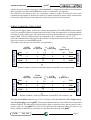
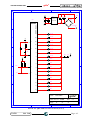
Connect the serial line A of the control card to the serial line of the development PC chosen
during installation using the communication cable described in figure 1.
Install the FLASH EPROM labelled “FWR xxx ...” on the specific socket of the control card.
Install at least 128KBytes of SRAM on the specific sockets of the control card.
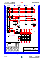
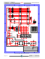
Configure the jumpers of the control card according to its hardware configuration and select
the DEBUG mode following the indications on the technical manual or figure 4 in this manual.
NOTE: For GPC® 188F and GPC® 188D do not connect jumpers J16 and J17.
FLASH EPROM AREAS
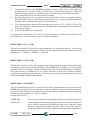
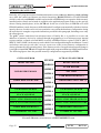
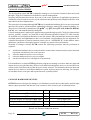
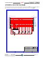
Referring to figures 5 and 6, only the areas marked with (*) can be modified through the program
FLASH WRITER. Here follows a short description of these areas.
1-
2-
3-
FLASH WRITER area: it corresponds to the last 16K Bytes of the FLASH and it contains the
code of the FLASH management program. The control card always executes this portion of
code after a reset or a power on, its first action is to detect whether RUN or DEBUG mode are
set and, in consequence, run the program stored in FLASH (RUN mode) or the FLASH
WRITER (DEBUG mode). This area cannot be modified by the user in any way in order to
avoid wrong situations which would prejudice the control card correct working.
Not used area: it may be present in FLASH EPROMs whose sector size is greater than the
16KBytes required by the FLASH WRITER area. Size of this area is variable (for example 0K
Bytes for 128Kx8 FLASH and 48KBytes for 512Kx8 FLASH), however it corresponds to an
area not usable for any operation.
User area: it corresponds the remaining free space on the FLASH except for the two previous
areas (for example 112K Bytes for 128Kx8 FLASH, 448K Bytes for 512Kx8 FLASH) and it
can contain code and/or data like the application program, configuration data, messages,
tables, etc. In RUM mode the control card always starts by executing the code stored at the
beginning of this area.
In the user area can be stored one or more binary files located on development PC mass memory
devices (floppy disk, hard disk, etc.) that have been generated by GCTR or other software
packages. These files can be written to FLASH EPROM starting from an user specified address
until the last file is writtern or the user area is full. User area cannot be written twice with
different data (in such case a FLASH EPROM malfunctioning error is visualized), so user area
must first be deleted.
GCTR
Rel. 5.40
Page 13