1
SAFETY PRECAUTIONS
(Read these precautions before use.)
Before using the product, read this manual and the associated manuals introduced in this manual carefully
and handle the product correctly with full attention to safety.
The precautions given in this manual are concerned with this product only. Refer to the user's manual of the
network system for safety precautions for the network system used.
The
SAFETY PRECAUTIONS
"CAUTION".
classify the safety precautions into two levels: "DANGER" and
DANGER
Indicates that incorrect handling may cause hazardous conditions,
resulting in death or severe injury.
CAUTION
Indicates that incorrect handling may cause hazardous conditions,
resulting in medium or slight personal injury or physical damage.
Depending on circumstances, operations indicated by
sure to observe the instructions of both levels.
CAUTION may also cause serious results. Be
Please store this manual in a safe place for future reference, and always forward it to the end user.
A-1
[DESIGN PRECAUTIONS]
DANGER
Create an interlock circuit on the program so that the system will operate safely based on the
communication status information. Failure to do so may cause an accident due to an erroneous
output or malfunction.
When an error occurs, all outputs are turned OFF in the MELSEC-ST system (at default).
However, I/O operations of the head module and respective slice modules can be selected for the
errors described below.
Select the status for each module for the entire system safety.
(1) Communication error (
Section 4.3.1 Output status setting for module error)
(2) Slice module error
The output status for the case of an error can be set to Clear, Hold or Preset with a command
parameter of each slice module. (For setting availability, refer to the manual for each slice
module.)
Since the parameter is defaulted to Clear, outputs will be turned off if an error occurs.
This parameter setting can be changed to Hold or Preset when the system safety is more
ensured by holding or presetting the output. (
of various functions")
Manual for each slice module, "Combinations
Create an external failsafe circuit so that the MELSEC-ST system will operate safely, even when the
external power supply or the system fails.
Failure to do so may cause an accident due to an erroneous output or malfunction.
(1) The status of output changes depending on the setting of various functions that control the
output. Take sufficient caution when setting for those functions.
(2) Outputs may be kept ON or OFF due to malfunctions of an output element or its internal circuit.
For signals which may cause a serious accident, configure an external monitoring circuit.
CAUTION
Initialize the network system after changing parameters of the MELSEC-ST system or the network
system. If unchanged data remain in the network system, this may cause malfunctions.
Do not install the control cables or communication cables together with the main circuit or power
cables.
Keep a distance of 100mm or more between them.
Failure to do so can result in malfunctions due to noise.
A-2
[INSTALLATION PRECAUTIONS]
CAUTION
Use the MELSEC-ST system in an environment that meets the general specifications described in
the MELSEC-ST System User's Manual.
Failure to do so may cause an electric shock, fire, malfunction, or damage to or deterioration of the
product.
Fix the head module and base module to the DIN rail one by one and secure them with end brackets.
Incorrect mounting may result in a fall of the module, short circuits or malfunctions.
Secure the module with several end brackets when using it in an environment of frequent vibrations.
Tighten the screws of the end brackets within the specified torque range.
If the screws are too loose, it may cause a fall of a module, short circuit, or malfunction.
Overtightening can also cause a fall due to damage to the screw or module, short circuit, or
malfunction.
Shut off all phases of the external power supply for the whole system before mounting or removing a
module.
Failure to do so may damage the module.
(1) Online replacement of the power distribution module and/or base module is not allowed.
Before replacing either of these modules, shut off all phases of the external power supply.
Failure to do so may result in damage to all devices of the MELSEC-ST system.
(2) I/O modules and intelligent function modules can be replaced online.
Since the online module replacement procedures vary depending on the module type, be sure to
replace it as instructed.
Refer to the user's manual of the head module for details on I/O modules, and refer to the
chapter of online module change in the user's manual of each intelligent function module for
details on the intelligent function module.
Do not directly touch the module's conductive parts or electronic components.
Doing so may cause malfunctions or failure of the module.
Connect each connection cable securely.
Failure to do so may cause malfunctions due to poor contact.
Use a conductive DIN rail and be sure to ground it.
Failure to do so may cause an electric shock or malfunctions.
If the screws are too loose, it may cause a short circuit or malfunction.
Overtightening can cause a short circuit due to screw damage.
A-3
[WIRING PRECAUTIONS]
DANGER
Before installation or wiring, shut off all phases of the external power supply used by the entire
system.
Failure to do so may cause an electric shock or damage to the product.
CAUTION
Ground the control panel, in which the MELSEC-ST system is installed, in the manner specified for
the MELSEC-ST system.
Failure to do so may cause an electric shock or malfunctions.
Check the rated voltage and terminal layout and wire the system correctly.
Connecting an inappropriate power supplt or incorrect wiring can result in a fire or failure.
Tighten the terminal screws within the specified torque range.
If the terminal screws are too loose, it may cause a short circuit or malfunction.
Overtightening can cause a short circuit due to damage to the screw or module, or malfunctions.
Prevent foreign matter such as dust or wiring chips from entering the module.
Failure to do so may cause a fire, failure, or malfunctions.
Place the communication cables or power cables connected to the module in a duct, or clamp them.
If not, dangling cables may swing or inadvertently be pulled, resulting in damage to the module or
cables or malfunctions due to poor cable contact.
When disconnecting the communication cable or power cable from the module, do not hold and pull
the cable part.
Pulling the cable connected to the module can damage the module and cable or can cause a
malfunction due to poor contact.
A-4
[STARTUP AND MAINTENANCE PRECAUTIONS]
DANGER
Do not touch the terminals or connectors while power is on.
Doing so may cause an electric shock or malfunctions.
Before cleaning or retightening the terminal screws, shut off all phases of the external power supply
used by the entire system.
Failure to do so may cause the module to fail or malfunction.
CAUTION
Do not disassemble or remodel the module.
Doing so may cause a failure, malfunctions, injuries, or a fire.
Do not drop or give a strong impact to the module since its case is made of resin.
Doing so may damage the module.
Before mounting the module to or removing it from the control panel, shut off all phases of the
external power supply used by the entire system.
Failure to do so may cause the module to fail or malfunction.
The number of terminal block installations/removals is limited to 50 times or less. (IEC 61131-2
compliant)
Exceeding the count of 50 may cause malfunctions.
Before handling the module, touch a grounded metal object to discharge the static electricity from
the human body.
Failure to do so may cause the module to fail or malfunction.
When using any radio communication device such as a cellular phone, keep a distance of at least
25cm (9.85inch) away from the MELSEC-ST system in all directions.
Failure to do so may cause malfunctions.
[DISPOSAL PRECAUTIONS]
CAUTION
When disposing of this product, treat it as industrial waste.
A-5
REVISIONS
* The manual number is given on the bottom left of the back cover.
Print Date
Apr., 2008
* Manual Number
Revision
SH(NA)-080754ENG-A First edition
Japanese Manual Version SH-080748-A
This manual confers no industrial property rights or any rights of any other kind, nor does it confer any patent licenses. Mitsubishi Electric
Corporation cannot be held responsible for any problems involving industrial property rights which may occur as a result of using the
contents noted in this manu.
2008 MITSUBISHI ELECTRIC CORPORATION
A-6
INTRODUCTION
Thank you for choosing the ST1H-BT MELSEC-ST CC-Link head module.
Before using the module, please read this manual carefully to fully understand the functions and
performance of the ST1H-BT MELSEC-ST CC-Link head module and use it correctly.
CONTENTS
SAFETY PRECAUTIONS•••••••••••••••••••••••••••••••••••••••••••••••••••••••••••••••••••••••••••••••••••••••••••••••••••••• A - 1
REVISIONS••••••••••••••••••••••••••••••••••••••••••••••••••••••••••••••••••••••••••••••••••••••••••••••••••••••••••••••••••••••• A - 6
INTRODUCTION •••••••••••••••••••••••••••••••••••••••••••••••••••••••••••••••••••••••••••••••••••••••••••••••••••••••••••••••• A - 7
CONTENTS••••••••••••••••••••••••••••••••••••••••••••••••••••••••••••••••••••••••••••••••••••••••••••••••••••••••••••••••••••••• A - 7
About Manuals •••••••••••••••••••••••••••••••••••••••••••••••••••••••••••••••••••••••••••••••••••••••••••••••••••••••••••••••••• A - 10
Compliance with the EMC and Low Voltage Directives ••••••••••••••••••••••••••••••••••••••••••••••••••••••••••••••••• A - 10
How to Read Manual••••••••••••••••••••••••••••••••••••••••••••••••••••••••••••••••••••••••••••••••••••••••••••••••••••••••••• A - 11
Generic Terms and Abbreviations••••••••••••••••••••••••••••••••••••••••••••••••••••••••••••••••••••••••••••••••••••••••••• A - 13
Term definition •••••••••••••••••••••••••••••••••••••••••••••••••••••••••••••••••••••••••••••••••••••••••••••••••••••••••••••••••• A - 14
Packing List •••••••••••••••••••••••••••••••••••••••••••••••••••••••••••••••••••••••••••••••••••••••••••••••••••••••••••••••••••••• A - 15
CHAPTER1 OVERVIEW
1.1
Features ••••••••••••••••••••••••••••••••••••••••••••••••••••••••••••••••••••••••••••••••••••••••••••••••••••••••••••••1 - 2
CHAPTER2 SYSTEM CONFIGURATION
2.1
1 - 1 to 1 - 5
2 - 1 to 2 - 2
Applicable Systems•••••••••••••••••••••••••••••••••••••••••••••••••••••••••••••••••••••••••••••••••••••••••••••••••2 - 2
CHAPTER3 SPECIFICATIONS
3 - 1 to 3 - 20
3.1
Performance Specifications••••••••••••••••••••••••••••••••••••••••••••••••••••••••••••••••••••••••••••••••••••••• 3 - 1
3.2
CC-Link Dedicated Cable Specifications •••••••••••••••••••••••••••••••••••••••••••••••••••••••••••••••••••••••3 - 2
3.3
Communication between Master Station and MELSEC-ST System ••••••••••••••••••••••••••••••••••••••3 - 3
3.4
Remote I/O, Remote Registers ••••••••••••••••••••••••••••••••••••••••••••••••••••••••••••••••••••••••••••••••••3 - 5
3.4.1
3.4.2
3.4.3
3.4.4
3.5
List of remote I/O signals ••••••••••••••••••••••••••••••••••••••••••••••••••••••••••••••••••••••••••••••••••••3 - 5
Remote I/O details ••••••••••••••••••••••••••••••••••••••••••••••••••••••••••••••••••••••••••••••••••••••••••••3 - 7
Remote register list ••••••••••••••••••••••••••••••••••••••••••••••••••••••••••••••••••••••••••••••••••••••••• 3 - 11
Remote register details •••••••••••••••••••••••••••••••••••••••••••••••••••••••••••••••••••••••••••••••••••• 3 - 13
Head Module Processing Time •••••••••••••••••••••••••••••••••••••••••••••••••••••••••••••••••••••••••••••••• 3 - 15
3.5.1
3.5.2
3.5.3
ST bus cycle time ••••••••••••••••••••••••••••••••••••••••••••••••••••••••••••••••••••••••••••••••••••••••••• 3 - 16
Input transmission delay time ••••••••••••••••••••••••••••••••••••••••••••••••••••••••••••••••••••••••••••• 3 - 19
Output transmission delay time••••••••••••••••••••••••••••••••••••••••••••••••••••••••••••••••••••••••••• 3 - 20
CHAPTER4 FUNCTIONS
4 - 1 to 4 - 33
4.1
Function List •••••••••••••••••••••••••••••••••••••••••••••••••••••••••••••••••••••••••••••••••••••••••••••••••••••••••4 - 1
4.2
CC-Link Functions ••••••••••••••••••••••••••••••••••••••••••••••••••••••••••••••••••••••••••••••••••••••••••••••••••4 - 3
A-7
4.2.1
4.2.2
4.2.3
4.3
RAS Functions••••••••••••••••••••••••••••••••••••••••••••••••••••••••••••••••••••••••••••••••••••••••••••••••••••• 4 - 12
4.3.1
4.4
Cyclic transmission function•••••••••••••••••••••••••••••••••••••••••••••••••••••••••••••••••••••••••••••••••4 - 3
Auto-optimization of no. of occupied stations and extended cyclic setting•••••••••••••••••••••••••4 - 7
Consistency function•••••••••••••••••••••••••••••••••••••••••••••••••••••••••••••••••••••••••••••••••••••••• 4 - 10
Output status setting for module error••••••••••••••••••••••••••••••••••••••••••••••••••••••••••••••••••• 4 - 12
Monitoring Function •••••••••••••••••••••••••••••••••••••••••••••••••••••••••••••••••••••••••••••••••••••••••••••• 4 - 15
4.4.1
Status monitoring function ••••••••••••••••••••••••••••••••••••••••••••••••••••••••••••••••••••••••••••••••• 4 - 15
4.5
Reading/Writing Intelligent Function Module Parameters••••••••••••••••••••••••••••••••••••••••••••••••• 4 - 17
4.6
Online Module Change Function••••••••••••••••••••••••••••••••••••••••••••••••••••••••••••••••••••••••••••••• 4 - 18
4.6.1
4.6.2
4.6.3
4.6.4
Precautions for online module change •••••••••••••••••••••••••••••••••••••••••••••••••••••••••••••••••• 4 - 18
Online module change procedure•••••••••••••••••••••••••••••••••••••••••••••••••••••••••••••••••••••••• 4 - 20
Online module change using the buttons on the head module••••••••••••••••••••••••••••••••••••• 4 - 21
Online module change from GX Configurator-ST ••••••••••••••••••••••••••••••••••••••••••••••••••••• 4 - 26
CHAPTER5 PREPARATION AND SETUP
5.1
Implementation and Installation ••••••••••••••••••••••••••••••••••••••••••••••••••••••••••••••••••••••••••••••••••5 - 1
5.1.1
5.2
Handling precautions •••••••••••••••••••••••••••••••••••••••••••••••••••••••••••••••••••••••••••••••••••••••••5 - 1
Preparation and Setup •••••••••••••••••••••••••••••••••••••••••••••••••••••••••••••••••••••••••••••••••••••••••••••5 - 2
5.2.1
5.2.2
5.3
5 - 1 to 5 - 20
Checking the MELSEC-ST system ••••••••••••••••••••••••••••••••••••••••••••••••••••••••••••••••••••••••5 - 2
Pre-operation procedures••••••••••••••••••••••••••••••••••••••••••••••••••••••••••••••••••••••••••••••••••••5 - 3
Part Names and Settings ••••••••••••••••••••••••••••••••••••••••••••••••••••••••••••••••••••••••••••••••••••••••••5 - 5
5.3.1
5.3.2
5.3.3
Mode switch ••••••••••••••••••••••••••••••••••••••••••••••••••••••••••••••••••••••••••••••••••••••••••••••••••••5 - 9
Station No. switches •••••••••••••••••••••••••••••••••••••••••••••••••••••••••••••••••••••••••••••••••••••••• 5 - 11
Resetting •••••••••••••••••••••••••••••••••••••••••••••••••••••••••••••••••••••••••••••••••••••••••••••••••••••• 5 - 14
5.4
Self-Diagnostics ••••••••••••••••••••••••••••••••••••••••••••••••••••••••••••••••••••••••••••••••••••••••••••••••••• 5 - 15
5.5
Wiring ••••••••••••••••••••••••••••••••••••••••••••••••••••••••••••••••••••••••••••••••••••••••••••••••••••••••••••••• 5 - 17
5.5.1
5.5.2
CC-Link dedicated cable wiring••••••••••••••••••••••••••••••••••••••••••••••••••••••••••••••••••••••••••• 5 - 17
Wiring precautions •••••••••••••••••••••••••••••••••••••••••••••••••••••••••••••••••••••••••••••••••••••••••• 5 - 20
CHAPTER6 PARAMETER SETTING
6.1
6 - 1 to 6 - 4
Parameters for Using MELSEC-ST System •••••••••••••••••••••••••••••••••••••••••••••••••••••••••••••••••••6 - 1
6.1.1
6.1.2
Network parameters ••••••••••••••••••••••••••••••••••••••••••••••••••••••••••••••••••••••••••••••••••••••••••6 - 1
Command parameters •••••••••••••••••••••••••••••••••••••••••••••••••••••••••••••••••••••••••••••••••••••••6 - 3
CHAPTER7 PROGRAMMING
7 - 1 to 7 - 25
7.1
System Configuration Example ••••••••••••••••••••••••••••••••••••••••••••••••••••••••••••••••••••••••••••••••••7 - 1
7.2
Settings and Communication Data ••••••••••••••••••••••••••••••••••••••••••••••••••••••••••••••••••••••••••••••7 - 3
7.3
Program Examples •••••••••••••••••••••••••••••••••••••••••••••••••••••••••••••••••••••••••••••••••••••••••••••••••7 - 9
CHAPTER8 COMMANDS
8 - 1 to 8 - 40
8.1
Command Execution Method and Procedures••••••••••••••••••••••••••••••••••••••••••••••••••••••••••••••••8 - 1
8.2
Commands •••••••••••••••••••••••••••••••••••••••••••••••••••••••••••••••••••••••••••••••••••••••••••••••••••••••••••8 - 7
8.2.1
A-8
Operating status read request (Command No.: 8100H/0100H)•••••••••••••••••••••••••••••••••••• 8 - 10
8.2.2
8.2.3
8.2.4
8.2.5
8.2.6
8.2.7
8.2.8
Error code read request (Command No.: 8101H/0101H) ••••••••••••••••••••••••••••••••••••••••••• 8 - 15
Error history read request (Command No.: 8102H/0102H) ••••••••••••••••••••••••••••••••••••••••• 8 - 20
Error module information read request (Command No.: 0103H) •••••••••••••••••••••••••••••••••• 8 - 22
Error clear request (Command No.: 8104H/0104H) •••••••••••••••••••••••••••••••••••••••••••••••••• 8 - 25
Module mounting status read request (Command No.: 8105H/0105H) •••••••••••••••••••••••••• 8 - 27
Initial data batch write request (Command No.: 8106H) ••••••••••••••••••••••••••••••••••••••••••••• 8 - 30
Initial data individual write request (Command No.: 8107H/0107H)••••••••••••••••••••••••••••••• 8 - 33
8.3
Command Program Example••••••••••••••••••••••••••••••••••••••••••••••••••••••••••••••••••••••••••••••••••• 8 - 37
8.4
Values Stored into Command Execution Result •••••••••••••••••••••••••••••••••••••••••••••••••••••••••••• 8 - 39
CHAPTER9 TROUBLESHOOTING
9 - 1 to 9 - 18
9.1
Before Troubleshooting ••••••••••••••••••••••••••••••••••••••••••••••••••••••••••••••••••••••••••••••••••••••••••••9 - 1
9.2
Troubleshooting Procedures••••••••••••••••••••••••••••••••••••••••••••••••••••••••••••••••••••••••••••••••••••••9 - 2
9.3
Troubleshooting on the Master Module•••••••••••••••••••••••••••••••••••••••••••••••••••••••••••••••••••••••••9 - 4
9.3.1
9.4
Troubleshooting on the Head Module•••••••••••••••••••••••••••••••••••••••••••••••••••••••••••••••••••••••••••9 - 6
9.4.1
9.4.2
9.4.3
9.4.4
9.5
When the ERR. LED is on or flashing •••••••••••••••••••••••••••••••••••••••••••••••••••••••••••••••••••••9 - 4
When the RUN LED is off •••••••••••••••••••••••••••••••••••••••••••••••••••••••••••••••••••••••••••••••••••9 - 6
When the L ERR. LED is on or flashing ••••••••••••••••••••••••••••••••••••••••••••••••••••••••••••••••••9 - 7
When the L RUN LED is off ••••••••••••••••••••••••••••••••••••••••••••••••••••••••••••••••••••••••••••••••• 9 - 9
When the ERR. LED is on or flashing ••••••••••••••••••••••••••••••••••••••••••••••••••••••••••••••••••• 9 - 10
When Cyclic Transmission is not Available •••••••••••••••••••••••••••••••••••••••••••••••••••••••••••••••••• 9 - 12
9.5.1
When I/O data are erroneous ••••••••••••••••••••••••••••••••••••••••••••••••••••••••••••••••••••••••••••• 9 - 13
9.6
When Commands cannot be Executed••••••••••••••••••••••••••••••••••••••••••••••••••••••••••••••••••••••• 9 - 14
9.7
Error Codes •••••••••••••••••••••••••••••••••••••••••••••••••••••••••••••••••••••••••••••••••••••••••••••••••••••••• 9 - 15
9.7.1
9.7.2
Reading error codes •••••••••••••••••••••••••••••••••••••••••••••••••••••••••••••••••••••••••••••••••••••••• 9 - 15
Error code list •••••••••••••••••••••••••••••••••••••••••••••••••••••••••••••••••••••••••••••••••••••••••••••••• 9 - 16
APPENDICES
App - 1 to App - 9
Appendix 1
External Dimensions •••••••••••••••••••••••••••••••••••••••••••••••••••••••••••••••••••••••••••••••••• App - 1
Appendix 2
Recommended Screwdriver ••••••••••••••••••••••••••••••••••••••••••••••••••••••••••••••••••••••••• App - 3
Appendix 3
MELSEC-ST System Setting Sheet •••••••••••••••••••••••••••••••••••••••••••••••••••••••••••••••• App - 4
Appendix 3.1
Appendix 3.2
Appendix 3.3
INDEX
I/O points sheet •••••••••••••••••••••••••••••••••••••••••••••••••••••••••••••••••••••••••••••••••• App - 4
Input data assignment sheet •••••••••••••••••••••••••••••••••••••••••••••••••••••••••••••••••• App - 5
Output data assignment sheet •••••••••••••••••••••••••••••••••••••••••••••••••••••••••••••••• App - 7
Index - 1 to Index - 3
A-9
About Manuals
The following manuals are related to this product.
Please place an order if necessary.
Relevant Manuals
Manual Name
Manual Number (Model Code)
MELSEC-ST System User's Manual
Describes the system configurations of the MELSEC-ST system, performance specifications,
functions, handling, wiring, and troubleshooting of power distribution modules, base modules, and
I/O modules.
SH-080456ENG
(13JR72)
(Sold separately)
GX Configurator-ST Version 1 Operating Manual
Describes how to operate GX Configurator-ST, how to set the intelligent function parameters, and
SH-080439ENG
(13JU47)
how to monitor the MELSEC-ST system.
(Sold separately)
CC-Link System Master/Local Module User's Manual
Describes the system configurations, performance specifications, functions, handling, wiring, and
SH-080394E
(13JR64)
troubleshooting of the QJ61BT11N.
(Sold separately)
Compliance with the EMC and Low Voltage Directives
(1) For MELSEC-ST system
To configure a system meeting the requirements of the EMC and Low Voltage
Directives when incorporating the Mitsubishi MELSEC-ST System (EMC and
Low Voltage Directives compliant) into other machinery or equipment, refer to Chapter
11 "EMC and Low Voltage Directive" in the MELSEC-ST System User's Manual.
The CE mark, indicating compliance with the EMC and Low Voltage Directives, is
printed on the rating plate of the MELSEC-ST system.
(2) For the product
For the compliance of this product with the EMC and Low Voltage Directives, refer to
Chapter 11 "EMC and Low Voltage Directives" in the MELSEC-ST System User's
Manual.
A - 10
How to Read Manual
In this manual, remote I/O, remote registers, and message transmission areas for CC-Link
are represented with Br , Wr , Cr , Bw , Ww , and Cw .
Master station
Remote device station (MELSEC-ST system)
Head module
Terminating resistor
Terminating resistor
CC-Link
Programmable
controller CPU
Master module
Head module
Slice
module
Remote input (RX)
Remote input
(RX)
Br Bit input area
Input
status
Remote register (RWr)
Wr Word input area
Remote register
(RWr)
Message transmission
Slice
module
Remote output
(RY)
Remote output (RY)
Remote register
(RWw)
Remote register (RWw)
Bw Bit output area
Output
status
Device
Command
Cw execution area
Ww Word output area
Command execution
G.RDMSG
Device
Command
Cr result area
Command result
(1) Data symbol
<Example of Cr Command result area>
Cr.0 (7-0)
Range
When the unit of data is one word (16 bits),
the corresponding bits are indicated.
(0) : Bit 0
(7-0): Range of bit 0 to bit 7
Detail data No.
Abbreviated data symbol
(2) in this section, (3) in this section
A - 11
(2) Head module
Master station
(a) Remote input (RX)
Data symbol
Br
Br.00
Area name
to
Br.n
Bit input area
Unit
Detail data No. notation
1 bit/symbol
Hexadecimal
Unit
Detail data No. notation
1 word/symbol
Hexadecimal
Unit
Detail data No. notation
1 word/symbol
Decimal
(b) Remote register (RWr)
Data symbol
Wr
Wr.00
Area name
to
Wr.n
Word input area
(c) Message transmission
Data symbol
Cr
Cr.0
Area name
to
Cr.n
(3) Master station
Command result area
Head module
(a) Remote output (RY)
Data symbol
Bw
Bw.00
Area name
to
Bw.n
Bit output area
Unit
Detail data No. notation
1 bit/symbol
Hexadecimal
(b) Remote register (RWw)
Data symbol
Ww
Area name
Ww.00 to
Ww.n
Unit
Detail data No. notation
1 word/symbol
Hexadecimal
Area name
Unit
Detail data No. notation
Command execution area
1 word/symbol
Decimal
Word output area
(c) Message transmission
Data symbol
Cw
A - 12
Cw.0
to
Cw.n
Generic Terms and Abbreviations
Unless otherwise specified, this manual uses the following generic terms and
abbreviations to explain the head module.
Generic term/
Description
Abbreviation
Head module
Bus refreshing module
Power feeding module
Power distribution module
Base module
Input module
Output module
Abbreviation for the ST1H-BT MELSEC-ST CC-Link head module.
Module that distributes external system power and auxiliary power to the head module and slice
modules.
Module that distributes external auxiliary power to slice modules.
Generic term for the bus refreshing module and power feeding module.
Generic term for a module that transfers data between the head module and slice module, and
between the slice module and external devices (including wiring).
Generic term for modules that handle input data in units of bits.
Generic term for modules that handle output data in units of bits.
Intelligent function module Generic term for modules that handle input/output data in units of words.
I/O module
Generic term for input modules and output modules.
Slice module
MELSEC-ST system
GX Configurator-ST
Generic term for power distribution modules, I/O modules, and intelligent function modules that
can be mounted on a base module.
Generic term for a system that is composed of a head module, slice modules, an end plate and
end brackets.
Configuration software dedicated to the MELSEC-ST system.
CC-Link
The general name of SWnD5C-STPB-E type products. (n=1 or later)
Abbreviation for Control & Communication Link system.
Master module
RDMSG
Abbreviation for the QJ61BT11N used as a master station.
Generic term for G.RDMSG and GP.RDMSG.
A - 13
Term definition
The following explains the meanings and definitions of the terms used in this manual.
Term
Cyclic transmission
Message transmission
Master station
Local station
Remote I/O station
Remote device station
Remote station
SB
Description
A communication method by which remote I/O data and remote register data are transferred
periodically.
A transmission method for writing parameters from the master station to a remote device
station and reading the remote device station status.
This station controls the entire data link system.
One master station is required for one system.
A station that has a programmable controller CPU and can communicate with the master
station and other local stations.
A remote station that can only use bit data. (Input from or output to external devices)
(AJ65BTB1-16D, AJ65SBTB1-16D, etc.)
A remote station that can use both bit and word data. (Input from or output to external devices,
analog data conversion)
(ST1H-BT, AJ65BT-64AD, AJ65BT-64DAV, AJ65BT-64DAI, etc.)
Generic term for remote I/O stations and remote device stations.
Controlled by the master station.
Link special relay (for CC-Link).
Bit data that indicate the module operating status and data link status of the master/local
station.
Link special register (for CC-Link).
SW
Data in units of 16 bits, which indicate the module operating status and data link status of the
master/local station.
Remote input (for CC-Link).
RX
Bit data that are input from remote stations to the master station.
Remote output (for CC-Link).
RY
Bit data that are output from the master station to remote stations.
Remote register (Read area for CC-Link).
RWr
Data in units of 16 bits, which are input from remote device stations to the master station.
Remote register (Write area for CC-Link).
RWw
Data in units of 16 bits, which are output from the master station to remote device stations.
Remote net Ver.1 mode
Remote net Ver.2 mode
I/O data
Br.n
Select this mode when extended cyclic setting is not needed or when the QJ61BT11 is replaced
with the QJ61BT11N.
Select this mode when creating a new system with extended cyclic setting.
Data transferred between the head module and the master station.
Generic term for RX, RY, RWr, and RWw.
Bit input area
Bit input data of each module.
Input data are sent from the head module to the master station through remote input (RX).
Bit output data of each module.
Bw.n
Bit output area
Output data are received from the master station to the head module through remote output
(RY).
Wr.n
Word input area
Word (16-bit) input data of an intelligent function module.
Input data are sent from the head module to the master station through remote register (RWr).
Word (16-bit) output data of an intelligent function module.
Ww.n Word output area
Output data are received from the master station to the head module through remote register
(RWw).
A - 14
Term
Cr.n
Command result
area
Cw.n
Command
execution area
Description
Information that indicates a command result.
This information is stored in Setting data (area starting from (D1)+1) of the dedicated instruction
(RDMSG) of the master station.
Information for executing a command.
This information is stored in Setting data (area starting from (S2)+1) of the dedicated instruction
(RDMSG) of the master station.
Number of occupied I/O
The area, which is equivalent to the occupied I/O points, is occupied in Br Bit input area/ Bw
points
Bit output area.
The number assigned to every 2 occupied I/O points of each module.
Slice No.
The numbers are assigned in ascending order, starting from "0" of the head module. (The
maximum value is 127.)
This is used for specifying a command execution target.
The number that shows where the slice module is physically installed.
Slice position No.
Start slice No.
Command
Command parameter
ST bus cycle time
The numbers are assigned in ascending order, starting from "0" of the head module. (The
maximum value is 63.)
This is used for specifying a command execution target.
The start slice No. assigned to the head module and slice modules.
Generic term for requests that are executed by the master station for reading each module's
operation status, setting intelligent function module command parameters or various controls.
Generic term for parameters set in commands or GX Configurator-ST.
All of the parameters set for the head module and slice modules are command parameters.
Processing time for the head module to refresh the input or output status of each slice module.
Abbreviation for Reliability, Availability, and Serviceability.
RAS
This term is used to express the overall usability of automation systems.
Packing List
The following is a packing list of the head module.
Model name
ST1H-BT
ST1A-EPL
ST1A-EBR
Product
Quantity
ST1H-BT MELSEC-ST CC-Link head module
ST1A-EPL end plate
1
1
ST1A-EBR end bracket
2
Terminating resistor 110 , 1/2W (brown, brown, brown)
Terminating resistor
(Used for wiring of CC-Link dedicated cables or Ver1.10 compatible CC-Link
1
dedicated cables)
A - 15
1
OVERVIEW
CHAPTER1
OVERVIEW
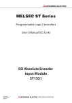
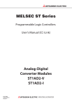
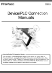
This manual describes the specifications, functions, pre-operation procedures and
troubleshooting of the ST1H-BT MELSEC-ST CC-Link head module (hereinafter referred
to as the head module).
The head module is used to connect a MELSEC-ST system to CC-Link. (It operates as a
remote device station on the CC-Link network.)
When applying a program example from this manual to the actual system, make sure to
examine the applicability of the program and confirm that it will not cause system control
problems.
Master station
GX Developer
Terminating
resistor
CC-Link
Remote device station
(MELSEC-ST system)
GX Configurator-ST
Terminating resistor
Head module
Figure 1.1 Head module overview
1-1
1
OVERVIEW
Features
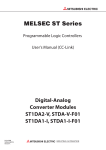
(1) Connecting MELSEC-ST system to CC-Link
Mounting this head module on a MELSEC-ST system allows connection of the
MELSEC-ST system to CC-Link.
The head module communicates with the master station, operating as a remote
device station on the CC-Link network. (
Section 4.2.1 Cyclic transmission
function)
The head module supports Ver.2 remote device stations and Ver.1 remote device
stations.
2
SYSTEM
CONFIGURATION
The head module has the following features.
3
SPECIFICATIONS
Remote device station (MELSEC-ST system)
Master station
Head module
4
Terminating resistor
Terminating resistor
Remote input
(RX)
Remote input
(RX)
Remote output
(RY)
Remote output
(RY)
Remote register
(RWw)
Remote register
(RWw)
Remote register
(RWr)
Remote register
(RWr)
Slice
module
Slice
module
5
PREPARATION AND
SETUP
Head module
6
PARAMETER SETTING
Master module
FUNCTIONS
CC-Link
Figure 1.2 Connecting MELSEC-ST system to CC-Link
7
PROGRAMMING
1.1
OVERVIEW
8
COMMANDS
1
1.1 Features
1-2
1
OVERVIEW
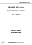
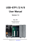
(2) Controlling MELSEC-ST system
(a) Control using I/O data
The MELSEC-ST system can be controlled with remote output (RY) and remote
register (RWw) of CC-Link.
Also, input-status data and various information of the MELSEC-ST system can be
sent to the master station using remote inputs (RX) and remote registers (RWr).
(
Section 4.2.1 Cyclic transmission function)
Slice
module
Master module
Head module
Slice
module
Remote input
(RX)
Remote input
(RX)
Input
status
Remote output
(RY)
Remote output
(RY)
Output
status
Remote register
(RWw)
Remote register
(RWw)
Output
status
Remote register
(RWr)
Remote register
(RWr)
Input
status
Figure 1.3 MELSEC-ST system control
(b) Up to 63 slice modules can be mounted
A maximum of 63 slice modules (up to 26 intelligent function modules*1) can be
mounted to the head module.
* 1 The number of mountable modules differs depending on the intelligent function module.
For details, refer to the following manual.
Manual for the intelligent function module
(c) Commands are executable from the master station (The message transmission
function is supported.)
The head module supports the message transmission function of CC-Link.
With the message transmission function (master station's dedicated instruction
(RDMSG)), commands can be executed to the head module.
The following setting or checking is available with respective commands.
• Checking the operating status of the head module and each slice module
• Checking the mounting status of each slice module
• Reading error information of the head module and each slice module
• Reading an error code of the head module or each slice module
• Reading error history of the head module
• Setting command parameters of the head module and each slice module, etc.
(d) Output status for a module error can be set
For the case where an error occurs in a slice module, whether to stop or continue
the refresh of outputs to other normal slice modules can be specified.
(
Section 4.3.1 Output status setting for module error)
1-3
1.1 Features
OVERVIEW
1
Using a separately available GX Configurator-ST, operations such as parameter
setting, system monitoring, forced output test, or online module change can be
performed easily. (
Section 2.1 Applicable Systems, GX Configurator-ST
Operating Manual)
GX Configurator-ST is connected to the RS-232 interface connector of the head
2
SYSTEM
CONFIGURATION
module.
OVERVIEW
(3) Using GX Configurator-ST
SPECIFICATIONS
3
FUNCTIONS
4
Figure 1.4 GX Configurator-ST
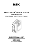
(5) Transmission speed auto-tracking
Transmission speed is automatically set according to the master module setting.
No setting is needed for the head module side.
(6) Supporting CC-Link Ver.2.00
Supporting CC-Link Ver.2.00, the head module allows flexible system construction
from a small-scale system to a large-scale system.
Large-scale system
7
PROGRAMMING
Small-scale system
6
PARAMETER SETTING
I/O modules and intelligent function modules can be replaced without stopping the
MELSEC-ST system. (
Section 4.6 Online Module Change Function)
PREPARATION AND
SETUP
5
(4) Online module change
Figure 1.5 Flexible system construction
8
COMMANDS
1
1.1 Features
1-4
1
OVERVIEW
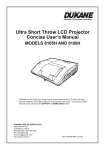
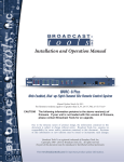
(7) Auto-optimizing number of occupied stations and extended cyclic
setting
The head module can automatically optimizes the number of occupied stations and
extended cyclic setting, according to the mounted slice modules and priority
Section 4.2.2 Auto-optimization of no. of occupied stations and
mode.*1(
extended cyclic setting)
The user does not need to calculate I/O points of the MELSEC-ST system to select
the number of occupied stations and extended cyclic setting.
The results of the optimization are indicated by the LEDs of the head module.
(
Section 5.3 (1) Operation indicator LEDs)
* 1 How to optimize the number of occupied stations and extended cyclic setting can be selected from
the following:
· Giving priority to cyclic transmission speed
· Allowing connection of more remote stations to the CC-Link system (Reducing the number of
occupied stations)
The head module optimizes the system depending on the slice modules and priority mode.
Small-scale system
1 station occupied,
single setting
Large-scale system
4 stations occupied,
quadruple setting
Figure 1.6 Optimization of No. of occupied stations and extended cyclic setting
1-5
1.1 Features
SYSTEM CONFIGURATION
1
SYSTEM CONFIGURATION
OVERVIEW
CHAPTER2
This chapter describes the system configuration for the head module.
2
SYSTEM
CONFIGURATION
Master station
GX Developer
3
SPECIFICATIONS
Terminating
resistor
CC-Link
Remote device station (MELSEC-ST system)*1
GX Configurator-ST
*2
FUNCTIONS
4
QC30R2, etc. *2
Terminating resistor
5
Head module
Figure 2.1 System configuration
PREPARATION AND
SETUP
* 1 For MELSEC-ST system configurations, refer to the following manual.
MELSEC-ST System User's Manual
* 2 For system configurations using GX Configurator-ST, refer to the following manual.
GX Configurator-ST Operating Manual
POINT
Section 4.2.2 (2) Priority modes in auto-optimization
PARAMETER SETTING
6
To use the head module as a Ver.1 remote device station, consider and modify the
points of slice modules so that the extended cyclic setting is set to single.
According to the points of the mounted slice modules, the head module
automatically optimizes the extended cyclic setting.
Remark
CC-Link dedicated cables must be prepared by the user.(
Link dedicated cable wiring)
Section 5.5.1 CC-
PROGRAMMING
7
8
COMMANDS
2
2-1
2
2.1
SYSTEM CONFIGURATION
Applicable Systems
This section describes applicable systems.
(1) Applicable master module
To execute a command for the MELSEC-ST system by a dedicated instruction
(RDMSG) of the master station, use a QJ61BT11N whose first five digits of serial No.
is 10032 or greater.
Remark
Refer to the CC-Link Cable Wiring Manual issued by the CC-Link Partner
Association.
(2) Supported software package
The software package usable for the head module is shown below.
GX Configurator-ST allows you to easily monitor the MELSEC-ST system. (GX
Configurator-ST is optional.)
Table 2.1 Supported software package
Product name
GX Configurator-ST
2-2
2.1 Applicable Systems
Model name
SWnD5C-STPB-E
Supported version
Version 1.06G or later
SPECIFICATIONS
1
SPECIFICATIONS
OVERVIEW
CHAPTER3
This chapter describes the performance specifications of the head module.
For the general specifications, refer to the following manual.
2
MELSEC-ST System User's Manual
SYSTEM
CONFIGURATION
Performance Specifications
The performance specifications of the head module are provided below.
Table 3.1 Performance specifications
Item
Transmission speed
SPECIFICATIONS
CC-Link section
CC-Link station type
3
Specification
Remote device station
(Ver.2 or Ver.1 remote device station)
156kbps/625kbps/2.5Mbps/5Mbps/10Mbps
(Auto-detected by the head module)
1 to 4 stations
By the points of the slice modules to be installed, the head module auto-optimizes the
Number of occupied stations
number of occupied stations. (
4
Section 4.2.2 Auto-optimization of no. of occupied
Single, double, quadruple, or octuple setting
By the points of the slice modules to be installed, the head module auto-optimizes the
Extended cyclic setting
extended cyclic setting. (
Section 4.2.2 Auto-optimization of no. of occupied
stations and extended cyclic setting)
Link*1
5
•RX/RY: 448 points for each
•RWw/RWr: 64 points for each
(
Section 4.2.1 (2) Cyclic transmission data size)
PREPARATION AND
SETUP
Max. points of I/O data used for CC-
•CC-Link dedicated cable
Connection cable*2
•Ver1.10 compatible CC-Link dedicated cable
•CC-Link dedicated high-performance cable
MELSEC-ST system section
Max. no. of slice modules
Max. points of I/O data available for
-
6
63 (Up to 26 intelligent function modules)*3
•
Br.n
/
Bw.n
: 252 points for each
•
Wr.n
/
Ww.n
: 52 points for each
slice module control *1
The maximum points for
Br.n
/
Bw.n
: reduce by two points for each additional
power distribution module.
Head module section
I/O points used in head module
0 point for each of input and output
•
Br.n
/
Bw.n
: 0 point for each
•
Wr.n
/
Ww.n
: 0 point for each
Number of occupied slices
2
Terminal block
Spring clamp terminal block
Applicable wire size
AWG #24 to #12, single wire: 0.5 to 1.78mm, stranded wire: 0.2 to 2.5mm2
Applicable solderless terminal
5V DC internal current consumption
7
PROGRAMMING
Number of occupied I/O points
Section 5.5.1 CC-Link dedicated cable wiring
8
0.41A
External dimensions
114.5 (H)
Weight
0.11kg
50.5 (W)
FUNCTIONS
stations and extended cyclic setting)
74.5 (D)[mm]
COMMANDS
3.1
PARAMETER SETTING
3
3.1 Performance Specifications
3-1
3
SPECIFICATIONS
* 1 For the differences between the max. points of I/O data used for CC-Link and the max. points of
I/O data available for slice module control, refer to the following.
Section 4.2.1 (3) Example of cyclic transmission data sizes
* 2 Each type of Ver.1.00 compatible CC-Link dedicated cables, Ver.1.10 compatible CC-Link
dedicated cables, and CC-Link dedicated high-performance cables must not be mixed.
If mixed, normal data transmission cannot be guaranteed.
Also, connect terminating resistors appropriate to the cable type.
* 3 The number of connectable modules differs depending on the occupied I/O points of the slice
modules installed and the intelligent function module. (
module)
3.2
Manual for the intelligent function
CC-Link Dedicated Cable Specifications
For CC-Link systems, use CC-Link dedicated cables.
The performance of the CC-Link system cannot be guaranteed when any other than CCLink dedicated cables is used.
For more information, visit the following website.
CC-Link Partner Association website (http://www.cc-link.org/)
Remark
Refer to the CC-Link Cable Wiring Manual issued by the CC-Link Partner
Association.
3-2
3.2 CC-Link Dedicated Cable Specifications
1
OVERVIEW
Communication between Master Station and MELSEC-ST
System
• Head module
Master station: Remote input (RX) and remote register (RWr)
• Master station
Head module: Remote output (RY) and remote register (RWw)
Master station
Remote device station (MELSEC-ST system)
Head module
3
SPECIFICATIONS
Terminating resistor
Terminating resistor
CC-Link
Master module
Head module
Slice
module
4
Slice
module
Br Bit input area
FUNCTIONS
Remote input (RX)
Remote input
(RX)
Input
status
3)
2)
5
PREPARATION AND
SETUP
Remote register (RWr)
Wr Word input area
Remote register
(RWr)
Remote output (RY)
Remote output
(RY)
Output
status
Bw Bit output area
4)
1)
5)
Remote register (RWw)
Ww Word output area
6
6)
PARAMETER SETTING
Remote register
(RWw)
2
SYSTEM
CONFIGURATION
The following I/O data are used for communication between the master station and
MELSEC-ST system.
Figure 3.1 Communication between master station and MELSEC-ST system
7
(Processing summary for Head module
Master station)
1) The status data of the external device are loaded into the input status area of
the slice module.
2) The input status of each slice module is stored into Br Bit input area and
Wr Word input area of the head module.
PROGRAMMING
3.3
SPECIFICATIONS
8
3) Data in Br Bit input area and Wr Word input area are sent to remote input
(RX) and remote register (RWr) of the master module.
COMMANDS
3
3.3 Communication between Master Station and MELSEC-ST System
3-3
3
SPECIFICATIONS
(Processing summary for Master station
Head module)
4) Data in remote output (RY) and remote register (RWw) are received in Bw Bit
output area and Ww Word output area of the head module.
5) Received data in Bw Bit output area and Ww Word output area are refreshed
into the output status area of each slice module.
6) The output status data of the slice module is output to the external device.
Remark
For details of each area, refer to the following.
Section 3.4 Remote I/O, Remote Registers
3-4
3.3 Communication between Master Station and MELSEC-ST System
SPECIFICATIONS
1
OVERVIEW
Remote I/O, Remote Registers
This section describes the remote I/O and remote registers of the head module.
3.4.1
List of remote I/O signals
2
SYSTEM
CONFIGURATION
(1) Configuration of remote I/O signals
Remote I/O signals are configured as shown below.
(a) Configuration of remote input signals
Br.00
3
RXm0
Bit input area
Br.01
Master module
Remote station
Remote input (RX)
Remote input (RX)
RXm1
Up to 252 points
from the first
Input data of slice
modules are stored in
order of mounted positions.
The number of available
points reduces by 2 points
for each additional power
distribution module.
Remote device station
(head module)
Remote input (RX)
RXm0
Error status,
remote station READY
Br.n-m
RXnF
16 points
from the last
MELSEC-ST system
information is stored.
Figure 3.2 Configuration of remote input signals
(b) Configuration of remote output signals
Bw.00
Bit output area
Bw.01
Remote output (RY)
Remote output (RY)
RYm1
Up to 252 points
from the first
Output data of slice
modules are stored in
order of mounted positions.
The number of available
points reduces by 2 points
for each additional power
distribution module.
Remote device station
(head module)
Remote output (RY)
Use prohibited
RYm0
RYn0
16 points
from the last
8
Error reset request
RYnF
Bw.n-m
RYnF
7
PROGRAMMING
Remote station
6
RYm0
MELSEC-ST system
information is stored.
COMMANDS
Master module
5
PREPARATION AND
SETUP
RXnF
RXn0
4
FUNCTIONS
Use prohibited
SPECIFICATIONS
3.4
PARAMETER SETTING
3
Figure 3.3 Configuration of remote output signals
3.4 Remote I/O, Remote Registers
3.4.1 List of remote I/O signals
3-5
3
SPECIFICATIONS
(2) List of remote I/O signals
Remote input (RX) represents signals input from the head module to the master
module.
Remote output (RY) represents signals output from the master module to the head
module.
Lists of remote I/O signals are shown below.
(a) Up to 252 points from the first
Data in Br Bit input area and Bw Bit output area of the slice module are stored.
The number of available points reduces by 2 points for each additional power
distribution module.
Table 3.2 List of remote I/O signals (up to 252 points from the first)
Signal direction: Head module
Device No.
Master module
Signal name
Signal direction: Master module
Device No.
RXm0
RYm0
( Br.00 )
( Bw.00 )
Input area
RXm1
RYm1
( Br.01 )
( Bw.01 )
:
:
Head module
Signal name
Output area
(b) 16 points from the last
The MELSEC-ST system information is stored.
Table 3.3 List of remote I/O signals (16 points from the last)
Signal direction: Head module
Device No.
Master module
Signal name
RXn0
( Br.(n-m)0
( Bw.(n-m)0 )
Use prohibited
to
Br.(n-m)9
Head module
Signal name
RYn0
)
to
RXn9
(
Signal direction: Master module
Device No.
Use prohibited
RYn9
)
RXnA
( Br.(n-m)A )
RXnB
( Br.(n-m)B )
( Bw.(n-m)9 )
RYnA
Error status
( Bw.(n-m)A )
Remote station READY
Error reset request
RYnB
( Bw.(n-m)B )
RXnC
to
( Br.(n-m)C )
Use prohibited
to
RXnF
(
Br.(n-m)F
Use prohibited
RYnF
)
( Bw.(n-m)F )
POINT
Do not output any "Use prohibited" remote I/O signal (do not set it to ON).
Doing so may cause the MELSEC-ST system to malfunction.
3-6
3.4 Remote I/O, Remote Registers
3.4.1 List of remote I/O signals
SPECIFICATIONS
1
In the area of up to 252 points from the first, Br Bit input area and Bw Bit output
area values of slice modules are stored. The number of available points reduces by 2
points for each additional power distribution module.
(a) Input area (from RXm0)(from "Br.00")
The Br Bit input area states of input modules and intelligent function modules
are stored.
1) Assignment order
The area is assigned in order of mounted positions of input modules and
intelligent function modules.
2) Points occupied
This area occupies the points assigned to the Br Bit input areas for input
modules and intelligent function modules.
3) Assignment example
Slice modules are mounted as shown below in the following assignment
example.
The remote input (RX) of the head module are assumed to be RX40 to RX7F.
2
Head module Bus refreshing Input module
module
Br.n = 2 points Bw.n = 2 points
Intelligent
Output module Power feeding function module
module
Br.n
= 16 points Bw.n = 16 points
Br.n
Br.01
= 4 points
Bw.n = 4 points
6
RX40
Br.00
1 2 points
RX41
RX42
Br.02
2 16 points
Remote input (RX)
Remote device station
(head module)
Br.12
RX52
7
3 4 points
Br.15
Remote input (RX)
RX55
PROGRAMMING
Remote input (RX)
Remote station
RX51
RX56
Br.16
Use prohibited
RX6F
Br.2F
RX40
8
RX70
Br.30
(2) in this
RX7F
Br.3F
section
RX7F
COMMANDS
Master module
Br.11
4
5
3
Output module Input module
3
PARAMETER SETTING
1
2
SYSTEM
CONFIGURATION
(1) Remote I/O signals assigned to the area of the first to up to 252-points
SPECIFICATIONS
The following describes details of the remote I/O signals.
OVERVIEW
Remote I/O details
FUNCTIONS
3.4.2
PREPARATION AND
SETUP
3
Figure 3.4 Input area assignment example
3.4 Remote I/O, Remote Registers
3.4.2 Remote I/O details
3-7
3
SPECIFICATIONS
(b) Output area (from RYm0)(from "Bw.00")
The Bw Bit output area states of output modules and intelligent function modules
are stored.
1) Assignment order
The area is assigned in order of mounted positions of output modules and
intelligent function modules.
2) Points occupied
This area occupies the points assigned to the Bw Bit output area for output
modules and intelligent function modules.
3) Assignment example
Slice modules are mounted as shown below in the following assignment
example.
The remote output (RY) of the head module are assumed to be RY40 to RY7F.
1
Head module
Bus refreshing Input module
module
Br.n
= 2 points
2
Output module Input module
Bw.n = 2 points
3
Intelligent
Output module Power feeding function module
module
Br.n
= 16 points Bw.n = 16 points
Br.n
RY40
Bw.00
Bw.01
= 4 points
Bw.n = 4 points
1 2 points
RY41
RY42
Bw.02
2 16 points
Bw.11
RY51
RY52
Master module
Remote station
Remote device station
(head module)
Bw.12
Remote output (RY)
Remote output (RY)
Remote output (RY)
Bw.15
RY55
Bw.16
RY56
3 4 points
Use prohibited
RY40
Bw.2F
RY6F
Bw.30
RY70
(2) in this
RY7F
Bw.3F
Figure 3.5 Output area assignment example
3-8
3.4 Remote I/O, Remote Registers
3.4.2 Remote I/O details
section
RY7F
SPECIFICATIONS
1
(2) Remote I/O signals assigned to the area of 16 points from the last
OVERVIEW
In the 16-point area from the last, MELSEC-ST system information is stored.
(a) Error status (RXnA)("Br.(n-m)A"), Error reset request (RYnA)
("Bw.(n-m)A")
• Error status (RXnA)( Br.(n-m)A ) is set to ON.
• Remote station READY (RXnB)( Br.(n-m)B ) is set to OFF.
• The ERR. LED on the head module or a slice module turns on.
2) Read the error code, identify the error cause, and take action on the problem.
3
Section 9.7.1 Reading error codes)
3) When the problem of the head module or a slice module is resolved, the
conditions will change as follows:
• Error status (RXnA)( Br.(n-m)A ) is set to OFF.
• Remote station READY (RXnB)( Br.(n-m)B ) is set to ON.
• The ERR. LED on the head module or a slice module turns off.
Error status(RXnA) ( Br.(n-m)A
4
)
FUNCTIONS
ERR. LED of head module or
each slice module
Remote station READY(RXnB)
)
5
Status of head module or
No error
each slice module
Figure 3.6 Operation when an error occurs
Error occurred
No error
PREPARATION AND
SETUP
( Br.(n-m)B
SPECIFICATIONS
(
SYSTEM
CONFIGURATION
2
1) When an error occurs, the conditions will change as follows:
PARAMETER SETTING
6
PROGRAMMING
7
8
COMMANDS
3
3.4 Remote I/O, Remote Registers
3.4.2 Remote I/O details
3-9
3
SPECIFICATIONS
4) When an error has occurred in the head module, even if the error is resolved,
the conditions will not change as described in 3). (
code list)
Section 9.7.2 Error
Set Error reset request (RYnA)( Bw.(n-m)A ) to ON to reset the error.*2
Error status (RxnA)
( Br.(n-m)A
)
or head module's ERR. LED
Remote station READY(RXnB)
( Br.(n-m)B
)
Error reset request(RYnA)
( Bw.(n-m)A
)
Head module status
No error
Error occurred
No error
Figure 3.7 When an error has occurred in the head module
* 2 Slice module errors are cleared with Error clear request (command No.: 8104H/0104H).
(b) Remote station READY (RXnB)("Br.(n-m)B")
1) This signal is set to ON when the MELSEC-ST system becomes operable.
2) This is set to OFF when an error occurs and Error status (RXnA) ( Br.(n-m)A )
is set to ON.
For the behavior of Remote station READY (RXnB)( Br.(n-m)B ), refer to the
following.
(2)(a) Error status (RXnA)("Br.(n-m)A"), Error reset request (RYnA) ("Bw.(nm)A") in this section
3 - 10
3.4 Remote I/O, Remote Registers
3.4.2 Remote I/O details
SPECIFICATIONS
1
Remote register list
OVERVIEW
(1) Configurations of remote registers
The remote registers are configured as described below.
(a) Configuration of remote register (RWr)
Wr.00
2
RWrm
Word input area
Wr.01
Remote station
Remote register
(RWr)
Remote register
(RWr)
Input data of intelligent
function modules are
stored in order of
mounted positions.
Remote device station
(head module)
Remote register
(RWr)
RWrm
Use prohibited
4
RWrn
RWrn
FUNCTIONS
Figure 3.8 Configuration of remote register
(b) Configuration of remote register (RWw)
Ww.00
RWwm
Word output area
Ww.01
Remote register
(RWw)
Remote device station
(head module)
6
Remote register
(RWw)
RWwm
PARAMETER SETTING
Remote register
(RWw)
Output data of intelligent
function modules are
stored in order of
mounted positions.
5
Use prohibited
RWwn
RWwn
7
Figure 3.9 Configuration of remote register (RWw)
PROGRAMMING
Remote station
RWw(m+1)
Points assigned to
Ww for intelligent
function modules
8
COMMANDS
Master module
3
SPECIFICATIONS
Master module
RWr(m+1)
Points assigned to
Wr for intelligent
function modules
SYSTEM
CONFIGURATION
3.4.3
PREPARATION AND
SETUP
3
3.4 Remote I/O, Remote Registers
3.4.3 Remote register list
3 - 11
3
SPECIFICATIONS
(2) Remote register list
Remote register (RWr) represents data sent from the head module to the master
module.
Remote register (RWw) represents data sent from the master module to the head
module.
The remote register list is shown below.
Table 3.4 Remote register list
Signal direction: Head module
Device No.
Master module
Signal name
RWrm
Signal direction: Master module
Device No.
RWwm
( Wr.00 )
RWr(m+1)
Intelligent function module area
(for input)
( Ww.00 )
RWw(m+1)
( Wr.01 )
( Ww.01 )
to
to
to
Wr.n
Intelligent function module area
(for output)
to
RWr(m+n)
(
RWw(m+n)
Use prohibited
)
Use prohibited
( Ww.n )
POINT
Do not write data to the "Use prohibited" area.
Doing so may cause the MELSEC-ST system to malfunction.
3 - 12
Head module
Signal name
3.4 Remote I/O, Remote Registers
3.4.3 Remote register list
SPECIFICATIONS
1
(1) Intelligent function module area (for input) (from RWrm) (from "Wr.00")
The
Wr.n
Word input area states of intelligent function modules are stored.
(a) Assignment order
The area is assigned in order of mounted positions of intelligent function modules.
(b) Points occupied
Wr.n
This area occupies the points assigned to the
intelligent function modules.
Word input areas of
(c) Assignment example
Slice modules are mounted as shown below in the following assignment example.
The remote register (RWr) of the head module are assumed to be RWr8 to RWrB.
Intelligent
Intelligent
Output module Power feeding function module function module
module
Wr.n = 2 points
Wr.n = 0 point
Ww.n = 0 point
Ww.n = 2 points
FUNCTIONS
Bus refreshing Input module
module
3
4
1
Head module
2
SYSTEM
CONFIGURATION
This section describes details of the remote registers.
OVERVIEW
Remote register details
SPECIFICATIONS
3.4.4
Remote station
Remote register
(RWr)
Remote register
(RWr)
Remote device station
(head module)
Remote register
(RWr)
Wr.00
Wr.01
6
RWr8
1 (2 points)
PARAMETER SETTING
Master module
PREPARATION AND
SETUP
5
RWr9
RWr8
RWrA
Use prohibited
RWrB
RWrB
7
PROGRAMMING
Figure 3.10 Assignment example of the intelligent function module area (for input)
8
COMMANDS
3
3.4 Remote I/O, Remote Registers
3.4.4 Remote register details
3 - 13
3
SPECIFICATIONS
(2) Intelligent function module area (for output) (from RWwm)(from
"Ww.00")
The output states of intelligent function modules are stored.
(a) Assignment order
The area is assigned in order of mounted positions of intelligent function modules.
(b) Points occupied
This area occupies the points assigned to the Ww.n Word output areas of
intelligent function modules.
(c) Assignment example
Slice modules are mounted as shown below in the following assignment example.
The remote register (RWw) of the head module are assumed to be RWw8 to
RWwB.
1
Head module
Bus refreshing
module
Intelligent
Input module Output module Power feeding Intelligent
function module function module
module
Master module
Remote station
Remote register
(RWr)
Remote register
(RWr)
Wr.n = 2 points
Wr.n = 0 point
Ww.n = 0 point
Ww.n = 2 points
Remote device station
(head module)
Remote register
(RWr)
Ww.00
1 (2 points)
Ww.01
RWw8
RWw8
RWw9
RWwA
Use prohibited
RWwB
Figure 3.11 Assignment example of the intelligent function module area (for output)
3 - 14
3.4 Remote I/O, Remote Registers
3.4.4 Remote register details
RWwB
1
(1) Processing summary for MELSEC-ST system
Master station
How input data from an external device is sent to the master station is shown below.
ON
Master station
2
SYSTEM
CONFIGURATION
This section describes the processing time of the head module used in the MELSEC-ST
system.
Communication processings between the master station and MELSEC-ST system are
indicated below.
OVERVIEW
Head Module Processing Time
3
CC-Link
Head module
SPECIFICATIONS
Link scan time
ST bus cycle time
Section 3.5.1 )
(
4
Slice module
FUNCTIONS
Input response time
ON
Input transmission delay time
Section 3.5.2 Input
(
)
transmission delay time
Figure 3.12 Processing of MELSEC-ST system
Master station
(2) Processing summary for Master station
Manual for
master module,
"Transmission delay time"
MELSEC-ST system
How output data from the master station is output to an external device is shown
6
PARAMETER SETTING
below.
ON
Master station
CC-Link
5
PREPARATION AND
SETUP
External device
Link scan time
7
Head module
ST bus cycle time
(
Section 3.5.1 )
Slice module
PROGRAMMING
3.5
SPECIFICATIONS
Output response time
8
External device
ON
Manual for master module,
"Transmission delay time"
Figure 3.13 Processing of Master station
Output transmission delay time
Section 3.5.3
(
)
MELSEC-ST system
3.5 Head Module Processing Time
3 - 15
COMMANDS
3
3
SPECIFICATIONS
3.5.1
ST bus cycle time
ST bus cycle time is the processing time required for the head module to refresh I/O data
for each slice module.
This section describes calculation formulas for ST bus cycle time and a processing time
example.
(1) Calculation formulas for ST bus cycle time
The following is a calculation formula for ST bus cycle time.
ST bus cycle time [
s] =
{44 ( 1 + 2 )} + (157
time)
No. of intelligent function modules) + (Internal processing
[1 , 2]
Calculate values for the above using the following formulas.
• When slice module(s) of 0 to 4 I/O points is mounted
1 = No. of mounted slice modules that occupy 0 to 4 I/O points*1
* 1 Include power distribution modules of 0 I/O points in the number of mounted slice modules.
• When slice module(s) of 5 or more I/O points is mounted
2 = (Occupied I/O points
4)
(No. of mounted slice modules that occupy 5
or more I/O points)
<Example>
When the following slice modules are mounted, the value for 1 + 2 is shown
below.
• Slice module of 0 I/O points: 1 module
• Slice module of 4 I/O points: 2 modules
• Slice module of 16 I/O points: 3 modules
1 + 2 = 3 + (16
4)
3= 15
[Internal processing time]
For the internal processing time, assign a value shown in the list below.
Table 3.5 Internal processing time
No. of occupied
stations
Extended cyclic setting
Single setting
1 station occupied
2 stations
occupied
Double setting
Internal processing
No. of occupied
time
stations
385
385
Extended cyclic setting
Internal processing
time
s
Single setting
415
s
s
3 stations
Double setting
445
s
occupied
Quadruple setting
520
s
Quadruple setting
400
s
Octuple setting
430
s
Octuple setting
Single setting
400
s
Single setting
430
s
Double setting
-
4 stations
Double setting
475
s
occupied
Quadruple setting
580
s
Quadruple setting
Octuple setting
460
550
s
s
Octuple setting
-
- : Not used for head module
3 - 16
3.5 Head Module Processing Time
3.5.1 ST bus cycle time
3
SPECIFICATIONS
1
The following system configuration example is used to explain a processing time
example of ST bus cycle time.
(Table 3.6 uses data of the maximum I/O points setting sheet provided in Appendix
OVERVIEW
(2) Processing time example
2
No.0
No.1
No.2
No.3
No.4
No.5
SYSTEM
CONFIGURATION
3.1.)
No.6
SPECIFICATIONS
3
4
FUNCTIONS
Figure 3.14 Processing time example of ST bus cycle time
Br.n
Bw.n
Wr.n
Ww.n
5V DC internal
current consumption
(Total)
24V DC
current
(Total)
Slot width (Total)
-
0
0(2)
ST1H-BT
0
0
0
0
0.410A(0.410A)
0A(0A)
1
2(1)
ST1PSD
0
0
0
0
-
-
2
3(1)
ST1X2-DE1
2
0
0
0
0.085A(0.495A)
*1
3
4(1)
ST1Y2-TE2
0
2
0
0
0.090A(0.585A)
*1
4
5(1)
ST1PDD
0
0
0
0
0.060A(0.645A)
-
5
6(2)
ST1AD2-V
4
4
2
0
0.110A(0.755A)
*1
6
8(2)
ST1DA2-V
4
4
0
2
0.095A(0.850A)
*1
10
10
2
2
-
-
Total
(252 bits
or less)*2
(252 bits
or less)*2
(52 words
or less)
25.2mm
(25.2mm)
12.6mm
(37.8mm)
12.6mm
(50.4mm)
12.6mm
(63.0mm)
12.6mm
(75.6mm)
12.6mm
(88.2mm)
5
PREPARATION AND
SETUP
Module name
6
7
88.2mm
(52 words
or less)
Total
(850mm or less)
* 1 The 24V DC current varies depending on the external device connected to each slice module.
Check the current consumption of the external device connected to each slice module, and
8
COMMANDS
calculate the total value. (
MELSEC-ST System User's Manual)
* 2 The available points will decrease by two points for each additional power distribution module.
PROGRAMMING
Slice
position No.
PARAMETER SETTING
Table 3.6 I/O points sheet
Start slice No.
(No. of occupied
slices)
3.5 Head Module Processing Time
3.5.1 ST bus cycle time
3 - 17
3
SPECIFICATIONS
Number of mounted intelligent function modules: 2
Number of occupied stations: 1*3
Extended cyclic setting: Single setting*3
* 3 In the above system, the number of occupied stations and extended cyclic setting are optimized to
1 station occupied and single setting respectively. (
occupied stations and extended cyclic setting)
ST bus cycle time = {44
3 - 18
3.5 Head Module Processing Time
3.5.1 ST bus cycle time
(6 + 0)} + (157
Section 4.2.2 Auto-optimization of no. of
2) + 385
963 [
s]
SPECIFICATIONS
1
This section explains the time taken from when a slice module receives input data from an
external device until the module outputs the data to the CC-Link network.
OVERVIEW
Input transmission delay time
2
(1) Average delay time
(Input response time) + (1.5
ST bus cycle time)
[Input response time]
• For input modules
MELSEC-ST System User's Manual)
Processing time of an intelligent function module (
function module)
3
Manual for the intelligent
SPECIFICATIONS
Response time of an input module (
• For intelligent function modules
SYSTEM
CONFIGURATION
Input transmission delay time =
[ST bus cycle time]
Section 3.5.1 ST bus cycle time
4
[Link scan time]
Manual for the master module, "Link scan time"
FUNCTIONS
(2) Maximum delay time
Input transmission delay time =
ST bus cycle time) + (Link scan time)
5
[Input response time]
• For input modules
Response time of an input module (
• For intelligent function modules
MELSEC-ST System User's Manual)
Processing time of an intelligent function module (
function module)
Manual for the intelligent
PREPARATION AND
SETUP
(Input response time) + (2.0
6
PARAMETER SETTING
[ST bus cycle time]
Section 3.5.1 ST bus cycle time
[Link scan time]
Manual for the master module, "Link scan time"
7
PROGRAMMING
3.5.2
8
COMMANDS
3
3.5 Head Module Processing Time
3.5.2 Input transmission delay time
3 - 19
3
SPECIFICATIONS
3.5.3
Output transmission delay time
This section explains the time taken from when the head module receives output data from
the master station until a slice module outputs the data to an external device.
(1) Average delay time
Output transmission delay time = (ST bus cycle time) + (Output response time)
[ST bus cycle time]
Section 3.5.1 ST bus cycle time
[Output response time]
• For output modules
Response time of an output module (
"Output module specifications")
• For intelligent function modules
MELSEC-ST System User's Manual,
Processing time of an intelligent function module (
function module)
Manual for the intelligent
(2) Maximum delay time
Output transmission delay time = (1.5
ST bus cycle time) + (Output response time)
[ST bus cycle time]
Section 3.5.1 ST bus cycle time
[Output response time]
• For output modules
Response time of an output module (
"Output module specifications")
• For intelligent function modules
MELSEC-ST System User's Manual,
Processing time of an intelligent function module (
function module)
3 - 20
3.5 Head Module Processing Time
3.5.3 Output transmission delay time
Manual for the intelligent
4
FUNCTIONS
1
OVERVIEW
FUNCTIONS
This chapter describes the functions of the head module.
4.1
2
Function List
SYSTEM
CONFIGURATION
The functions of the head module are listed below.
(1) CC-Link functions
Table 4.1 CC-Link functions
Function
Auto-optimization of no. of
occupied stations and
extended cyclic setting
Transmission speed autotracking function
Consistency function
section
Periodical data communications are performed between the master station and head module
using RX, RY, RWr, and RWw of CC-Link.
The head module optimizes the number of occupied stations and extended cyclic setting
depending on the mounted slice modules.
Transmission speed is automatically set according to the master module setting.
Integrity of cyclic data is ensured.
Section 4.2.1
Section 4.2.2
4
Section 4.2.3
(2) RAS functions
Table 4.2 RAS functions
Operation method
GX
ConfiguratorST
Description
Command
Buttons or
switches on
head module
Reference
section
For the case where an error occurs in a slice
module, this function allows setting of whether to
stop or continue refreshing of the following data to
Section 4.3.1
modules.
Bw.n
Bit output area)
•Remote register (RWw)( Ww.n
6
PARAMETER SETTING
•Remote output (RY)(
Word output
area)
7
PROGRAMMING
module error
other normal output modules and intelligent function
8
COMMANDS
Output status setting for
5
PREPARATION AND
SETUP
Function
3
FUNCTIONS
Cyclic transmission
Reference
Description
SPECIFICATIONS
CHAPTER4
4.1 Function List
4-1
4
FUNCTIONS
(3) Monitoring functions
Table 4.3 Monitoring functions
Operation method
Function
Description
GX
ConfiguratorST
Command
Buttons or
switches on
head module
Various information of the head module and slice
Information monitoring
The operating status of each slice module and error
Section 4.4.1
history of the head module can be monitored.
Data of
I/O data monitoring
Wr
function
Br
section
*1
modules can be monitored.
Status monitoring
Reference
Bit input area, Bw Bit output area,
*1
Word input area, and Ww Word output area
can be monitored.
* 1 For GX Configurator-ST operations, refer to the following manual.
GX Configurator-ST Operating Manual
(4) Test functions
Table 4.4 Test functions
Operation method
Function
Description
Forced output test function
Slice module data in
Command
Buttons or
switches on
head module
Bit output area and
Reference
section
*1
Word output area can be forcibly output.
Ww.n
Self-diagnostic function
Bw.n
GX
ConfiguratorST
The head module can perform a hardware test by
Section 5.4
itself.
* 1 For GX Configurator-ST operations, refer to the following manual.
GX Configurator-ST Operating Manual
(5) Other functions
Table 4.5 Other functions
Operation method
Function
Description
Reading/writing intelligent
function module
or RAM of an intelligent function module.
parameters
Online module change
Reset function of head
module
Command execution
4-2
Parameters can be read from or written to the ROM
I/O modules and intelligent function modules can be
replaced without stopping the MELSEC-ST system.
The MELSEC-ST system can be reset.
Commands requested by message transmission
from the master station can be executed.
4.1 Function List
GX
ConfiguratorST
Command
Buttons or
switches on
head module
Reference
section
Section 4.5
Section 4.6
Section 5.3.3
CHAPTER 8
1
OVERVIEW
CC-Link Functions
This section describes the functions of the head module used in CC-Link.
Cyclic transmission function
(1) About cyclic transmission function
This function allows periodical data communication between the master station and
head module using RX, RY, RWr, and RWw of CC-Link.
Master station
Remote device station (MELSEC-ST system)
SYSTEM
CONFIGURATION
2
3
SPECIFICATIONS
Head module
Terminating resistor
4
Terminating resistor
CC-Link
Master module
Head module
Slice
module
Slice
module
Remote input (RX)
Remote input
(RX)
Br Bit input area
Input
status
Cyclic
transmission
Remote output (RY)
Remote register
(RWw)
Remote register (RWw)
Ww Word output area
Bw Bit output area
Output
status
6
PARAMETER SETTING
Remote output
(RY)
5
PREPARATION AND
SETUP
Remote register (RWr)
Wr Word input area
Remote register
(RWr)
FUNCTIONS
4.2.1
7
Figure 4.1 Cyclic transmission function
PROGRAMMING
4.2
FUNCTIONS
8
COMMANDS
4
4.2 CC-Link Functions
4.2.1 Cyclic transmission function
4-3
4
FUNCTIONS
(2) Cyclic transmission data size
(a) I/O points available for slice module control
Using the following points, slice modules can be controlled.
Table 4.6 I/O points available for slice module control
Item
Point
Br.n
Bit input area
Up to 252 points*1
Bw.n
Bit output area
Up to 252 points*1
Wr.n
Word input area
Up to 52 points
Ww.n
Word output area
Up to 52 points
* 1 The available points will decrease by two points for each additional power distribution module.
Remark
(1) For I/O points, refer to the following.
Section 5.2.1 Checking the MELSEC-ST system
(2) For details of each area, refer to the following.
Section 3.4 Remote I/O, Remote Registers
(b) Points that the head module uses for CC-Link
Depending on the mounted slice module, the number of occupied stations and
extended cyclic setting are automatically optimized. (
Section 4.2.2 Autooptimization of no. of occupied stations and extended cyclic setting)
The following table shows cyclic transmission data sizes by combinations of the
number of occupied stations and extended cyclic setting.
Table 4.7 Points that head module uses for CC-Link
Item
Extended cyclic setting
Single
Double
Quadruple
Octuple
32 points
32 points
64 points
128 points
Remote register (RWr, RWw)
4 points
8 points
16 points
32 points
Remote I/O (RX, RY)
64 points
-
192 points
384 points
-
32 points
64 points
160 points
320 points
-
24 points
48 points
-
128 points
224 points
448 points
-
16 points
32 points
64 points
-
1 station
Remote I/O (RX, RY)
occupied
2 stations
occupied
Remote register (RWr, RWw)
8 points
3 stations
Remote I/O (RX, RY)
96 points
occupied
Remote register (RWr, RWw)
12 points
4 stations
Remote I/O (RX, RY)
occupied
Remote register (RWr, RWw)
- : Not available for head module
4-4
4.2 CC-Link Functions
4.2.1 Cyclic transmission function
4
FUNCTIONS
1
This section gives an example of cyclic transmission data sizes used in the following
system configuration.
(a) System configuration example
2
Table 4.8 System configuration example
Wr.n
0
0
0
0
1
ST1PSD
0
0
0
0
2
ST1X2-DE1
2
0
0
0
3
ST1Y2-TE2
0
2
0
0
4
ST1PDD
0
0
0
0
5
ST1AD2-V
4
4
2
0
6
ST1AD2-V
4
4
2
0
7
ST1AD2-V
4
4
2
0
8
ST1AD2-V
4
4
2
0
13
ST1RD2
4
4
2
0
14
ST1RD2
4
4
2
0
15
ST1SS1
4
4
2
0
16
ST1SS1
Total
Ww.n
4
4
2
0
34
34
16
0
3
SPECIFICATIONS
Bw.n
ST1H-BT
4
(b) Number of occupied stations and extended cyclic setting
In the above system configuration, the number of occupied stations and extended
cyclic setting is as follows (When the mode switch is default):
• No. of occupied stations: 3 stations occupied
• Extended cyclic setting: Double setting
Section 4.2.2 Auto-optimization of no. of occupied stations and extended
cyclic setting
(c) Cyclic transmission data sizes
The data sizes are as shown below.
Remote I/O (RX, RY)
Remote I/O (RX, RY)
, Bw.n
Use prohibited
MELSEC-ST system
information
Br.n
, Bw.n
34 points
Points described
in (2) (a)
Use prohibited
110 points
MELSEC-ST system
information
16 points
7
160 points
Points described
in (2) (b)
8
Figure 4.2 Cyclic transmission data sizes (Remote input/output (RX, RY))
COMMANDS
Br.n
PARAMETER SETTING
Head module
5
6
1) Remote input/output (RX, RY)
Master module
FUNCTIONS
Br.n
0
SYSTEM
CONFIGURATION
Word
PREPARATION AND
SETUP
Bit
Module name
PROGRAMMING
No.
OVERVIEW
(3) Example of cyclic transmission data sizes
4.2 CC-Link Functions
4.2.1 Cyclic transmission function
4-5
4
FUNCTIONS
2) Remote register (RWr)
Master module
Head module
Remote register (RWr)
Remote register (RWr)
Wr.n
Wr.n
16 points
Points described
in (2) (a)
24 points Points described
in (2) (b)
Use prohibited
Use prohibited
8 points
Figure 4.3 Cyclic transmission data sizes (Remote register (RWr))
Remark
For details of each area, refer to the following.
Section 3.4 Remote I/O, Remote Registers
(4) Setting method
For the setting method, refer to the following.
Section 5.3.1 Mode switch
4-6
4.2 CC-Link Functions
4.2.1 Cyclic transmission function
FUNCTIONS
1
Auto-optimization of no. of occupied stations and extended cyclic
setting
(1) About the auto-optimization of no. of occupied stations and extended
cyclic setting
The head module automatically optimizes the number of occupied stations and
OVERVIEW
4.2.2
2
SYSTEM
CONFIGURATION
extended cyclic setting depending on the mounted slice modules.
The head module optimizes the system depending on the slice modules and priority mode.
Small-scale system
Large-scale system
3
SPECIFICATIONS
4 stations occupied,
quadruple setting
Figure 4.4 Auto-optimization of no. of occupied stations and extended cyclic setting
(2) Priority modes in auto-optimization
4
Priority high speed mode or Priority min. stations mode can be selected for
optimization of the number of occupied stations and extended cyclic setting.
(a) Priority high speed mode
This mode gives priority to the cyclic transmission speed to set the number of
occupied stations and extended cyclic setting.
The optimization will make the extended cyclic setting value smaller.
5
PREPARATION AND
SETUP
52
4 stations occupied,
quadruple setting
43
42
3 stations occupied,
quadruple setting
29
28
6
PARAMETER SETTING
4 stations occupied,
double setting
21
20
3 stations occupied,
double setting
15
14
4 stations occupied,
single setting
11
10
7
3 stations occupied,
single setting
7
6
PROGRAMMING
2 stations occupied,
single setting
3
2
1 station occupied,
single setting
0
0
16 17
48 49
FUNCTIONS
1 station occupied,
single setting
80 81
112 113
144 145
208 209
8
252
Points of Br.n Bit input area or Bw.n Bit output area [bits]
: Head module can be used only as Ver.1 remote device station.
: Head module can be used only as Ver.2 remote device station.
Figure 4.5 No. of occupied stations and extended cyclic setting in Priority high speed mode
4.2 CC-Link Functions
4.2.2 Auto-optimization of no. of occupied stations and extended cyclic setting
4-7
COMMANDS
Points of Wr.n Word input area or Ww.n Word output area [words]
4
4
FUNCTIONS
(b) Priority min. stations mode
This mode optimizes the number of occupied stations and extended cyclic setting
so that the number of remote stations connectable to the CC-Link system can be
increased.
Points of Wr.n Word input area or Ww.n Word output area [words]
The optimization will reduce the number of occupied stations.
52
2 stations occupied,
octuple setting
27
26
2 stations occupied,
quadruple setting
25
1 station occupied,
octuple setting
11
10
1 station occupied,
quadruple setting
5
4
1 station occupied,
double setting
3
2
1 station occupied,
single setting
0
16 17
48 49
112 113
176 177
252
Points of Br.n Bit input area or Bw.n Bit output area [bits]
: Head module can be used only as Ver.1 remote device station
; Head module can be used only as Ver.2 remote device station.
Figure 4.6 No. of occupied stations and extended cyclic settings in Priority min. stations mode
POINT
For a Ver.1 remote device station, use Priority high speed mode. (
(2)(a)
Priority high speed mode in this section)
In Priority min. stations mode, only a combination of 1 station occupied and single
setting is available for Ver.1 remote device stations.
(3) Setting method
For the setting method, refer to the following.
Section 5.3.1 Mode switch
4-8
4.2 CC-Link Functions
4.2.2 Auto-optimization of no. of occupied stations and extended cyclic setting
FUNCTIONS
1
An optimization example in the following system configuration is described below.
(a) System configuration example
Table 4.9 System configuration example
2
Word
Br.n
Bw.n
Wr.n
Ww.n
0
ST1H-BT
0
0
0
0
1
ST1PSD
0
0
0
0
2
ST1X2-DE1
2
0
0
0
3
ST1Y16-TE2
0
16
0
0
4
ST1PDD
0
0
0
0
5
ST1AD2-V
4
4
2
0
6
ST1DA2-V
4
4
0
2
7
ST1TD2
4
4
2
0
14
28
4
2
Total
SYSTEM
CONFIGURATION
Bit
Module name
3
SPECIFICATIONS
No.
OVERVIEW
(4) Optimization example
(b) Priority mode
Priority high speed mode is used.
4
(c) Optimization result
Bit output area, the greater
Word input area and Ww.n Word output area, the
greater value of 4 points is used.
PREPARATION AND
SETUP
5
Optimized to "2 stations occupied,
single setting".
11
10
PARAMETER SETTING
4
6
3 stations occupied,
single setting
7
6
2 stations occupied,
single setting
3
2
1 station occupied,
single setting
0
0
16 17
48 49
7
80 81
28
Points of Br.n Bit input area or Bw.n Bit output area [bits]
Figure 4.7 Optimization result
(5) Precautions
When using the head module as a Ver.1 remote device station, consider the point
setting for slice modules so that the extended cyclic setting will be single setting.
• Extended cyclic setting is single setting: Operates as a Ver.1 remote device
station.
• Extended cyclic setting is double setting or more: Operates as a Ver.2 remote
device station.
4.2 CC-Link Functions
4.2.2 Auto-optimization of no. of occupied stations and extended cyclic setting
4-9
PROGRAMMING
Wr.n
8
COMMANDS
From the values of
Bw.n
FUNCTIONS
From the values of Br.n Bit input area and
value of 28 points is used.
Points of Wr.n Word input area or
Ww.n Word output area [words]
4
4
FUNCTIONS
4.2.3
Consistency function
(1) About the consistency function
This function ensures cyclic data integrity.
When consistency function is disabled
Master module
Head module
1
3
B
D
Data output before
completion of data
transfer
0
1
3
5
7
2
A
C
0
2
4
6
Data being
transferred
: Updated with data transferred from master module
: Not updated with data transferred from master module
When consistency function is enabled
Head module
Data output after
completion of data
transfer
1
3
5
7
Master module
0
2
4
6
1
3
5
7
0
2
4
6
Data transfer
completed
: Updated with data transferred from master module
: Not updated with data transferred from master module
Figure 4.8 Consistency function
When an intelligent function module uses I/O data, enable the consistency function.
4 - 10
4.2 CC-Link Functions
4.2.3 Consistency function
FUNCTIONS
1
(2) Setting method
OVERVIEW
Perform the following setting.
(
Manual for the master module, "Guaranteeing the cyclic data for each slave
station (block guarantee of cyclic data per station)")
(b) Head module side
With a command parameter of the head module, enable the consistency function.
1) Settings
Table 4.10 Consistency function (Command parameter of head module)
3
Enable (Default)
Ensures cyclic transmission data integrity.
Disable
Does not ensure cyclic transmission data integrity.
SPECIFICATIONS
Description
2) Setting method
Use a command for the setting.
Section 8.2.7 Initial data batch write request (Command No.: 8106H),
Section 8.2.8 Initial data individual write request (Command No.: 8107H/
0107H)
POINT
5
PREPARATION AND
SETUP
Setting the consistency function to "Disable" will reduce intelligent function
module control operation by one ST bus cycle time.
4
FUNCTIONS
Item
2
SYSTEM
CONFIGURATION
(a) Master station side
Enable the Block guarantee of cyclic data per station.
PARAMETER SETTING
6
PROGRAMMING
7
8
COMMANDS
4
4.2 CC-Link Functions
4.2.3 Consistency function
4 - 11
4
4.3
FUNCTIONS
RAS Functions
This section describes the RAS functions of the head module.
4.3.1
Output status setting for module error
(1) About the output status setting for module error
For the case where an error occurs in a slice module (except power distribution
modules), this function allows setting of whether to stop or continue refreshing of the
following data to other normal output modules and intelligent function modules.
• Remote output (RY) (
Bw.n
Bit output area)
• Remote register (RWw) ( Ww.n Word output area)
(2) Operating conditions for the output status setting for module error
This function is activated in the following cases:
• A slice module failed to respond due to a hardware fault.
• A slice module was illegally removed while the external power supply is ON.
(3) The I/O status after error occurrence
(a) When a CC-Link communication error has occurred between the master station
and head module
The I/O states of normally operating slice modules are shown below.
Table 4.11 I/O status after error occurrence
Type
I/O status of slice module
Slice module
(RUN LED flashing (at 1s intervals))
Output module
Output
Hold/Clear
Hold/Clear/Preset*1
Intelligent function module
Input module
Input
Refresh*2
Intelligent function module
* 1 The I/O status differs depending on the status of
Bw.n
Bit output area before the error
occurred. (
Manual for the intelligent function module, "Combinations of various functions")
* 2 The I/O status on the master station side differs depending on the master station's network
parameter (Data link disorder station setting).
(
4 - 12
Manual for the master module, "Section 5.5 Station Status at Error Occurrence")
4.3 RAS Functions
4.3.1 Output status setting for module error
4
FUNCTIONS
1
OVERVIEW
(b) When an error occurred in another slice module
The I/O states of normally operating slice modules are shown below.
When "Continue" is selected*1
(RUN LED flashing (at 1s intervals)
(RUN LED ON)
Hold/Clear*2
Intelligent function module
Refresh
Hold/Clear/Preset*2*3
Input module
Refresh
Intelligent function module
Refresh
* 1 This is set for the head module. (
(4) Setting method in this section)
* 2 If another slice module with an error is replaced with a normal one by online module change, the
Clear/Hold/Preset is reset to the refresh status (the RUN LED is ON) upon completion of online
module change.
* 3 The I/O status differs depending on the status of
occurred. (
Bw.n
Bit output area before the error
Manual for the intelligent function module, "Combinations of various functions")
POINT
(1) The output status of the slice module in which an error has occurred is the
status set with a command parameter of each slice module.
(2) Remote input (RX) (
Br.n
3
4
Bit input area) and remote register (RWr)
( Wr.n Word input area) continues refresh even if an error occurs in a slice
module.
FUNCTIONS
Output module
2
PREPARATION AND
SETUP
5
6
PARAMETER SETTING
Input
When "Stop" is selected*1
7
PROGRAMMING
Output
Slice module
8
COMMANDS
Type
SYSTEM
CONFIGURATION
I/O status of slice module
SPECIFICATIONS
Table 4.12 The I/O status when an error occurred in another slice module
4.3 RAS Functions
4.3.1 Output status setting for module error
4 - 13
4
FUNCTIONS
(4) Setting method
To use the output status setting for module error, set the output status parameter for
module error for the head module.
(a) Setting items
Table 4.13 Setting items for the output status setting for module error
Item
Description
RUN LED of slice module
When a slice module is faulty, the following data of normally operating output
modules and intelligent function modules are placed in the status set with a
Stop (Default)
command parameter of each slice module *1.
•Remote output (RY) (
Bw.n
Flashing (at 1s intervals)
Bit output area)
•Remote register (RWw) ( Ww.n
Word output area)
When a slice module is faulty, the following data refresh of normally operating
output modules and intelligent function modules are continued.
Continue
•Remote output (RY) (
Bw.n
Bit output area)
•Remote register (RWw) ( Ww.n
On
Word output area)
* 1 For command parameters of output modules and intelligent function modules, refer to the following
manual.
Manuals for the output module and intelligent function module
(b) Setting method
Set the output status for module error with a command parameter.
Section 8.2.7 Initial data batch write request (Command No.: 8106H)
Section 8.2.8 Initial data individual write request (Command No.: 8107H/
0107H)
4 - 14
4.3 RAS Functions
4.3.1 Output status setting for module error
1
Monitoring Function
OVERVIEW
4.4
FUNCTIONS
This section describes the monitoring function of the head module.
4.4.1
Status monitoring function
2
(1) About the status monitoring function
The operating status of each slice module and error history of the head module can
be monitored with GX Configurator-ST.
Information of some items can be monitored using commands or I/O data.
SYSTEM
CONFIGURATION
4
3
<System Monitor>
SPECIFICATIONS
<Monitoring intelligent function module>
FUNCTIONS
4
5
PREPARATION AND
SETUP
<Monitoring head module>
The I/O data status can be checked.
The operating status of
each module can be
checked.
Current error code can be checked.
6
PARAMETER SETTING
Error history can be viewed.
Figure 4.9 Status monitoring using GX Configurator-ST
7
Remark
PROGRAMMING
For details of GX Configurator-ST, refer to the following manual.
GX Configurator-ST Operating Manual
COMMANDS
8
4.4 Monitoring Function
4.4.1 Status monitoring function
4 - 15
4
FUNCTIONS
(2) Monitorable items
The following table lists a variety of information that can be monitored with the status
monitoring function.
Table 4.14 Monitorable items
Monitoring method
Item
Status of
Br
GX
Check by I/O
Configurator-ST
data
Command
Bit input area, Bw Bit output area, Wr
Word input area, and Ww Word output area)
Installation status of each module
Presence/absence of an error in MELSEC-ST system
Identification of slice No. corresponding to an error
Error code for error occurred in each module
Error history of head module
: Monitorable,
4 - 16
4.4 Monitoring Function
4.4.1 Status monitoring function
: Not monitorable
1
OVERVIEW
Reading/Writing Intelligent Function Module Parameters
(1) About reading and writing intelligent function module parameters
Command parameters can be read from or written to the ROM or RAM of an
intelligent function module.
2
To read or write command parameters from or to an intelligent function module, use
either of the following.
(a) GX Configurator-ST
Read or write command parameters with GX Configurator-ST.
SYSTEM
CONFIGURATION
(2) Parameter reading or writing operation
(b) Commands
Execute a command with a dedicated instruction (RDMSG) of the master station
to read or write command parameters.
The command to be used varies depending on the set command parameters.
SPECIFICATIONS
3
4
Remark
For details, refer to the following manual.
FUNCTIONS
Manual for the intelligent function module
PREPARATION AND
SETUP
5
PARAMETER SETTING
6
7
PROGRAMMING
4.5
FUNCTIONS
8
COMMANDS
4
4.5 Reading/Writing Intelligent Function Module Parameters
4 - 17
4
4.6
FUNCTIONS
Online Module Change Function
(1) About the online module change function
I/O modules and intelligent function modules can be replaced without stopping the
MELSEC-ST system.
Online module change is executable by operating the buttons on the head module or
from GX Configurator-ST.
4.6.1
Precautions for online module change
The following are the precautions for online module change.
(1) System configuration in which online module change is executable
To perform the online module change, the system configuration must be appropriate
for execution of the online module change. (
MELSEC-ST System User's Manual,
"Precautions for System Configuration")
Executing the online module change in an inappropriate system configuration may
result in a malfunction or failure.
In a system configuration where online module change is not allowed, shut off all
phases of the external power supply for the MELSEC-ST system to replace a slice
module.
(2) Online module change procedure
Be sure to perform an online module change by the procedure described below.
Failure to do so can cause a malfunction or failure.
Section 4.6.2 Online module change procedure
(3) External devices at online module change
Before starting online module change, confirm that the external device connected to
the slice module to be removed does not malfunction.
Also, it is recommended to set 0 (OFF) in the Bw.n Bit output area and Ww.n
Word output area of the slice module before replacement.
(4) Replaceable slice module
I/O modules and intelligent function modules only can be replaced by online module
change.
Power distribution modules and base modules cannot be replaced online.
Before installing or removing a power distribution module or base module, shut off all
phases of the external power supply.
Failure to do so may damage all of the MELSEC-ST system modules.
(5) Number of replaceable slice modules
Only one slice module can be replaced in a single online module change.
To replace multiple slice modules, perform a separate online module change for each
module.
4 - 18
4.6 Online Module Change Function
4.6.1 Precautions for online module change
FUNCTIONS
1
Only the slice modules of the same model name can be replaced online.
Replacing a slice module with a different slice module model and adding a new slice
module is not allowed.
OVERVIEW
(6) Replaceable slice module
While an online module change is being executed (while the REL. LED of the head
module is on), no command can be executed to the slice module being replaced
online.
An attempt to execute a command to the slice module in such a case will cause an
error.
SYSTEM
CONFIGURATION
2
(7) Command execution during online module change
3
(9) The ERR. LED of the head module in online module change status
The ERR. LED of the head module in online module change status will turn on only
when an error related to the online module change occurs.
It will not turn on or flash when any other error occurs.
(10)I/O data during online module change
Bit input area
•
Wr.n
Word input area
(11)When Hold is set for the Clear/Hold setting
If an output module, for which "Hold" is set in the Clear/Hold setting, is replaced online
while communication with the master station is disconnected, the
area value is set to 0 (OFF).
Even after this online change is completed, the
return to the value held.
Bw.n
Bw.n
Bit output
Bit output area value will not
6
PARAMETER SETTING
Br.n
7
(12)Forced output test during online module change
The forced output test cannot be performed for a slice module in online module
change status.
After completion of the online module change, perform the forced output test.
PROGRAMMING
•
5
PREPARATION AND
SETUP
While online module change is being executed for a slice module (while the REL. LED
of the head module is on), the following data of the slice module are all set to 0 (OFF).
4
FUNCTIONS
When changing a command parameter of the slice module, which is being replaced
online (the head module's REL. LED is on), from the master station, wait until the
online module change is completed.
SPECIFICATIONS
(8) Parameter change during online module change
8
COMMANDS
4
4.6 Online Module Change Function
4.6.1 Precautions for online module change
4 - 19
4
FUNCTIONS
4.6.2
Online module change procedure
This section explains the online module change procedure.
Observe the following procedure.
Start
Is online module change
executable in the system? *1
No
Yes
No
Prepared for online
module change? *2
Yes
No
Can the external device
be disconnected? *3
Online module change is not executable. Shut off all
phases of the external power supply in
the MELSEC-ST system, and replace the slice module.
Yes
Execution of online module change
Preparation for slice module replacement
Using the buttons on the head module
Using GX Configurator-ST
Section 4.6.3 (a), (b)
Section 4.6.4 (a) to (c)
*3
Disconnection from the external device
Refer to each slice module manual.
Slice module replacement
Using the buttons on the head module
Using GX Configurator-ST
Connection of the external device after slice module replacement
Refer to each slice module manual.*3
Operations after external device connection
Using the buttons on the head module
Using GX Configurator-ST
Section 4.6.3 (d), (e)
Section 4.6.4 (e), (f)
Section 4.6.3 (g), (h)
Section 4.6.4 (h) to (j)
Completed
*1
*2
*3
MELSEC-ST System User's Manual, "3.4 Precautions for System Configuration"
Each slice module manual, "Preparation for Online Module Change"
Each slice module manual, "Disconnecting/connecting the External Device for Online Module Change"
Figure 4.10 Online module change procedure
4 - 20
4.6 Online Module Change Function
4.6.2 Online module change procedure
FUNCTIONS
1
This section explains how to perform online module change using the buttons on the head
module.
OVERVIEW
Online module change using the buttons on the head module
(a) Specify a slice module to be replaced online.
Press the + (plus) button.
• When the + (plus) button is pressed, the RUN LED on the bus refreshing
module next to the right of the head module starts flashing (at 0.25s
intervals).
• Press the + (plus) or - (minus) button until the RUN LED of the target module
SYSTEM
CONFIGURATION
2
[Preparation for slice module replacement]
3
SPECIFICATIONS
flashes (at 0.25s intervals)*1.
FUNCTIONS
4
To stop the online module change, press the + (plus) or - (minus) button until the
RUN LED on the head module flashes (at 0.25s intervals).
For the + and - button operations, refer to Remarks on the next page.
* 1 If the RUN LED does not flash, check whether the RUN LED on another slice module (for example,
a slice module on the right or left to the target module) flashes (at 0.25s intervals) or not.
Alternatively perform online module change from GX Configurator-ST.
If the RUN LED of the target slice module does not flash (at 0.25s intervals) after taking the above
actions, the slice module may have a hardware fault.
6
PARAMETER SETTING
Figure 4.11 Specifying a slice module
PREPARATION AND
SETUP
5
Head module
7
PROGRAMMING
4.6.3
8
COMMANDS
4
4.6 Online Module Change Function
4.6.3 Online module change using the buttons on the head module
4 - 21
4
FUNCTIONS
Remark
The following explains how to operate the + and - buttons of the head module.
No.0
No.1
No.2
No.3
No.4
No.5
No.6
<When the + button is pressed>
1) When the + button is pressed, the RUN LED of No.1 (bus refreshing
module on the right next to the head module) starts flashing (at 0.25s intervals).
2) With each press of the + button, the RUN LED of each module flashes
(at 0.25s intervals) in turn in order from No.2 to No.6.
3) If the button is pressed while the RUN LED of No.6 is flashing,
the head module has a turn.
However, the RUN LED status of the head module does not change.
<When the - button is pressed>
1) When the - button is pressed, the RUN LED of No.6 (the rightmost
slice module in the MELSEC-ST system) starts flashing (at 0.25s intervals).
2) With each press of the - button, the RUN LED of each module starts
flashing (at 0.25s intervals) in order from No.5 to No.1.
RUN LEDs flash in turn in this order (with + button)
3) If the button is pressed while the RUN LED of No.1 is flashing,
the head module has a turn.
However, the RUN LED status of the head module does not change.
RUN LEDs flash in turn in this order (with - button)
Figure 4.12 The + and - buttons
(b) Press the RELEASE button on the head module until the REL. LED turns on.
Hold down the RELEASE
button until the head
module's REL. LED turns
on and the RUN LED of
the module to be
replaced turns off.
Figure 4.13 The REL. LED turns on.
When the REL. LED turns on, command parameters are transferred from the slice
module to be replaced online and saved into the head module.
The following conditions indicate that the module change is ready for online
module change after processing the RELEASE button.
• The REL. LED on the head module turns on.*2
• The RUN LED on the slice module to be replaced online turns off.
* 2 If the REL. and ERR. LEDs turned on, an error may have occurred during online module change.
Identify the error and take action. (
4 - 22
Section 9.7 Error Codes)
4.6 Online Module Change Function
4.6.3 Online module change using the buttons on the head module
FUNCTIONS
1
[Disconnection from the external device]
change is performed. (
OVERVIEW
(c) Disconnect the external device from the slice module for which online module
Manual for the slice module, "Disconnecting/
Connecting the External Device for Online Module Change")
2
Switch
SYSTEM
CONFIGURATION
ON
OFF
3
SPECIFICATIONS
External
device
Figure 4.14 Disconnection from the external device
POINT
[Slice module replacement]
FUNCTIONS
4
When the external device cannot be disconnected as instructed in the slice
module manual, shut off all phases of the external power supply for the MELSECST system and then replace the slice module.
5
(e) Install a new slice module of the same model name as the removed one to the
base module.
PREPARATION AND
SETUP
(d) Remove the slice module to be replaced online from the base module.
PARAMETER SETTING
6
Replace
PROGRAMMING
7
Figure 4.15 Slice module replacement
8
COMMANDS
4
4.6 Online Module Change Function
4.6.3 Online module change using the buttons on the head module
4 - 23
4
FUNCTIONS
[Connection of the external device after slice module replacement]
(f) After installing a new slice module, connect the external device.
(
Manual for the slice module, "Disconnecting/Connecting the External
Device for Online Module Change")
Switch
ON
OFF
External
device
Figure 4.16 Connection of the external device
[Operations after external device connection]
(g) After installing a new slice module, press the RELEASE button on the head
module until the REL. LED flashes.
Hold down the
RELEASE button until
the head module's
REL. LED flashes and
the new module's
RUN LED starts flashing
(at 0.25s intervals).
Figure 4.17 Processing after external device connection
When the REL. LED starts flashing, the head module writes the command
parameters saved in (b) to the new slice module.
Confirm the following conditions, and release the RELEASE button.
• The REL. LED on the head module flashes.*3*4
• The RUN LED on the slice module replaced online flashes (at 0.25s
intervals).
* 3 If the REL. and ERR. LEDs turned on, an error may have occurred during online module change.
Identify the error and take action. (
Section 9.7 Error Codes)
* 4 If an error has occurred in operation (b) (error code C101H to C13FH), the REL. LED is flashing and
the ERR. LED is on.
If operation (h) is completed in this condition, the intelligent function module will start the operation
with the command parameters set to default.
4 - 24
4.6 Online Module Change Function
4.6.3 Online module change using the buttons on the head module
FUNCTIONS
1
OVERVIEW
(h) Press the RELEASE button again until the REL. LED turns off.*5
Hold down the
RELEASE button
until the head
module's REL. LED
turns off.
SYSTEM
CONFIGURATION
2
When the REL. LED turns off, the online module change is completed.*6
Release the RELEASE button.
After the REL. LED turns off, the head module returns to normal mode, and
resumes I/O data refresh.
* 5 If the RELEASE button is released before the REL. LED turns off, the system shows the following
conditions (the status after completion of operation (b)):
· The REL. LED on the head module is on.
· The RUN LED on the slice module replaced online turns off.
The operation can be redone from (d).
* 6 If the REL. and ERR. LEDs turned on, an error may have occurred during online module change.
Section 9.7 Error Codes)
5
PREPARATION AND
SETUP
Identify the error and take action. (
4
FUNCTIONS
Figure 4.18 The REL. LED turns off.
SPECIFICATIONS
3
PARAMETER SETTING
6
PROGRAMMING
7
8
COMMANDS
4
4.6 Online Module Change Function
4.6.3 Online module change using the buttons on the head module
4 - 25
4
FUNCTIONS
4.6.4
Online module change from GX Configurator-ST
This section explains how to perform online module change from GX Configurator-ST.
POINT
If a slice module different from the target one is selected by mistake, perform any
of the following.
(1) On the screen shown in (c)
Click the Cancel button to terminate online module change.
(2) On the screen shown in (d)
Without replacing the slice module, click the Next button, and perform all
operations to (j) to complete the online module change once.
(3) During operation (h)
Mount the removed slice module again, click the Next button, and
perform all operations to (j) to complete the online module change once.
[Preparation for slice module replacement]
(a) On the "System Monitor" screen, select a slice module for which online module
change is performed.
Select a slice
module.
Figure 4.19 Specifying a slice module
4 - 26
4.6 Online Module Change Function
4.6.4 Online module change from GX Configurator-ST
FUNCTIONS
1
clicking the
Online Module Change
button on the "System Monitor" screen. After
Online Module Change
button, confirm that the RUN LED of the
selected slice module is flashing (at 0.25s intervals).
OVERVIEW
(b) Click the
SYSTEM
CONFIGURATION
2
Online Module Change
button
Remark
4
In addition to the above, the following operations are also available.
• Click [Diagnostics] [Online Module Change].
• Right-click on the slice module selected in (a), and click [Online Module
Change] on the menu.
FUNCTIONS
Figure 4.20 The
SPECIFICATIONS
3
PREPARATION AND
SETUP
5
PARAMETER SETTING
6
PROGRAMMING
7
8
COMMANDS
4
4.6 Online Module Change Function
4.6.4 Online module change from GX Configurator-ST
4 - 27
4
FUNCTIONS
(c) Confirm that the slice module displayed as "Target Module" is the module to be
replaced, and click the
Next
button.
Figure 4.21 Confirming the slice module to be replaced
1) Clicking the Next button determines the slice module to be replaced, and
the following processing is performed in the head module.
• The mode of the head module is changed to the online module change
mode.
• Command parameters of the slice module to be replaced are saved into
the head module.
Clicking the
Cancel
Exit
Clicking the
performing (b).
button stops online module change.
button returns the screen back to the status before
2) After clicking the Next button, confirm the following module statuses.
• The REL. LED of the head module is on.
• The RUN LED of the slice module to be replaced is off.
• The "Module Status" indicator of the slice module to be replaced has
turned purple. This applies only when monitoring from the "System
Monitor" screen.
3) If the command parameters could not be read from the slice module, the REL.
and ERR. LEDs on the head module turn on, and an error message is
displayed on the screen by operation (h). (
Identify the error and take action. (
4 - 28
4.6 Online Module Change Function
4.6.4 Online module change from GX Configurator-ST
Figure 4.25)
Section 9.7 Error Codes)
FUNCTIONS
1
[Disconnection from the external device]
module for which online module change is performed. (
Manual for the slice
module, "Disconnecting/Connecting the External Device for Online Module
Change")
OVERVIEW
(d) When the following screen appears, disconnect the external device from the slice
SYSTEM
CONFIGURATION
2
SPECIFICATIONS
3
Switch
ON
OFF
FUNCTIONS
4
External
device
POINT
When the external device cannot be disconnected as instructed in the slice
module manual, shut off all phases of the external power supply for the MELSECST system and then replace the slice module.
PREPARATION AND
SETUP
5
Figure 4.22 Disconnection from the external device
PARAMETER SETTING
6
PROGRAMMING
7
8
COMMANDS
4
4.6 Online Module Change Function
4.6.4 Online module change from GX Configurator-ST
4 - 29
4
FUNCTIONS
[Slice module replacement]
(e) Remove the slice module to be replaced online from the base module.
(f) Install a new slice module of the same model name as the removed one to the
base module.
Replace
Figure 4.23 Slice module replacement
[Connection of the external device after slice module replacement]
(g) After installing a new slice module, connect the external device. (
Manual for
the slice module, "Disconnecting/Connecting the External Device for Online
Module Change")
Switch
ON
OFF
External
device
Figure 4.24 Connection of the external device
4 - 30
4.6 Online Module Change Function
4.6.4 Online module change from GX Configurator-ST
FUNCTIONS
1
1) When the Next button is clicked, the following actions are performed.
• Checking whether the model name of the new slice module is the same as
that of the removed one.
• Writing the command parameters saved in the head module in (c) to the
new slice module.
Clicking the Cancel button stops online module change.
Terminate the online module change by the following procedure.
• On the restarted screen shown in (a), select the same slice module.
If a different module is selected, an error occurs.
• Perform the operation in (b) to display the screen in (i), and click the
Next
button to terminate the online module change.
2) After clicking the Next button, confirm the following module statuses.
• The REL. LED of the head module is flashing.
• The RUN LED of the newly mounted slice module is flashing (at 0.25s
intervals).
If the command parameters could not be loaded from the removed slice module,
the REL. and ERR. LEDs of the head module turn on, and the following screen
appears in GX Configurator-ST.
2
SYSTEM
CONFIGURATION
button on the screen
3
SPECIFICATIONS
Next
4
FUNCTIONS
(h) After connecting the external device, click the
shown in (d).
OVERVIEW
[Operations after external device connection]
PREPARATION AND
SETUP
5
Figure 4.25 When failed to load command parameters
7
PROGRAMMING
Identify the error and take action. (
Section 9.7 Error Codes)
If operation in (j) is completed in this condition, the intelligent function module will
start the operation with the command parameters set to default.
PARAMETER SETTING
6
8
COMMANDS
4
4.6 Online Module Change Function
4.6.4 Online module change from GX Configurator-ST
4 - 31
4
FUNCTIONS
(i) Clicking the
Next
button releases the head module from the online module
change mode.
Figure 4.26 Exiting the online module change mode
1) Clicking the Next button performs the following.
• The head module exits the online module change mode.
• I/O data refresh is started.
Clicking the Cancel button stops online module change.
When stopped, the screen in (a) is displayed.
Terminate the online module change by the following procedure.
• On the restarted screen shown in (a), select the same slice module.
If a different module is selected, an error occurs.
• Perform the operation in (b) to display the screen in (c), and click the
Cancel
button.
2) After clicking the Next button, confirm that the following module statuses.
• The REL. LED of the head module is off.
• The RUN LED of the newly mounted slice module is on.
• The "Module Status" indicator of the slice module to be replaced has
turned white. This applies only when monitoring from the "System
Monitor" screen.
3) If the head module could not exit the online module change mode, the REL.
and ERR. LEDs on the head module turn on.
Identify the error and take action. (
4 - 32
4.6 Online Module Change Function
4.6.4 Online module change from GX Configurator-ST
Section 9.7 Error Codes)
FUNCTIONS
1
(j) The following screen appears showing that online module change is completed.
Finish
button.
OVERVIEW
Click the
SYSTEM
CONFIGURATION
2
3
SPECIFICATIONS
Figure 4.27 Completion of online module change
FUNCTIONS
4
PREPARATION AND
SETUP
5
PARAMETER SETTING
6
PROGRAMMING
7
8
COMMANDS
4
4.6 Online Module Change Function
4.6.4 Online module change from GX Configurator-ST
4 - 33
5
PREPARATION AND SETUP
CHAPTER5
PREPARATION AND SETUP
This chapter describes the setting for operating the head module in the MELSEC-ST
system and the setup procedures.
5.1
Implementation and Installation
This section describes handling precautions for unpackaging and installation.
For the implementation and installation of the MELSEC-ST system, refer to the following
manual.
MELSEC-ST System User's Manual
5.1.1
Handling precautions
The following are handling precautions for the head module.
(1) Do not drop or apply severe shock to the module case since it is made of
resin.
Doing so may damage the module.
(2) Do not disassemble or remodel the module.
Doing so may cause a failure, malfunction, injury, or fire.
(3) Prevent foreign matter such as dust or wiring chips from entering the
module.
Failure to do so may cause a fire, failure or malfunction.
(4) Tighten the terminal screws of the module within the following range.
Table 5.1 Screw tightening torque
Screw
Terminal block fixing screw
5-1
5.1 Implementation and Installation
5.1.1 Handling precautions
Tightening torque range
0.4 to 0.5 N·m (compliant with IEC60999)
1
OVERVIEW
Preparation and Setup
This section gives preparatory procedures for operation.
Checking the MELSEC-ST system
Check the MELSEC-ST system before starting operation.
Check the system by the following procedures, and start it up according to the flowchart in
Section 5.2.2.
1) Check if the I/O points for the slice modules to be mounted are within the
following range.
Table 5.2 I/O point range
3
Point
Br.n
Bit input area
252 bits or less*1
Bw.n
Bit output area
252 bits or less*1
Wr.n
Word input area
52 words or less
Ww.n
Word output area
52 words or less
SPECIFICATIONS
Item
SYSTEM
CONFIGURATION
2
4
2) When the master module is in remote net Ver.1 mode, however, the total I/O
points of slice modules must be set within the following ranges.
Table 5.3 I/O point range (Remote net Ver.1 mode)
5
Point
Br.n
Bit input area
112 bits or less
Bw.n
Bit output area
112 bits or less
Wr.n
Word input area
14 words or less
Ww.n
Word output area
14 words or less
PREPARATION AND
SETUP
Item
FUNCTIONS
* 1 The available points will decrease by two points for each additional power distribution module.
6
POINT
When the points shown in Table 5.3 are exceeded, use two or more head modules
so that the points for each will be within the allowable range.
If the points in Table 5.3 are exceeded, the head module will operate as a Ver.2
remote device station.
PARAMETER SETTING
5.2.1
7
PROGRAMMING
5.2
PREPARATION AND SETUP
8
COMMANDS
5
5.2 Preparation and Setup
5.2.1 Checking the MELSEC-ST system
5-2
5
PREPARATION AND SETUP
5.2.2
Pre-operation procedures
The pre-operation procedures are shown below.
Start (Continued from Section 5.2.1)
Mount each module and connect external power supply
and external devices.
Each slice module manual
Perform MELSEC-ST system hardware test.
Section 5.4 Self-Diagnostics
Power OFF the MELSEC-ST system.
Section 4.2.2 (2) Priority modes in auto-optimization
With the mode switch on the head module, select a priority
mode for the number of occupied stations and extended
cyclic setting.
Section 5.3.1 Mode switch
Set station No. of MELSEC-ST system with station No.
switches on head module.
Section 5.3.2 Station No. switches
Power ON the MELSEC-ST system.
Check the extended cyclic setting of the head module
with the LEDs on the head module.
Section 5.3 (1) Operation indicator LEDs
Power OFF the MELSEC-ST system.
Set parameters of master station. Set number of occupied
stations and extended cyclic setting confirmed with head
module's LEDs, as network parameters of master station.
CHAPTER 6 PARAMETER SETTING
Connect master module and head module with CC-Link
dedicated cable.
Section 5.5.1 CC-Link dedicated cable wiring
Manual for master module
Turn ON external power supply to master station and
MELSEC-ST system to start cyclic transmission.
Is cyclic transmission performed
normally with RUN LEDs of head module
and slice modules on?
Error
Normal
(To next page)
Figure 5.1 Pre-operation procedures
5-3
5.2 Preparation and Setup
5.2.2 Pre-operation procedures
CHAPTER 9 TROUBLESHOOTING
PREPARATION AND SETUP
1
Set command parameters of head module and
slice modules.
OVERVIEW
(From previous page)
CHAPTER 6 PARAMETER SETTING
2
Each slice module manual
SYSTEM
CONFIGURATION
Write sequence program for controlling MELSEC-ST
system to programmable controller CPU of master station.
Turn OFF and ON master station power, or reset
programmable controller CPU.
3
SPECIFICATIONS
Completed
Figure 5.1 Pre-operation procedures (continued)
FUNCTIONS
4
PREPARATION AND
SETUP
5
PARAMETER SETTING
6
PROGRAMMING
7
8
COMMANDS
5
5.2 Preparation and Setup
5.2.2 Pre-operation procedures
5-4
5
PREPARATION AND SETUP
5.3
Part Names and Settings
This section explains the names and settings of the parts of the head module.
[Front face (with the connector cover open)]
[Right side]
2)
9)
10)
1)
3)
4)
5)
6)
11)
7)
12)
8)
Figure 5.2 Part names
Table 5.4 Part names and settings
Name
1)
Operation indicator LED
Description
Indicates the operating status of the head module. (
(1) Operation indicator LEDs in
this section)
Used for setting the priority mode and station No. of the head module, and for switching to
the self-diagnostic function mode.
2)
Mode switch and station No.
switches
For details, refer to the following.
•Priority mode setting:
•Station No. setting:
Section 5.3.1 Mode switch
Section 5.3.2 Station No. switches
•Self-diagnostics execution:
Section 5.4 Self-Diagnostics
RS-232 interface connector for connecting a personal computer when using GX
Configurator-ST.
3)
RS-232 interface connector
4)
- (minus) button
These buttons are provided for online module change and head module reset.
5)
+ (plus) button
For details, refer to the following.
6)
RELEASE button
For system configurations for using GX Configurator-ST, refer to the following manual.
GX Configurator-ST Operating Manual
5-5
•Online module change:
•Head module reset:
5.3 Part Names and Settings
Section 4.6 Online Module Change Function
Section 5.3.3 Resetting
PREPARATION AND SETUP
1
Table 5.4 Part names and settings(Continued)
Name
Terminal block
8)
Indication label
9)
Base module connector
10)
Lock lever
11)
DIN rail mounting groove
(
Section 5.5.1 CC-Link dedicated cable wiring)
Provided for writing information such as station No. of the head module.
Connects the base module for the power distribution module which is connected next to the
2
right of the head module.
Used to remove the head module from the DIN rail.
Groove for mounting the head module to a DIN rail.
A metal spring for grounding.
When the module is installed to a DIN rail, the function ground (FG1) of the base module is
connected through the DIN rail.
SPECIFICATIONS
3
FUNCTIONS
4
PREPARATION AND
SETUP
5
PARAMETER SETTING
6
7
PROGRAMMING
FG contact
8
COMMANDS
12)
OVERVIEW
7)
Description
Terminal block for connecting a CC-Link dedicated cable to the head module.
SYSTEM
CONFIGURATION
5
5.3 Part Names and Settings
5-6
5
PREPARATION AND SETUP
(1) Operation indicator LEDs
RUN
M1
ERR.
M0
REL.
C1
L RUN
C0
L ERR.
RD
Figure 5.3 Operation indicator LEDs
Table 5.5 Details of LEDs
LED
LED status
On
RUN
Flashing
Off
On
Reference
Description
section
Operating normally
Section 4.1 (5),
In self-diagnostics or forced output test mode
Section 5.4
Hardware fault (watchdog timer error) or external power supply failure
Error occurred in head module or slice module.
Section 9.4.4,
•Communication error
ERR.
Flashing
Section 9.4.1
•Switch setting change error (Station No. changed during communication)
Section 9.7
•CC-Link version mismatch error
Off
On
REL.
L RUN
Flashing
-
Module being replaced online
Section 4.6
Off
Online module change completed or not being executed.
On
Communicating normally
Off
Communication disrupted or timeout error
On
Communication error or invalid station No. setting
Flashing
L ERR.
Head module and slice modules normal
(regularly)
Flashing
(irregularly)
Off
Section 9.4.3
Station No. changed with station No. switches during normal communication.
Section 9.4.2
•No terminating resistor connected
•Head module or CC-Link dedicated cable affected by noise.
Communicating normally
-
These LEDs indicate the number of stations occupied by the head module on
CC-Link.
M1
The head module automatically optimizes the number of occupied stations
depending on the slice modules mounted. Check the indication while the RUN
LED is on.
On, Off
M0
Section 4.2.2
Number of occupied stations
LED
1 station
2 stations
3 stations
4 stations
M1
M0
Off
5-7
5.3 Part Names and Settings
On
PREPARATION AND SETUP
1
Table 5.5 Details of LEDs(Continued)
LED
LED status
Reference
Description
section
OVERVIEW
These LEDs indicate the extended cyclic setting of the head module on CC-Link.
The head module automatically optimizes the extended cyclic setting depending
C1
on the slice modules mounted.
Check the indication while the RUN LED is on.
LED
Single
Double
Quadruple
Section 4.2.2
Octuple
SYSTEM
CONFIGURATION
On, Off
2
Extended cyclic setting
C1
C0
C0
Off
-
Data not being received
Section 9.5
FUNCTIONS
4
5
PREPARATION AND
SETUP
Off
Data being received
6
PARAMETER SETTING
Flashing
7
PROGRAMMING
RD
3
8
COMMANDS
On
On
SPECIFICATIONS
5
5.3 Part Names and Settings
5-8
5
PREPARATION AND SETUP
5.3.1
Mode switch
This section explains the mode switch on the head module.
MODE
Mode switch
S 40
T
20
A
T 10
I
O 8
N 4
N 2
O. 1
: ON
: OFF
Figure 5.4 Mode switch
(1) Purpose
Set a priority mode for the number of occupied stations and extended cyclic setting
with the mode switch. (
Section 4.2.2 (2) Priority modes in auto-optimization)
(2) Setting
OFF: Priority high speed mode (Default)
ON: Priority Min. stations mode
5-9
5.3 Part Names and Settings
5.3.1 Mode switch
PREPARATION AND SETUP
1
2) Select the priority high speed mode or priority min. stations mode with the
mode switch of the head module. (
Section 4.2.2 (2) Priority modes in
auto-optimization)
Note that, when the master module is in remote net Ver.1 mode, select the
priority high speed mode.
3) Power ON or reset the head module.
4) With the LEDs on the head module, check the number of occupied stations
and extended cyclic setting. (
Section 5.3 (1) Operation indicator LEDs)
2
SYSTEM
CONFIGURATION
1) Install slice modules to the head module.
OVERVIEW
(3) Setting method
3
SPECIFICATIONS
Checking with LEDs
FUNCTIONS
4
Figure 5.5 Checking optimization result
PREPARATION AND
SETUP
5
PARAMETER SETTING
6
PROGRAMMING
7
8
COMMANDS
5
5.3 Part Names and Settings
5.3.1 Mode switch
5 - 10
5
PREPARATION AND SETUP
5.3.2
Station No. switches
This section explains the station No. switches on the head module.
ON
MODE
S 40
T
20
A
T 10
I
O 8
N 4
N 2
O. 1
Station No. switches
: ON
: OFF
Figure 5.6 Station No. switches
(1) Purpose
Use the station No. switches on the head module for the following:
• Setting station No. of the head module
• Executing the self-diagnostic function of the head module (
Diagnostics)
Section 5.4 Self-
(2) Setting range
The setting range of the station No. switches is shown below.
The factory default is 0 (all OFF).
• Setting station No. of the head module: 1 to 64
• Executing the self-diagnostic function: 70 (
5 - 11
5.3 Part Names and Settings
5.3.2 Station No. switches
Section 5.4 Self-Diagnostics)
5
PREPARATION AND SETUP
1
STATION NO.
Station No.
10s place
1s place
40
20
10
8
4
2
1
1
OFF
OFF
OFF
OFF
OFF
OFF
ON
2
OFF
OFF
OFF
OFF
OFF
ON
OFF
3
OFF
OFF
OFF
OFF
OFF
ON
ON
4
OFF
OFF
OFF
OFF
ON
OFF
OFF
·
·
·
·
·
·
·
·
·
·
·
·
·
·
·
OFF
OFF
OFF
ON
OFF
OFF
ON
10
OFF
OFF
ON
OFF
OFF
OFF
OFF
11
OFF
OFF
ON
OFF
OFF
OFF
ON
·
·
·
·
·
·
·
·
·
·
·
·
·
·
·
·
32
OFF
ON
ON
OFF
OFF
ON
OFF
·
·
·
·
·
·
·
·
·
·
·
·
·
·
·
·
63
ON
ON
OFF
OFF
OFF
ON
ON
64
ON
ON
OFF
OFF
ON
OFF
OFF
For example, to set the station No. to "32", set the switches as shown below.
ON
MODE
N 2
O. 1
4
5
6
PARAMETER SETTING
S 40
T
20
A
T 10
I
O 8
N 4
3
PREPARATION AND
SETUP
·
9
SYSTEM
CONFIGURATION
Table 5.6 Station No. switch settings
2
SPECIFICATIONS
STATION NO. switches, "10", "20", and "40" are used to set a tens place of station No.
STATION NO. switches, "1", "2", "4", and "8" are used to set a ones place of station
No.
FUNCTIONS
The total value of the station No. switches that are ON is set as the station No. of the
head module.
OVERVIEW
(3) Setting method
Station No. switches
7
: ON
PROGRAMMING
: OFF
Figure 5.7 Setting "32" as station No.
COMMANDS
8
5.3 Part Names and Settings
5.3.2 Station No. switches
5 - 12
5
PREPARATION AND SETUP
(4) Precautions
(a) When the setting is out of range
Set the station No. switches within the range shown in (2) in this section.
If the setting is out of the range shown in (2) in this section, when the head module
is powered up from the external power supply or is reset, an error occurs and the
L ERR. LED turns on.
(b) When the total of 1s-place values is 10 or more
Do not set the switches like the table below (the total of 1s-place values is 10 or
more.)
An error will occur in the head module, the ERR. LED and L ERR. LED will turn
on.
Table 5.7 When the total of 1s-place values is 10 or more (Incorrect setting)
STATION NO.
Station No.
32
10s place
1s place
40
20
10
8
4
2
1
OFF
ON
OFF
ON
ON
OFF
OFF
(Correct setting)
(Incorrect setting)
ON
ON
MODE
MODE
S 40
T
20
A
T 10
I
O 8
N 4
S 40
T
20
A
T 10
I
O 8
N 4
N 2
O. 1
Ones place value
is more than 10.
: ON
N 2
O. 1
: OFF
Figure 5.8 Setting "32" as station No. (Incorrect and correct settings)
5 - 13
5.3 Part Names and Settings
5.3.2 Station No. switches
: ON
: OFF
PREPARATION AND SETUP
1
Resetting
OVERVIEW
This section explains how to reset the head module.
(1) Purpose
(2) Resetting method
(a) Resetting with the RELEASE, + (plus), and - (minus) buttons on the head module
1) Press the RELEASE, + , and - buttons at the same time.
SYSTEM
CONFIGURATION
2
Reset the hardware of the head module.
SPECIFICATIONS
3
FUNCTIONS
4
5
PREPARATION AND
SETUP
Press the three buttons simultaneously.
Figure 5.9 Resetting the head module
2) When all of the LEDs turn off, it means that resetting is completed.
Release the RELEASE, + , and - buttons.
(b) Resetting from GX Configurator-ST
6
[Reset Head Module].
PARAMETER SETTING
In GX Configurator-ST, select [Online]
For details, refer to the following.
GX Configurator-ST Operating Manual, "Reset Head Module"
7
PROGRAMMING
5.3.3
8
COMMANDS
5
5.3 Part Names and Settings
5.3.3 Resetting
5 - 14
5
5.4
PREPARATION AND SETUP
Self-Diagnostics
In the self-diagnostics, the head module itself is tested.
(1) Self-diagnostics execution procedures
The procedures for executing the self-diagnostics are shown below.
(a) When the external power supply of the MELSEC-ST system is ON, turn it OFF.
(b) Disconnect the CC-Link dedicated cable from the head module.
(c) Set the station No. of the head module to "70" as illustrated below.
ON
MODE
S 40
T
20
A
T 10
I
O 8
N 4
N
O.
All ON
All OFF
2
1
: ON
: OFF
Figure 5.10 Station No. setting for self-diagnostics (Station No.70)
(d) Turn ON the external power supply of the MELSEC-ST system.
(e) After the external power supply of the MELSEC-ST system is turned ON, the selfdiagnostics is automatically executed.
During the execution, the RUN and M1 LEDs flash.
RUN
M1
ERR.
M0
REL.
C1
L RUN
C0
L ERR.
RD
: Flashing
: Off
Figure 5.11 Self-diagnostics in execution
(f) When the RUN LED turns on or off, it indicates that the self-diagnostics is
completed.
Check the result of the self-diagnostics with the LEDs on the head module.
(
5 - 15
5.4 Self-Diagnostics
(2) Self-diagnostics execution result in this section)
PREPARATION AND SETUP
1
RUN
M1
ERR.
M0
REL.
C1
L RUN
C0
: On
L ERR.
RD
: Off
2
SYSTEM
CONFIGURATION
(a) When normally completed (RUN LED: On)
When the RUN LED turns on after execution of the self-diagnostics, it indicates
normal completion.
Set station No. of the head module again to that for CC-Link (1 to 64).
OVERVIEW
(2) Self-diagnostics execution result
3
4
FUNCTIONS
(b) When failed (RUN LED: Off, ERR. LED: On)
When the RUN LED turns off and the ERR. LED turns on after execution of the
self-diagnostics, it indicates failure.
Execute the self-diagnostics again.
If it fails again, the hardware of the head module may be faulty.
Please check the M0, C1, and C0 LED states, and consult your local Mitsubishi
representative.
SPECIFICATIONS
Figure 5.12 LEDs indicating normal completion
M1
M0
REL.
C1
: On
L RUN
C0
: On or off
L ERR.
RD
: Off
5
PREPARATION AND
SETUP
RUN
ERR.
Figure 5.13 LEDs indicating failure
PARAMETER SETTING
6
PROGRAMMING
7
8
COMMANDS
5
5.4 Self-Diagnostics
5 - 16
5
5.5
PREPARATION AND SETUP
Wiring
This section describes CC-Link dedicated cable wiring and wiring precautions.
5.5.1
CC-Link dedicated cable wiring
This section provides information on CC-Link dedicated cable connection to the head
module and terminating resistors.
(1) CC-Link dedicated cable
Use CC-Link dedicated cables for CC-Link systems.
CC-Link system performance cannot be guaranteed if any other than CC-Link
dedicated cables is used.
For information including CC-Link dedicated cable specifications, access the following
website.
CC-Link Partner Association: http://www.cc-link.org/
(2) Applicable wire size
Use wires of AWG#24 to #12 with a diameter of 0.5 to 1.78mm and a stranded wire
size of 0.2 to 2.5mm2.
(3) Stripping the cable end
(a) Cable strip length
The cable strip length must be approx. 10mm.
If the cable is stripped too much, the cable core may stick out of the terminal block
and may cause an electric shock or short circuit with an adjacent terminal block.
If the stripped length is too short, sufficient contact may not be ensured.
ble
Ca
m
0m
.1
x
pro
Ap
Figure 5.14 Cable strip length
(b) When using a bar terminal
1) Select a bar terminal suitable for the cable size.
2) Insert the cable so that the cable core will stick out 0 to 0.5mm from the sleeve
edge.
ble
ll
e
Sh
e
ev
Sle
o
0t
Ca
mm
0.5
Figure 5.15 Using a bar terminal
5 - 17
5.5 Wiring
5.5.1 CC-Link dedicated cable wiring
PREPARATION AND SETUP
3) Use an appropriate crimp tool to crimp the bar terminal. (
(4) Applicable
solderless terminals (bar terminals) and crimping tools in this section)
For the crimping method, refer to the following manual.
Manual for the terminal or crimping tool
OVERVIEW
1
SYSTEM
CONFIGURATION
2
Figure 5.16 Bar terminal crimping example
3
SPECIFICATIONS
4) Check the appearance of the bar terminal after crimping.
If it is not crimped properly or is damaged on the side, do not use the terminal.
(See the illustration below.)
Stray
wire
4
Damaged
Broken edge
Not inserted into
the shell completely
(4) Applicable solderless terminals (bar terminals) and crimping tools
Table 5.8 Applicable solderless terminals (bar terminals) and crimping tools
Tool for bar-type
solderless terminals
Bar-type solderless
terminal
Tool for bar-type
solderless terminals
Bar-type solderless
terminal
FA-VTC125T9
For inquiries and orders, contact your
local representative of Mitsubishi
FA-NH65A
Electric Engineering Co., Ltd.
TE0.5-10
For inquiries and orders, contact your
local representative of NICHIFU
NH-79
5
Remarks
For CC-Link dedicated cables
(0.3 to 1.65mm2)
For CC-Link dedicated cables
(0.3 to 0.5mm2)
TERMINAL MFG. Co., Ltd.
6
-
For CC-Link dedicated cables
AI0.5-10WH
(0.5mm2)
CRIMPFOX UD6
For inquiries and orders, contact your
Tool for bartype
CRIMPFOX UD6-4
local representative of Phoenix Contact.
solderless terminals
CRIMPFOX UD6-6
*1
*1
CRIMPFOX ZA3
PREPARATION AND
SETUP
terminal
Manufacturer
PARAMETER SETTING
Bar-type solderless
Model
7
-
* 1 If a shielded wire or FG wire is crimped to a bar terminal using the CRIMPFOX UD6-4 or
CRIMPFOX UD6-6, the wire may not be connected to the terminal block depending on the
condition of the bar terminal's cross section after crimping.
PROGRAMMING
Product name
FUNCTIONS
Figure 5.17 Checking the bar terminal
8
COMMANDS
5
5.5 Wiring
5.5.1 CC-Link dedicated cable wiring
5 - 18
5
PREPARATION AND SETUP
(5) Connecting the CC-Link dedicated cable
(a) Screwdriver used for connecting or disconnecting cables
use a recommended screwdriver or equivalent for cable connection or
disconnection. (
Appendix 2 Recommended Screwdriver)
(b) Connection method
Head module
Master module
DA
Terminating
resistor
DB
DG
SLD
(Blue)
(Blue)
(White)
(White)
(Yellow)
(Yellow)
CC-Link dedicated cable
DA
DB
DG
(Blue)
(White)
(White)
(Yellow)
(Yellow)
CC-Link dedicated cable
SLD
FG
FG
Remote station, etc.
(Blue)
*1
DA
DB
Terminating
resistor
DG
SLD
FG
Figure 5.18 CC-Link dedicated cable connection method
* 1 FG of the head module is functionally grounded (FG1) through the DIN rail when the head module
is mounted to the DIN rail.
POINT
(1) To each of the modules located at both ends of the CC-Link system, connect
a terminating resistor provided with the module.
(2) When the head module is located at one end of the CC-Link system, connect
the terminating resistor (110 and 1/2W) provided with the head module.
Note that, for use of a CC-Link Ver.1.00-compatible high-performance cable,
a terminating resistor of 130 and 1/2W must be used.
For terminating resistors of 130 and 1/2W, please consult your local
Mitsubishi representative.
(3) Connect the terminating resistor between "DA" and "DB".
5 - 19
5.5 Wiring
5.5.1 CC-Link dedicated cable wiring
PREPARATION AND SETUP
(c) Connecting the cable to the terminal block
With the open/close button pressed by a slotted screwdriver, fully insert the cable
into the correct opening.
When using a bar terminal, the cable can be inserted without pressing the button.
OVERVIEW
1
SYSTEM
CONFIGURATION
2
Insertion hole
Open/close button
Figure 5.19 Method for connecting a cable to the terminal block
(d) Disconnecting the cable
With the open/close button fully pressed by a slotted screwdriver, pull out the
cable.
4
(1) CC-Link dedicated cable wiring
Do not run the CC-Link dedicated cable near the main circuit, power cables, or load
cables for other than the MELSEC-ST system or do not install them together.
Doing so may induce noise or a surge current into the head module.
5
PREPARATION AND
SETUP
For full performance of the head module functions and system construction with high
reliability, the affect of noise to the external wiring must be minimized.
The following are precautions for the external wiring of the head module.
FUNCTIONS
Wiring precautions
Keep CC-Link dedicated cables away from I/O module cables as much as possible.
PARAMETER SETTING
6
(2) Wiring from I/O modules
7
PROGRAMMING
5.5.2
SPECIFICATIONS
3
8
COMMANDS
5
5.5 Wiring
5.5.2 Wiring precautions
5 - 20
6
PARAMETER SETTING
CHAPTER6
PARAMETER SETTING
This chapter describes parameter setting.
6.1
Parameters for Using MELSEC-ST System
For using the MELSEC-ST system, set the following parameters.
Table 6.1 Parameter list
Parameter
Description
Reference
Setting method
section
Parameters for CC-Link.
Network parameters
Settings for operating the CC-Link system, such
as the total number of modules connected, are
GX Developer
Section 6.1.1
configured.
Parameters for MELSEC-ST system.
Command parameters
Settings for the head module and each slice
module are configured.
Use either of the following.*1
•GX Configurator-ST
•Dedicated instruction of master station
Section 6.1.2
(RDMSG instruction)
* 1 Command parameters for the head module, input modules, and output modules can be set only by
the master station's dedicated instruction (RDMSG).
6.1.1
Network parameters
This section describes network parameters related to the MELSEC-ST system.
Figure 6.1 Network parameters screen
6-1
6.1 Parameters for Using MELSEC-ST System
6.1.1 Network parameters
6
PARAMETER SETTING
1
Table 6.2 Setting items of Network parameters
Description
OVERVIEW
Item
Configure operational settings for the master module.
SYSTEM
CONFIGURATION
2
Operational settings
3
•Block data assurance per station
(
Section 4.2.3 Consistency function)
Set a CC-Link mode.
When the extended cyclic setting of the head module is double or more setting, select Remote net
Mode
Ver.2 mode or Remote net additional mode. (
Section 5.3 (1) Operation indicator LEDs)
Set the station information on the MELSEC-ST system (remote device station).
SPECIFICATIONS
Check the box to enable this function.
FUNCTIONS
4
•Station type
Station information
Set the station type of the head module. (
Section 4.2.2 Auto-optimization of no. of occupied
stations and extended cyclic setting, Section 5.2.2 Pre-operation procedures)
•Expanded cyclic setting
6
Set the extended cyclic setting, which is indicated with the head module's LEDs.
Section 5.3 (1) Operation indicator LEDs)
PARAMETER SETTING
(
•Exclusive station count
Set the number of occupied stations, which is indicated with the head module's LEDs.
(
PREPARATION AND
SETUP
5
Section 5.3 (1) Operation indicator LEDs)
7
For network parameters other than those mentioned in this chapter, refer to the
following manual.
Manual for the master module
PROGRAMMING
Remark
COMMANDS
8
6.1 Parameters for Using MELSEC-ST System
6.1.1 Network parameters
6-2
6
PARAMETER SETTING
6.1.2
Command parameters
This section explains the command parameters.
(1) Command parameter list
Following command parameters are available.
Table 6.3 Command parameter list
Item
Description
Reference
section
Set the output status for the case of a head module error.
Output status at module error
[Setting range]
•Stop (Default)
Section 4.3.1
•Continue
Head module
Set whether to enable or disable the consistency function.
Consistency function
[Setting range]
•Enable (Default)
Section 4.2.3
•Disable
Power distribution
-
module
No command parameters are provided for power
distribution modules.
-
Set response time of the input module.
Input module
Response time
[Setting range]
•1.5ms (Default)
-
•0.5ms
Set the output status of the output module for the case of
a communication error or a module error.
Output module
Clear/Hold setting
[Setting range]
-
•Clear (Default)
•Hold
Intelligent function module
6-3
Refer to the following manual.
Manual for the intelligent function module, "About parameters"
6.1 Parameters for Using MELSEC-ST System
6.1.2 Command parameters
PARAMETER SETTING
1
OVERVIEW
(2) Command parameter setting method
GX Configurator-ST Operating Manual)
(b) Setting with dedicated instruction (RDMSG) of master station
Set command parameters by sending a command to the MELSEC-ST system
with a dedicated instruction (RDMSG) of the master station.
Command parameters are set by the following.
1) Set command parameters with Initial data individual write request (command
No.: 8107H/0107H).
2) To batch-set the same command parameters to multiple slice modules, Initial
data batch write request (command No.: 8106H) is useful.
POINT
3
4
FUNCTIONS
(1) When using the system by default, no command parameter setting is needed.
(2) Command parameters for the head module, input modules, and output
modules can be set only by the master station's dedicated instruction
(RDMSG).
2
SYSTEM
CONFIGURATION
(
SPECIFICATIONS
(a) Setting with GX Configurator-ST
Set command parameters in GX Configurator-ST.
Remark
5
For the command execution method.
PREPARATION AND
SETUP
CHAPTER 8 COMMANDS
PARAMETER SETTING
6
PROGRAMMING
7
8
COMMANDS
6
6.1 Parameters for Using MELSEC-ST System
6.1.2 Command parameters
6-4
7
PROGRAMMING
CHAPTER7
PROGRAMMING
This chapter describes programming of the head module.
7.1
System Configuration Example
The following system example is used for explanation in Section 7.2.
Head module
Master station,
station No.0
Ver.1 remote I/O station
(16-point input module)
station No.1,
1 station occupied
Ver.1 remote I/O station
(16-point output module)
station No.2,
1 station occupied
Remote device station
(MELSEC-ST system)
station No.3,
1 station occupied
Terminating resistor
Terminating resistor
CC-Link
Figure 7.1 System configuration example
(1) System configuration of master station
The following modules are assumed to be mounted.
Table 7.1 System configuration of master station
Module
Q25HCPU
7-1
Input signal
Output signal
-
-
QJ61BT11N
X00 to X1F
Y00 to Y1F
QX41
X20 to X3F
-
7.1 System Configuration Example
7
PROGRAMMING
1
The following modules are assumed to be mounted.
The I/O points sheet is useful for considering the MELSEC-ST system configuration.
Appendix 3.1 I/O points sheet)
Br.n
Bw.n
Wr.n
Ww.n
5V DC internal
current consumption
(Total)
24V DC
current
(Total)
Slot width (Total)
-
0
0(2)
ST1H-BT
0
0
0
0
0.410A (0.410A)
0A (0A)
1
2(1)
ST1PSD
0
0
0
0
-
-
2
3(1)
ST1X2-DE1
2
0
0
0
0.085A (0.495A)
*1
3
4(1)
ST1Y2-TE2
0
2
0
0
0.090A (0.585A)
*1
4
5(1)
ST1PDD
0
0
0
0
0.060A (0.645A)
-
5
6(2)
ST1AD2-V
4
4
2
0
0.110A (0.755A)
*1
8(2)
ST1DA2-V
4
4
0
2
10
10
2
2
Total
(252 bits
(252 bits
or less)*2
or less)*2
(52 words
or less)
0.095A (0.850A)
*1
-
-
12.6mm
(37.8mm)
12.6mm
(50.4mm)
12.6mm
(63.0mm)
12.6mm
(75.6mm)
4
12.6mm
(88.2mm)
88.2mm
(52 words
or less)
3
Total
(850mm or less)
* 1 The 24V DC current changes depending on the external device connected to each slice module.
Check the current consumption of the external device connected to each slice module, and
calculate the total value. (
MELSEC-ST System User's Manual)
* 2 The available points will decrease by two points for each additional power distribution module.
POINT
In the above MELSEC-ST system configuration, the head module optimizes the
number of occupied stations and extended cyclic setting as shown below.
(
Section 4.2.2 Auto-optimization of no. of occupied stations and extended
cyclic setting)
Number of occupied stations: 1 station occupied, Extended cyclic setting:
Single setting
5
6
PROGRAMMING
7
8
COMMANDS
6
25.2mm
(25.2mm)
SPECIFICATIONS
Module name
FUNCTIONS
Start slice No.
(No. of occupied
slices)
PREPARATION AND
SETUP
Slice
position No.
SYSTEM
CONFIGURATION
2
Table 7.2 I/O points sheet
PARAMETER SETTING
(
OVERVIEW
(2) System configuration of MELSEC-ST system
7.1 System Configuration Example
7-2
7
7.2
PROGRAMMING
Settings and Communication Data
After determining the system configuration, set parameters of the programmable controller
CPU of the master station.
(1) Setting PLC parameters
Connect GX Developer to the programmable controller CPU of the master station,
and set PLC parameters as shown below.
Figure 7.2 PLC parameters (I/O assignment)
(2) Setting network parameters
Connect GX Developer to the programmable controller CPU of the master station,
and set network parameters as shown below.
Figure 7.3 Setting network parameters
7-3
7.2 Settings and Communication Data
PROGRAMMING
1
Once network parameters are set, the following I/O data are assigned as follows:
(a) Assignment results of Ver.1 remote I/O stations (station No.1 and No.2)
• Remote input (RX)
2
Table 7.3 Remote inputs (RX) of station No.1 and No.2
Remote input (RX)
RX0 to RX1F
Remote input (RX) of station No.1
Description
X1020 to X103F
RX20 to RX3F
Remote input (RX) of station No.2
• Remote output (RY)
Table 7.4 Remote outputs (RY) of station No.1 and No.2
3
Description
Y1000 to Y101F
RY0 to RY1F
Remote output (RY) of station No.1
Y1020 to Y103F
RY20 to RY3F
Remote output (RY) of station No.2
SPECIFICATIONS
Remote output (RY)
SYSTEM
CONFIGURATION
Device
X1000 to X101F
Device
OVERVIEW
(3) Communication data
FUNCTIONS
4
PREPARATION AND
SETUP
5
PARAMETER SETTING
6
PROGRAMMING
7
8
COMMANDS
7
7.2 Settings and Communication Data
7-4
7
PROGRAMMING
(b) Assignment results of remote device station (MELSEC-ST system) (station No.3)
The assignment sheet is useful for I/O data assignment.
(
Appendix 3.2 Input data assignment sheet, Appendix 3.3 Output data
assignment sheet)
• Remote input (RX)
Br
Bit input area
Br.00
Br.01
RX40
ST1X2-DE1
Br.02
RX41
RX42
ST1AD2-V
Q25HCPU
Input (X)
X1000
X101F
X1020
X103F
X1040
X105F
QJ61BT11N
Remote input (RX)
Station
No.1
Station
No.1
Station
No.2
Station
No.2
Station
No.3
Station
No.3
Ver.1 remote I/O station
(16-point output module)
station No.2,
1 station occupied
Ver.1 remote I/O station
(16-point input module)
station No.1,
1 station occupied
Remote input (RX)
RX00
Remote device station
(MELSEC-ST system)
station No.3,
1 station occupied
RX45
Br.06
RX46
ST1DA2-V
Remote input (RX)
Station
No.1
RX1F
Br.05
Br.09
RX49
Br.0A
RX4A
Use prohibited
RX20
Br.19
RX3F
Br.1A
Error status
Br.1B
Remote station READY RX5B
Br.1C
RX5C
RX40
Station
No.3
RX5F
RX59
RX5A
Use prohibited
RX5F
Br.1F
Figure 7.4 Remote input (RX) assignment
Table 7.5
Br
Bit input area assignment sheet
Master station
Remote device station (MELSEC-ST system)
Device
Remote input (RX)
X1040
RX40
Slice position No.
Module name
2
ST1X2-DE1
Br.00
Input status (1st point)
X1041
RX41
Br.01
Input status (2nd point)
X1042
RX42
Br.02
Module READY
X1043
RX43
Br.03
Convert setting complete flag
5
ST1AD2-V
X1044
RX44
Br.04
A/D conversion complete flag
X1045
RX45
Br.05
Alarm output signal
X1046
RX46
Br.06
Module READY
X1047
RX47
Br.07
Convert setting complete flag
6
ST1DA2-V
X1048
RX48
Br.08
Use prohibited
X1049
RX49
Br.09
Use prohibited
X104A
RX4A
-
-
Use prohibited
Br.0A
to
to
X1059
RX59
-
-
Br.19
Use prohibited
X105A
RX5A
-
-
Br.1A
Error status
X105B
RX5B
-
-
Br.1B
Remote station READY
X105C
RX5C
-
-
Br.1C
Use prohibited
RX5F
-
-
to
X105F
7-5
Data name
Br.n
to
7.2 Settings and Communication Data
Br.1F
Use prohibited
7
PROGRAMMING
1
• Remote output (RY)
Bw.00
Bw.02
RY41
RY42
ST1AD2-V
Q25HCPU
Output (Y)
Y105F
Station
No.2
Station
No.3
Station
No.3
Bw.06
RY46
ST1DA2-V
Bw.09
RY00
RY49
Bw.0A
RY1F
RY4A
Use prohibited
RY20
Station
No.2
RY3F
RY40
Station
No.3
RY5F
Bw.19
RY59
Bw.1A
Error reset request RY5A
RY5B
Bw.1B
Use prohibited
RY5F
Bw.1F
Figure 7.5 Remote output (RY) assignment
3
4
Table 7.6 Bw Bit output area assignment sheet
Master station
Remote device station (MELSEC-ST system)
Device
Remote output (RY)
Y1040
RY40
Slice position No.
Module name
3
ST1Y2-TE2
Data name
Bw.n
Bw.00
Output status (1st point)
Y1041
RY41
Bw.01
Output status (2nd point)
Y1042
RY42
Bw.02
Use prohibited
Y1043
RY43
Bw.03
Convert setting request
5
ST1AD2-V
Y1044
RY44
Bw.04
Use prohibited
Y1045
RY45
Bw.05
Use prohibited
Y1046
RY46
Bw.06
Use prohibited
Y1047
RY47
Bw.07
Convert setting request
6
ST1DA2-V
Y1048
RY48
Bw.08
CH1 output enable/disable flag
Y1049
RY49
Bw.09
CH2 output enable/disable flag
Y104A
RY4A
-
-
Bw.0A
Use prohibited
Y1059
RY59
-
-
Bw.19
Use prohibited
Y105A
RY5A
-
-
Bw.1A
Error reset request
Y105B
RY5B
-
-
Bw.1B
Use prohibited
RY5F
-
-
to
5
6
to
to
Y105F
FUNCTIONS
Y1040
Station
No.2
Remote input (RX)
RY45
PREPARATION AND
SETUP
Y103F
Station
No.1
Remote input (RX)
Bw.05
PARAMETER SETTING
Y1020
Station
No.1
Remote device station
(MELSEC-ST system)
station
No.3, 1 station occupied
7
PROGRAMMING
Y101F
Remote output (RY)
Ver.1 remote I/O station
(16-point output module)
station
No.2, 1 station occupied
to
Bw.1F
Use prohibited
8
COMMANDS
Y1000
QJ61BT11N
Ver.1 remote I/O station
(16-point input module)
station
No.1, 1 station occupied
2
SYSTEM
CONFIGURATION
Bw.01
RY40
ST1Y2-TE2
OVERVIEW
Bit output area
SPECIFICATIONS
Bw
7.2 Settings and Communication Data
7-6
7
PROGRAMMING
• Remote register (RWr)
Q25HCPU
QJ61BT11N
Link register
(W)
Remote register
(RWr)
Ver.1 remote I/O station
(16-point input module)
station No.1,
1 station occupied
Ver.1 remote I/O station Remote device station
(16-point output module) (MELSEC-ST system)
station No.2,
station No.3,
1 station occupied 1 station occupied
Remote register
(RWr)
Wr
Wr.00
Word input area
ST1AD2-V
Wr.01
W0
W3
Station
No.3
Station RWr0
No.3
RWr3
RWr1
RWr2
Wr.02
Station
No.3
Wr.03
Use prohibited
Figure 7.6 Remote register (RWr) assignment
Table 7.7 Wr
Word input area assignment sheet
Master station
Remote device station (MELSEC-ST system)
Device
Remote register (RWr)
W0
RWr0
W1
RWr1
W2
RWr2
Slice position No.
Module name
5
ST1AD2-V
W3
7-7
RWr3
7.2 Settings and Communication Data
-
RWr0
Data name
Wr.n
Wr.00
CH1 digital output value
Wr.01
CH2 digital output value
Wr.02
Use prohibited
Wr.03
Use prohibited
RWr3
7
PROGRAMMING
1
• Remote register (RWw)
Link register
(W)
Remote register
(RWw)
OVERVIEW
QJ61BT11N
Ver.1 remote I/O station Remote device station
(16-point output module) (MELSEC-ST system)
station No.2,
station No.3,
1 station occupied 1 station occupied
Remote register
(RWw)
2
Ww 9) Word output area
Ww.00
Ww.01
RWw0
Station
No.3
RWw3
RWw2
Ww.02
Station
No.3
Ww.03
RWw1
Use prohibited
RWw3
3
Figure 7.7 Remote register (RWw) assignment
Master station
Remote device station (MELSEC-ST system)
RWw0
W101
RWw1
W102
RWw2
Module name
6
ST1DA2-V
RWw3
-
Data name
Ww.n
Ww.00
CH1 digital value setting
Ww.01
CH2 digital value setting
Ww.02
Use prohibited
Ww.03
Use prohibited
4
FUNCTIONS
W100
Slice position No.
5
PREPARATION AND
SETUP
Remote register (RWw)
6
PARAMETER SETTING
Device
W103
SPECIFICATIONS
Table 7.8 Ww Word output area assignment sheet
7
PROGRAMMING
W103
Station
No.3
RWw0
8
COMMANDS
W100
ST1DA2-V
SYSTEM
CONFIGURATION
Q25HCPU
Ver.1 remote I/O station
(16-point input module)
station No.1,
1 station occupied
7.2 Settings and Communication Data
7-8
7
7.3
PROGRAMMING
Program Examples
This section provides program examples.
Reading other station data link status
Processing for data link error of station No.1
Processing for data link error of station No.2
Processing for data link error of station No.3
Processing for normal data link of station No.1
Processing for normal data link of station No.2
Program for setting command parameters (common to the head module and slice modules)
(2)(a) Program for setting command parameters (common to the head
module and slice modules) in this section
Command parameter setting
Program for setting command parameters (ST1AD2-V, ST1DA2-V)
(2)(b) Program for setting command parameters (ST1AD2-V, ST1DA2-V)
in this section
Program for controlling each slice module
(2)(c) Program for controlling each slice module in this section
Control using I/O data
Program for reading error module information
(2)(d) Program for reading error module information in this section
Program for reading error codes
(2)(e) Program for reading error codes in this section
Program for resetting errors
(2)(f) Program for resetting errors in this section
Figure 7.8 Program examples
7-9
7.3 Program Examples
Error handling
7
PROGRAMMING
1
The devices used common to the program examples in (2) in this section are shown
below.
For devices used for each program example, refer to the following.
OVERVIEW
(1) Device assignments in program examples
2
(2) Program examples in this section
SYSTEM
CONFIGURATION
(a) Special relay (SM) and special register (SD)
Table 7.9 Special relay (SM) and special register (SD)
Device
SM0
Application
Diagnostic error
Device
SD0
Application
Diagnostic error
3
(b) Devices used by the QJ61BT11N
Device
Application
X00
Module error
X01
Own data link status
X0F
Module ready
SB0 to SB1FF Link special relay (SB) of the QJ61BT11N
Device
SPECIFICATIONS
Table 7.10 Devices used by the QJ61BT11N
Application
SW0 to
SW1FF
Link special register (SW) of the QJ61BT11N
FUNCTIONS
(c) Devices used by the user
Table 7.11 Devices for checking Other station data link status
Other station data link status (Station No.2)
M1002
Application
Other station data link status (Station No.3)
-
5
PREPARATION AND
SETUP
M1001
Device
6
PARAMETER SETTING
Other station data link status (Station No.1)
7
PROGRAMMING
Application
M1000
8
COMMANDS
Device
4
7.3 Program Examples
7 - 10
7
PROGRAMMING
(2) Program examples
(a) Program for setting command parameters (common to the head module and slice
modules)
Execute Initial data individual write request (command No.: 8107H) with the
dedicated instruction of the master station (RDMSG) to set command parameters.
1) Setting details of command parameters
In this program, the following command parameters are set.
Table 7.12 Setting details of command parameters
Item
ST1H-BT
Reference
Setting
Output status at module error
section
Stop
Consistency function
Enable
ST1X2-DE1
Response time
1.5ms
ST1Y2-TE2
Clear/Hold setting
Clear
ST1AD2-V
Input range setting
-10 to 10V
CH1/CH2 Clear/Hold/Preset setting
Preset
CH1/CH2 Output range setting
-10 to 10V
Section 4.3.1
Section 4.2.3
MELSEC-ST
System User's
Manual
Manual of
intelligent
ST1DA2-V
function module
2) Device assignments in the program example
Table 7.13 Command parameter setting
Device
M15
Application
Device
Application
Completion device
D100 to D104
M16
Completion status indicator device
D600 to D618
Send data (execution data of the command)
M210
Command parameter write request
D800 to D808
Receive data (result data of the command)
7 - 11
7.3 Program Examples
Control data
PROGRAMMING
1
OVERVIEW
3) Program example
Clears Completion status
Station No.
2
Send data size
SYSTEM
CONFIGURATION
Receivable data size
Clears receive data size
No. of commands to be executed
Fixed to 0000H
3
Initial data individual write request
(Command No.: 8107H)
SPECIFICATIONS
Number of data for which
command parameters are set
Slice position No.
Module type
(0000H: Head module)
Command parameters
of ST1H-BT
4
Slice position No.
FUNCTIONS
Module type
(0080H: Input module)
Command parameters
of ST1X2-DE1
Slice position No.
Module type
(0040H: Output module)
Command parameters
of ST1Y2-TE2
5
PREPARATION AND
SETUP
Slice position No.
Module type
(8000H: ST1AD2-V)
Command parameters
of ST1AD2-V
Slice position No.
6
PARAMETER SETTING
Module type
(4000H: ST1DA2-V)
Command parameters
of ST1DA2-V
Figure 7.9 Program for setting command parameters (common to head module and slice modules)
PROGRAMMING
7
8
COMMANDS
7
7.3 Program Examples
7 - 12
7
PROGRAMMING
Executes dedicated instruction (RDMSG)
Processing for error code 0 (no error)
Processing upon normal command completion
Processing for error code other than 0 (error occurred)
Processing for normal completion of
dedicated instruction (RDMSG)
Processing upon command failure
Processing for programmable controller CPU error
Processing for failure of dedicated
instruction (RDMSG)
Figure 7.9 Program for setting command parameters (common to head module and slice modules) (continued)
7 - 13
7.3 Program Examples
PROGRAMMING
1) Setting details of command parameters
In this program, the following command parameters are set for CH1 of the
ST1AD2-V and ST1DA2-V.
Table 7.14 Setting details of command parameters
Setting
A/D conversion enable/disable setting
A/D conversion enabled
Time/number of times specification,
Time/number of times specification: Time
Sampling process/averaging process
Sampling process/averaging process
setting
setting: Averaging process
Average time/average number of times
setting
500ms
Alarm output setting
Alarm output processing enabled
Disconnection detection setting
Disconnection detection enabled
Upper upper limit value, Upper lower limit
Upper upper limit value: 3000
value
Upper lower limit value: 2500
Lower upper limit value, Lower lower limit
Lower upper limit value: 200
value
Lower lower limit value: 100
50/60Hz notch filter specification
3
MELSEC-ST Analog-Digital
Converter Module User's Manual
(CC-Link)
4
Notch filtering for all channels
(60
3Hz)
D/A conversion enable/disable setting
D/A conversion enabled
Preset value
3000
MELSEC-ST Digital-Analog
ST1DA2-V
Converter Module User's Manual
2) Device assignments in the program example
Table 7.15 Command parameter setting (ST1AD2-V, ST1DA2-V)
M22
Completion status indicator device for ST1AD2-V
M25
Completion device for ST1DA2-V
M26
Completion status indicator device for ST1DA2-V
M220
Command parameter write request for ST1AD2-V
-
Device
Application
M221
Command parameter write request for ST1DA2-V
D110 to D114
D1000 to
D1024
D1100 to D1108
Control data
Send data for ST1AD2-V
(execution data of the command)
Send data for ST1DA2-V
(execution data of the command)
D2000 to
Receive data for ST1AD2-V
D2024
(result data of the command)
D2100 to
Receive data for ST1DA2-V
D2108
(result data of the command)
6
PARAMETER SETTING
Completion device for ST1AD2-V
7
PROGRAMMING
Application
M21
8
COMMANDS
Device
5
(CC-Link)
PREPARATION AND
SETUP
ST1AD2-V
Reference section
SPECIFICATIONS
Item
2
SYSTEM
CONFIGURATION
(b) Program for setting command parameters (ST1AD2-V, ST1DA2-V)
Execute command parameters of intelligent function modules with the dedicated
instruction of the master station (RDMSG instruction) to set command
parameters.
OVERVIEW
1
FUNCTIONS
7
7.3 Program Examples
7 - 14
7
PROGRAMMING
3) Program example
Clears Completion status
Station No.
Send data size
Receivable data size
Clears receive data size
No. of commands to be executed
Slice position No.
A/D conversion enable/disable setting write
(Command No.: A100H)
A/D conversion enable/disable setting
Fixed to 0000H
Slice position No.
Operation condition set value write
(Command No.: A102H)
Averaging process setting
Alarm output setting, Disconnection
detection setting
Slice position No.
CH time/count averaging setting write
(Command No.: A104H)
CH1 Average time/average number
of times setting
CH2 Average time/average number
of times setting
Figure 7.10 Program for setting command parameters (ST1AD2-V)
7 - 15
7.3 Program Examples
PROGRAMMING
1
OVERVIEW
Slice position No.
CH1 upper upper/upper lower limit
set value write (Command No.: A108H)
Upper upper limit value setting
2
Upper lower limit value setting
SYSTEM
CONFIGURATION
Slice position No.
CH1 lower upper/ lower lower limit
set value write (Command No.: A109H)
Lower upper limit value setting
Lower lower limit value setting
3
Slice position No.
SPECIFICATIONS
Notch filter set value write
(Command No.: A103H)
50/60Hz notch filter specification
Fixed to 0000H
Executes dedicated instruction (RDMSG)
4
FUNCTIONS
Figure 7.10 Program for setting command parameters (ST1AD2-V) (continued)
PREPARATION AND
SETUP
5
PARAMETER SETTING
6
PROGRAMMING
7
8
COMMANDS
7
7.3 Program Examples
7 - 16
7
PROGRAMMING
Processing for error code 0 (no error)
Processing for normal completion of command No.A100H
Processing for normal completion of command No.A102H
Processing for normal completion of command No.A104H
Processing for normal completion of command No.A108H
Processing for normal completion of command No.A109H
Processing for normal completion of command No.A103H
Processing for error code other than 0 (error occurred)
Processing for normal completion of
dedicated instruction (RDMSG)
Processing for failure of command No.A100H
Processing for failure of command No.A102H
Processing for failure of command No.A104H
Processing for failure of command No.A108H
Processing for failure of command No.A109H
Processing for failure of command No.A103H
Processing for programmable controller CPU error
Processing for failure of
dedicated instruction (RDMSG)
Figure 7.10 Program for setting command parameters (ST1AD2-V) (continued)
7 - 17
7.3 Program Examples
PROGRAMMING
1
OVERVIEW
Clears Completion status
Station No.
Send data size
2
Receivable data size
SYSTEM
CONFIGURATION
Clears receive data size
No. of commands to be executed
Slice position No.
D/A conversion enable/disable
setting write (Command No.: A200H)
3
D/A conversion enable/disable setting
SPECIFICATIONS
Fixed to 0000H
Slice position No.
CH1 preset value write
(Command No.: A201H)
Preset value
4
Fixed to 0000H
Executes dedicated instruction (RDMSG)
FUNCTIONS
Processing for error code 0 (no error)
Processing for normal completion of command No.A200H
Processing for normal completion of command No.A201H
Processing for error code other than 0 (error occurred)
5
Processing for normal completion of
dedicated instruction (RDMSG)
PREPARATION AND
SETUP
Processing for failure of command No.A200H
Processing for failure of command No.A201H
Processing for programmable controller CPU error
Processing for failure of
dedicated instruction (RDMSG)
6
PARAMETER SETTING
Figure 7.11 Program for setting command parameters (ST1DA2-V)
PROGRAMMING
7
8
COMMANDS
7
7.3 Program Examples
7 - 18
7
PROGRAMMING
(c) Program for controlling each slice module
The program controls each slice module with I/O data.
1) Device assignments in the program example
Table 7.16 Devices for controlling each slice module
Device
Application
Device
M30
ST1AD2-V convert setting request flag
M40
M31
ST1DA2-V convert setting request flag
M41
Application
ST1Y2-TE2
Output processing to the first input point.
ST1Y2-TE2
Output processing to the second input point.
2) Program example
Input processing from ST1X2-DE1 first input point
Input processing from ST1X2-DE1 second input point
Output processing to
ST1Y2-TE2 first output point
Output processing to
ST1Y2-TE2 second output point
ST1AD2-V
convert setting request
ST1AD2-V CH1 digital output value processing
ST1DA2-V
CH1 digital value setting
ST1DA2-V
CH1 output enable/disable flag
ST1DA2-V
convert setting request
Figure 7.12 Program for controlling each slice module
7 - 19
7.3 Program Examples
PROGRAMMING
1
(d) Program for reading error module information
Execute Error module information read request (command No.: 0103H) with the
dedicated instruction of the master station (RDMSG instruction) to read the error
module information.
1) Device assignments in the program example
OVERVIEW
7
2
Application
Device
M51
Completion device
M52
Completion status indicator device
M250
Error module information storage enable flag
Application
D120 to D124 Control data
D1200 to
D1204
D2200 to
-
D2218
D3000
Send data (execution data of the command)
Receive data (result data of the command)
Error module information
3
SPECIFICATIONS
Device
SYSTEM
CONFIGURATION
Table 7.17 Reading error module information
2) Program example
Clears Completion status
4
Station No.
Send data size
FUNCTIONS
Receivable data size
Clears receive data size
No. of commands to be executed
5
Slice position No.
PREPARATION AND
SETUP
Error module information read request
(Command No.: 0103H)
Fixed to 0000H
Fixed to 0000H
Executes dedicated instruction (RDMSG)
6
PARAMETER SETTING
Processing for error code 0 (no error)
Processing upon normal command completion
Processing for normal completion of
dedicated instruction (RDMSG)
Processing for error code other than 0 (error occurred)
Processing upon command failure
Processing for programmable controller CPU error
7
Processing for failure of
dedicated instruction (RDMSG)
PROGRAMMING
Stores error module information.
Figure 7.13 Program for reading error module information
COMMANDS
8
7.3 Program Examples
7 - 20
7
PROGRAMMING
(e) Program for reading error codes
Execute Error code read request (command No.: 8101H/0101H) with the dedicated
instruction of the master station (RDMSG instruction) to read an error code.
1) Device assignments in the program example
Table 7.18 Error code reading
Device
Application
Application
Completion device
M62
Completion status indicator device
M70
ST1H-BT error code storage enable flag
M71
ST1PSD error code storage enable flag
D3000
Error module information
M72
ST1X2-DE1 error code storage enable flag
D3030
Error code of ST1H-BT
M73
ST1Y2-TE2 error code storage enable flag
D3031
Error code of ST1PSD
M74
ST1PDD error code storage enable flag
D3032
Error code of ST1X2-DE1
M75
ST1AD2-V error code storage enable flag
D3033
Error code of ST1Y2-TE2
M76
ST1DA2-V error code storage enable flag
D3034
Error code of ST1PDD
D3035
Error code of ST1AD2-V
D3036
Error code of ST1DA2-V
-
7 - 21
Device
M61
7.3 Program Examples
D130 to D134 Control data
D1300 to
D1328
D2300 to
D2328
Send data (execution data of the command)
Receive data (result data of the command)
PROGRAMMING
1
OVERVIEW
2) Program example
Clears Completion status
Station No.
2
Send data size
SYSTEM
CONFIGURATION
Receivable data size
Clears receive data size
No. of commands to be executed
Slice position No.
Fixed to 0000H
3
Reading
error code
of ST1H-BT
SPECIFICATIONS
Error code read request
(Command No.: 8101H)
Fixed to 0000H
Reading error code
of ST1PSD
FUNCTIONS
4
Reading error code
of ST1X2-DE1
PREPARATION AND
SETUP
5
Reading error code
of ST1Y2-TE2
6
PARAMETER SETTING
Figure 7.14 Program for reading error codes
PROGRAMMING
7
8
COMMANDS
7
7.3 Program Examples
7 - 22
7
PROGRAMMING
Reading error code
of ST1PDD
Reading error code
of ST1AD2-V
Reading error code
of ST1DA2-V
Executes dedicated instruction (RDMSG)
Upon normal completion of
dedicated instruction (RDMSG)
and command, Error code storage
enable flag is set to ON.
Processing for programmable controller CPU error
Processing for failure of
dedicated instruction (RDMSG)
Figure 7.14 Program for reading error codes (continued)
7 - 23
7.3 Program Examples
PROGRAMMING
1
OVERVIEW
Stores error code of ST1H-BT.
Stores error code of STPSD.
2
SYSTEM
CONFIGURATION
Stores error code of ST1X2-DE1
Stores error code of ST1Y2-TE2
3
SPECIFICATIONS
Stores error code of ST1PDD
Stores error code of ST1AD2-V
Stores error code of ST1DA2-V
4
FUNCTIONS
Figure 7.14 Program for reading error codes (continued)
PREPARATION AND
SETUP
5
PARAMETER SETTING
6
PROGRAMMING
7
8
COMMANDS
7
7.3 Program Examples
7 - 24
7
PROGRAMMING
(f) Program for resetting errors
Execute Error clear request (command No.: 8104H/0104H) with the dedicated
instruction of the master station (RDMSG instruction) to reset errors.
1) Device assignments in the program example
Table 7.19 Error module information reading
Device
Application
Device
M81
Completion device
M82
Completion status indicator device
M270
Error reset request
Application
D140 to D144 Control data
D1400 to
D1406
D2400 to
D2404
Send data (execution data of the command)
Receive data (result data of the command)
2) Program example
Clears Completion status
Station No.
Send data size
Receivable data size
Clears receive data size
No. of commands to be executed
Fixed to 0000H
Error clear request
(Command No.: 8104H)
Specifies module for
Error clear request
(slice position No. 0 to 6).
Executes dedicated instruction (RDMSG)
Processing for error code 0 (no error)
Processing upon normal command completion
Processing for error code other than 0 (error occurred)
Processing for normal completion of
dedicated instruction (RDMSG)
Processing upon command failure
Processing for programmable controller CPU error
Figure 7.15 Program for resetting errors
7 - 25
7.3 Program Examples
Processing for failure of
dedicated instruction (RDMSG)
COMMANDS
1
COMMANDS
This chapter explains the commands that are executed in the head module and each slice
module.
The commands can be used for command parameter setting and error code reading.
2
Command Execution Method and Procedures
This section describes the command execution method and procedures.
3
A command is executed by transmitting a message to the MELSEC-ST system with
the dedicated instruction of the master station (RDMSG instruction).
With one dedicated instruction (RDMSG), up to eight commands can be executed at
the same time.
Since multiple dedicated instructions (RDMSG) need not be used, it is convenient for
the following cases:
• Reading error codes from multiple slice modules,
• Setting parameters to multiple slice modules,
etc.
Master station
SPECIFICATIONS
(1) Command execution method
4
5
Remote device station (MELSEC-ST system)
PREPARATION AND
SETUP
Head module
6
Terminating resistor
Terminating resistor
Head module
Master station
Slice
module
PARAMETER SETTING
CC-Link
Slice
module
Message transmission
Command 1
Command 8
Command 1 to Command 8
7
are executed.
PROGRAMMING
G.RDMSG
Figure 8.1 Command execution method
8
COMMANDS
8.1
Section 8.2 (1) Command list)
SYSTEM
CONFIGURATION
(
OVERVIEW
CHAPTER8
FUNCTIONS
8
8.1 Command Execution Method and Procedures
8-1
8
COMMANDS
(2) Dedicated instruction of the master station (RDMSG instruction)
The following explains the format and arguments of the dedicated instruction
(RDMSG).
Start contact
G.RDMSG
or
GP.RDMSG
(S1)
Un
(S2)
(D1)
(D2)
Figure 8.2 Instruction format
(a) Un
Specify the start I/O No. of the master module. (Setting range: 0 to FEH)
(b) (S1)
Specify the start device of the programmable controller CPU, in which control data
are stored.
Control data are stored as shown below.
Table 8.1 Control data
Device
(S1) + 0
(S1) + 1
Item
Completion
status
Setting data
Setting
range
side
-
System
1 to 64
User
1 to 255
User
0 to 255
User
0 to 255
System
The status at the time of instruction completion is stored.
0: No error
Other than 0: Error code (
Station No.
Setting
Manual for the master module)
Specify a station No. of a remote device station (MELSEC-ST system).
Specify the size of data (S2) to (S2) + n. (Unit: Byte)
Specify a value of ( Cw Command execution area size [byte]) + 2 [byte].
For the Cw Command execution area size, refer to descriptions of each
command. (
Section 8.2.1 Operating status read request (Command No.:
8100H/0100H) the following)
(S1) + 2
Send data size
Start contact
G.RDMSG
or
GP.RDMSG
Un
(S1)
(S2)
(D1)
(D2)
Specify the size of (S2) to (S2)+n.
Specify the size of (D1) to (D1) + n. (Unit: Byte)
Specify a value of ( Cr
For the
Cr
command. (
(S1) + 3
Receivable data
size
Command result area size [byte]) + 2 [byte] or more.
Command result area size, refer to descriptions of each
Section 8.2.1 Operating status read request (Command No.:
8100H/0100H) the following)
Start contact
G.RDMSG
or
GP.RDMSG
Un
(S1)
(S2)
(D1)
(D2)
Specify the size of (D1) to (D1)+n.
(S1) + 4
8-2
Receive data
size
The size of the data that are stored in Receive data (D1) is stored. (Unit: Byte)
If a command is executed for the MELSEC-ST system, ( Cr
area size [byte]) + 2 [byte] is stored.
8.1 Command Execution Method and Procedures
Command result
COMMANDS
(c) (S2), (D1)
The command to be sent to the MELSEC-ST system is stored in (S2).
The command result received from the MELSEC-ST system is stored in (D1).
2
(D2)
(S2)+0
Number of commands
to be executed
(setting range: 1 to 8)
(D1)+0
(S2)+1
Cw.0
(D1)+1
Cr.0
(S2)+2
Cw.1
(D1)+2
Cr.1
Command 1
Number of executed
commands
Cr.n
Cw.0
Cr.0
Command 2
Cr.1
Cw.n
Cr.n
Cw.0
Cr.0
Cw.1
Command 8
Cw.n
3
Command 1
Cw.n
Cw.1
SYSTEM
CONFIGURATION
(D1)
Cr.1
SPECIFICATIONS
(S2)
4
Command 2
FUNCTIONS
(S1)
5
PREPARATION AND
SETUP
Un
Command 8
Cr.n
Execution data of commands
(Master station MELSEC-ST system)
Figure 8.3 (S2), (D1)
6
Result data of commands
(MELSEC-ST system Master station)
Remark
For Cw Command execution area and Cr Command result area, refer to the
following.
Section 8.2.1 Operating status read request (Command No.: 8100H/0100H)
to Section 8.2.8 Initial data individual write request (Command No.: 8107H/
0107H)
(d) (D2)
Specify a device which is to be turned ON for one scan upon completion of the
dedicated instruction (RDMSG)
When the dedicated instruction (RDMSG) has failed, (D2)+1 also turns ON.
PARAMETER SETTING
G.RDMSG
or
GP.RDMSG
7
PROGRAMMING
Start contact
OVERVIEW
1
8
COMMANDS
8
8.1 Command Execution Method and Procedures
8-3
8
COMMANDS
(3) Specifying the command execution target
Specify the command target head module or slice module in Cw Command
execution area.
There are two methods for specifying the head module or each slice module.
• Slice position No.
The number indicates where the slice module is located.
The numbers are assigned to the modules in order, starting from 0 of the head
module.
• Start slice No.
The start slice No. is the start number of the slice No. that is assigned to each of
the head module and slice modules.
The start slice No. depends on the number of occupied slices.
Start contact
G.RDMSG
or
GP.RDMSG
Un
(S2)+0
Number of commands
to be executed
(setting range: 1 to 8)
(S2)+1
Cw.0
(S2)+2
Cw.1
(S1)
(S2)
(D1)
(D2)
0
1
2
3
4
5
6
0
(2)
2
(1)
3
(1)
4
(1)
5
(1)
6
(2)
8
(2)
Slice position No.
Start slice No.
(Number of occupied slices)
Cw.n
Cw.0
Cw.1
Cw.n
Figure 8.4 Difference between slice position No. and start slice No.
POINT
(1) If one command has two command numbers, use a command No.8000H or
greater.
Commands, with the number 7FFFH and smaller, are used for importing
existing sequence programs from the ST1H-PB (MELSEC-ST PROFIBUSDP head module) to ST1H-BT (MELSEC-ST CC-Link head module).
(2) For commands with the number 8000H and greater, use slice position No. to
specify the head module or each slice module.
For commands with the number 7FFFH and smaller, use start slice No. to
specify the head module or each slice module.
8-4
8.1 Command Execution Method and Procedures
COMMANDS
1
1) With the following signal(s) set to ON, set control data (S1) and send data (S2)
and execute a dedicated instruction (RDMSG instruction).
• Remote station READY (RXnB)*1
• For command execution to an intelligent function module,
READY of the intelligent function module
Br.n
Remote station
Module
READY 1
READY
(RXnB) *
3
SPECIFICATIONS
Control data (S1) setting
Send data (S2) setting
(S1)
(S2)
(D1)
(D2)
4
Figure 8.5 Execution of dedicated instruction (RDMSG)
* 1 Do not use Remote station READY (RXnB) together with the following commands (because it is
set to OFF when an error occurs):
• Operating status read request (Command No.: 8100H/0100H)
• Error code read request (Command No.: 8101H/0101H)
• Error history read request (Command No.: 8102H/0102H)
• Error module information read request (Command No.: 0103H)
• Error clear request (Command No.: 8104H/0104H)
2) Upon completion of the dedicated instruction (RDMSG), Completion device
(D2) turns ON.
When Completion device (D2) turns ON, Cr Command result area data
stored in Receive data (D1) of the dedicated instruction (RDMSG) are read
out. The command execution request is turned OFF when the reading is
completed.
Device in (D2) Device in (D2)+1
Processing for normal dedicated
instruction (RDMSG) completion
RST
Command execution
request
FUNCTIONS
Un
5
PREPARATION AND
SETUP
G.RDMSG
or
GP.RDMSG
6
PARAMETER SETTING
Command
execution
request
Module
Br.n
2
SYSTEM
CONFIGURATION
The following explains how to use a command.
OVERVIEW
(4) Procedures for using a command
7
Device in (D2)+1
RST
Figure 8.6 Reading
Cr
Command execution
request
Command result area
PROGRAMMING
Processing for normal dedicated
instruction (RDMSG) failure
8
Remark
For program examples, refer to the following.
Section 8.3 Command Program Example
8.1 Command Execution Method and Procedures
COMMANDS
8
8-5
8
COMMANDS
The following illustrates the command operation.
Remote station READY
(RXnB)
Br.n Module READY of intelligent
function module
Command execution request
Settings
in (S1), (S2)
Execution of
dedicated instruction
(RDMSG)
Reading data in
Cr Command
result area
Completion device for
dedicated instruction
(RDMSG) (D2)
Failure device for
dedicated instruction
(RDMSG) (D2)+1
Figure 8.7 Procedures for using a command
(5) Precautions for command execution
(a) A command cannot be executed in the following cases.
Therefore, execute the command after completion of the following processing.
• While the head module is in self-diagnostic mode
• While the head module is in online module change mode, the REL. LED is on
• While another command is in execution, the dedicated instruction (RDMSG)
has not been completed yet
(b) Up to eight commands can be simultaneously executed with one dedicated
instruction (RDMSG).
However, the following commands cannot be simultaneously executed with
another command.
• Initial data batch write request (command No.: 8106H)
• Initial data individual write request (command No.: 8107H/0107H)
If executed simultaneously, an error will occur.
(c) The sizes of Cw Command execution area and Cr Command result area differ
depending on the command. (
8-6
8.1 Command Execution Method and Procedures
Section 8.2 (1) Command list)
COMMANDS
This section describes the commands for the head module, power distribution modules
and I/O modules.
(b) Command list
The following table lists the commands that can be sent from the master station.
Table 8.2 Command list
Target module
Reads the operating status of the head module feeding module, input
request
and each slice module.
module, output module,
Section
8.2.1*1
FUNCTIONS
Operating status read
and intelligent function
module
5
Head module, bus
8101H
refreshing module, power
Error code read request
Reads an error code of the head module or
feeding module, input
Section
each slice module.
module, output module,
8.2.2*1
and intelligent function
0101H
module
8102H
Error history read request Reads error history of the head module.
Head module
0102H
Error module information
Reads the start slice No. of the module where
read request
an error has occurred.
8104H
Error clear request
0104H
0105H
4
refreshing module, power
0100H
8105H
section
Head module, bus
8100H
0103H
Reference
Module mounting status
read request
Clears error information of the head module
and each slice module.
Reads the mounting status of a slice module.
Head module
Head module
Head module
Section
8.2.3
Section
8.2.4
Section
8.2.5
8.2.6
Initial data batch write
Batch-writes command parameters by module
module, output module,
Section
request
type.
and intelligent function
8.2.7*1
module
8107H
0107H
6
7
Section
Head module, input
8106H
PREPARATION AND
SETUP
Description
classification
PARAMETER SETTING
Command name/
3
SPECIFICATIONS
(a) When one command has two command numbers
Use command No.8000H and greater.
Command, with the number 7FFFH and smaller, are used for importing existing
sequence programs from the ST1H-PB (MELSEC-ST PROFIBUS-DP head
module) to ST1H-BT (MELSEC-ST CC-Link head module).
SYSTEM
CONFIGURATION
2
(1) Command list
Command No.
OVERVIEW
Commands
PROGRAMMING
8.2
1
8
Head module, input
Initial data individual write Individually writes command parameters for
module, output module,
Section
request
and intelligent function
8.2.8*1
each module.
module
8.2 Commands
8-7
COMMANDS
8
8
COMMANDS
Table 8.2 Command list(Continued)
Command name/
Command No.
9000H to 9
H
Intelligent function
module parameter read
1000H to 1
A000H to A
H
H
command
Intelligent function
module parameter write
2000H to 2
B000H to B
3000H to 3
Description
classification
H
H
H
command
Intelligent function
module control command
Target module
Reads each parameter set for the intelligent
Intelligent function
function module.
module
Writes each parameter to be set for the
Intelligent function
intelligent function module.
module
Controls the intelligent function module.
Intelligent function
module
* 1 For commands for an intelligent function module, refer to the following manual.
Manual for the intelligent function module
8-8
8.2 Commands
Reference
section
*1
*1
*1
COMMANDS
1
(2) How to read this manual
OVERVIEW
How to read Section 8.2.1 to Section 8.2.8 in this manual is explained below.
(1) Values set to "Cw" Command execution area
Explains the values that are set to Cw Command execution area
to execute the command.
SYSTEM
CONFIGURATION
2
SPECIFICATIONS
3
FUNCTIONS
4
PREPARATION AND
SETUP
5
PARAMETER SETTING
6
PROGRAMMING
7
(2) Values stored in "Cr" Command result area
8
Explains the values that are stored in Cr Command result area
after execution of the command.
COMMANDS
8
8.2 Commands
8-9
8
COMMANDS
8.2.1
Operating status read request (Command No.: 8100H/0100H)
Data size
Cw
4 words (8 bytes)
Cr
4 words (8 bytes)
This command reads the operating status of the head module, power distribution modules
and I/O modules.
(1) Values set to "Cw" Command execution area
Write the same set values for the head module, power distribution modules, and I/O
modules.
Table 8.3 Values set to "Cw" Command execution area
g"Cw" Command
Setting value
execution area
[For execution of command No.8100H]
Cw.0
Set the slice position No. of the target module. (Hexadecimal)
[For execution of command No.0100H]
Set the start slice No. of the target module. (Hexadecimal)
Cw.1
Cw.2
Set a command No. to be executed (8100H/0100H). (Hexadecimal)
Fixed to 0000H. (Any other value is treated as 0000H.)
Cw.3
8 - 10
8.2 Commands
8.2.1 Operating status read request (Command No.: 8100H/0100H)
8
COMMANDS
1
or failure) in
Cr.0(15-8)
.
(a) If the command was executed for the head module
1) When completed normally ("Cr.0(15-8)" Command execution result is 00H.)
Table 8.4 Values stored in "Cr" Command result area (When completed normally)
"Cr" Command result
Result details
area
[For execution of command No.8100H]
The command execution result and slice position No. in hexadecimal are stored in the high and low bytes
respectively as shown below.
b8 b7
Cr.0(15-8)
b0
Cr.0(7-0)
Command execution result
Slice position No.
00H: Normally completed
Cr.0
00H: Head module
[For execution of command No.0100H]
4
The command execution result and start slice No. in hexadecimal are stored in the high and low bytes
respectively as shown below.
b8 b7
Cr.0(15-8)
b0
Cr.0(7-0)
Command execution result
Start slice No.
00H: Normally completed
Cr.1
FUNCTIONS
b15
00H: Head module
The executed command No. (8100H/0100H) is stored. (Hexadecimal)
5
The operating status of the head module is stored.
7)
6)
b13
b12
b11
b10
0
1) Extended cyclic setting
00: Single setting
01: Double setting
10: Quadruple setting
11: Octuple setting
2) Number of occupied stations
00: 1 station
01: 2 stations
10: 3 stations
11: 4 stations
b9
b8
b7
5)
4)
0
b6
b5
3)
b4
b3
b2
b1
2)
b0
PREPARATION AND
SETUP
b14
1)
5) Online module change
3) Transmission speed
0: Not executed
000: 156Kbps
1: In execution
001: 625Kbps
010: 2.5Mbps
011: 5Mbps
6) REL. LED status
100: 10Mbps
0: OFF
111: No communication
1: ON
4) Forced output test
0: Not executed
1: In execution
6
PARAMETER SETTING
Cr.2
b15
7) ERR. LED status
0: OFF
1: ON
7
PROGRAMMING
Command parameter setting details of the head module are stored.
H
Fixed to 00H
Consistency function
0H: Enable
1H: Disable
8
Output status at module error
0H: Stop
1H: Continue
COMMANDS
Cr.3
3
SPECIFICATIONS
b15
2
SYSTEM
CONFIGURATION
The command execution result data vary depending on the data (normal completion
OVERVIEW
(2) Values stored in "Cr" Command result area
8.2 Commands
8.2.1 Operating status read request (Command No.: 8100H/0100H)
8 - 11
8
COMMANDS
2) When failed ("Cr.0(15-8)" Command execution result is other than 00H.)
Table 8.5 Values stored in "Cr" Command result area (When failed)
"Cr" Command result
Result details
area
[For execution of command No.8100H]
The command execution result and slice position No. in hexadecimal are stored in the high and low bytes as
shown below.
b15
b8 b7
Cr.0(15-8)
Command execution result
b0
Cr.0(7-0)
Other than 00H: Failed
Cr.0
(
Slice position No.
00H: Head module
Section 8.4 Values Stored into Command Execution Result)
[For execution of command No.0100H]
The command execution result and start slice No. in hexadecimal are stored in the high and low bytes
respectively as shown below.
b15
b8 b7
Cr.0(15-8)
Command execution result
b0
Cr.0(7-0)
Other than 00H: Failed
(
Cr.1
8 - 12
Start slice No.
00H: Head module
Section 8.4 Values Stored into Command Execution Result)
The executed command No. (8100H/0100H) is stored. (Hexadecimal)
Cr.2
Cw.2
Argument 1 at command execution is stored.
Cr.3
Cw.3
Argument 2 at command execution is stored.
8.2 Commands
8.2.1 Operating status read request (Command No.: 8100H/0100H)
8
COMMANDS
1
1) When completed normally ("Cr.0(15-8)" Command execution result is 00H.)
Table 8.6 Values stored in "Cr" Command result area (When completed normally)
"Cr" Command result
Result details
area
OVERVIEW
(b) If the command was executed for a power distribution module or I/O module
2
[For execution of command No.8100H]
SYSTEM
CONFIGURATION
The command execution result and slice position No. in hexadecimal are stored in the high and low bytes
respectively as shown below.
b15
b8 b7
Cr.0(15-8)
Command execution result
b0
Cr.0(7-0)
Slice position No.
3
00H: Normally completed
Cr.0
[For execution of command No.0100H]
SPECIFICATIONS
The command execution result and start slice No. in hexadecimal are stored in the high and low bytes
respectively as shown below.
b15
b8 b7
Cr.0(15-8)
Command execution result
b0
Cr.0(7-0)
Start slice No.
4
00H: Normally completed
Cr.1
The executed command No. (8100H/0100H) is stored. (Hexadecimal)
FUNCTIONS
The operating status of the slice module, for which the command was executed, is stored.
A minor or serious error is stored in the high or low byte respectively.
<For input module>
b15
b8 b7
b1
0
0
b0
5
1)
<For output module>
b15
b9
0
b8 b7
3)
1) 0: Normal
1: Hardware fault
b2
0
b1
b0
2)
1)
PREPARATION AND
SETUP
1) 0: Normal
1: Hardware fault
6
PARAMETER SETTING
3) 0: Protective function inactive/not provided
1: Protective function active
2) 0: Fuse not blown
1: Fuse blown
Cr.2
<For bus refreshing module>
b15
b10 b9
0
3)
b8 b7
2)
1) 0: Normal
1: Hardware fault
b1
0
b0
1)
7
3) 0: External auxiliary power normal
1: External auxiliary power low
PROGRAMMING
2) 0: External system power normal
1: External system power low
<For power feeding module>
b15
b10 b9
0
2) 0
b1
0
b0
1)
8
2) 0: External auxiliary power normal
1: External auxiliary power low
COMMANDS
1) 0: Normal
1: Hardware fault
b8 b7
8.2 Commands
8.2.1 Operating status read request (Command No.: 8100H/0100H)
8 - 13
8
COMMANDS
Table 8.6 Values stored in "Cr" Command result area (When completed normally)(Continued)
"Cr" Command result
Result details
area
The command parameter operating status of the slice module, for which the command was executed, is stored.
<For input module>
b15
b1
b0
1)
0
1) Response time
0: 1.5ms (Default)
1: 0.5ms
<For output module>
b15
Cr.3
b4
b3 b2
0
1)
1
b1 b0
1
1
1) Clear/Hold setting
0: Clear (Default)
1: Hold
<For bus refreshing module or power feeding module>
b15
b0
0
2) When failed ("Cr.0(15-8)" Command execution result is other than 00H.)
Table 8.7 Values stored in "Cr" Command result area (When failed)
"Cr" Command result
Result details
area
[For execution of command No.8100H]
The command execution result and slice position No. in hexadecimal are stored in the high and low bytes
respectively as shown below.
b15
b8 b7
Cr.0(15-8)
Command execution result
b0
1
Slice position No. *
Cr.0(7-0)
Other than 00H: Failed
Cr.0
(
Section 8.4 Values Stored into Command Execution Result)
[For execution of command No.0100H]
The command execution result and start slice No. in hexadecimal are stored in the high and low bytes
respectively as shown below.
b15
b8 b7
Cr.0(15-8)
Command execution result
b0
1
Start slice No. *
Cr.0(7-0)
Other than 00H: Failed
(
Cr.1
Section 8.4 Values Stored into Command Execution Result)
The executed command No. (8100H/0100H) is stored. (Hexadecimal)
Cr.2
Cw.2
Argument 1 at command execution is stored.
Cr.3
Cw.3
Argument 2 at command execution is stored.
* 1 When 0FH is stored in
Cr.0(15-8)
Command execution result, 00H (slice position No. or start slice
No. of the head module) is stored in
8 - 14
Cr.0(7-0)
Slice position No. and start slice No.
8.2 Commands
8.2.1 Operating status read request (Command No.: 8100H/0100H)
COMMANDS
1
Error code read request (Command No.: 8101H/0101H)
Data size
Cw
4 words (8 bytes)
Cr
4 words (8 bytes)
This command reads error codes of the head module, power distribution modules and I/O
modules.
(1) Values set to "Cw" Command execution area
Write the same set values for the head module, power distribution modules, and I/O
modules.
Table 8.8 Values set to "Cw" Command execution area
g"Cw" Command
[For execution of command No.8101H]
Cw.0
Set the slice position No. of the target module. (Hexadecimal)
[For execution of command No.0101H]
Cw.2
3
4
Set the start slice No. of the target module. (Hexadecimal)
Cw.1
2
SPECIFICATIONS
Setting value
execution area
OVERVIEW
8.2.2
SYSTEM
CONFIGURATION
8
Set a command No. (8101H/0101H) to be executed. (Hexadecimal)
Fixed to 0000H. (Any other value is treated as 0000H.)
FUNCTIONS
Cw.3
PREPARATION AND
SETUP
5
PARAMETER SETTING
6
PROGRAMMING
7
COMMANDS
8
8.2 Commands
8.2.2 Error code read request (Command No.: 8101H/0101H)
8 - 15
8
COMMANDS
(2) Values stored in "Cr" Command result area
The command execution result data vary depending on the data (normal completion
or failure) in
Cr.0(15-8)
.
(a) If the command was executed for the head module
1) When completed normally ("Cr.0(15-8)" Command execution result is 00H.)
Table 8.9 Values stored in "Cr" Command result area (When completed normally)
"Cr" Command result
Result details
area
[For execution of command No.8101H]
The command execution result and slice position No. in hexadecimal are stored in the high and low bytes
respectively as shown below.
b15
b8 b7
Cr.0(15-8)
Command execution result
b0
Cr.0(7-0)
00H: Normally completed
Cr.0
Slice position No.
00H: Head module
[For execution of command No.0101H]
The command execution result and start slice No. in hexadecimal are stored in the high and low bytes
respectively as shown below.
b15
b8 b7
Cr.0(15-8)
Command execution result
b0
Cr.0(7-0)
00H: Normally completed
Cr.1
Start slice No.
00H: Head module
The executed command No. (8101H/0101H) is stored. (Hexadecimal)
The error code of the error that is currently occurring in the head module is stored. (Hexadecimal)
Cr.2
(
Section 9.7.2 Error code list)
When no error is detected, 0000H is stored.
Cr.3
8 - 16
0000H is stored.
8.2 Commands
8.2.2 Error code read request (Command No.: 8101H/0101H)
8
COMMANDS
1
2) When failed ("Cr.0(15-8)" Command execution result is other than 00H.)
OVERVIEW
Table 8.10 Values stored in "Cr" Command result area (When failed)
"Cr" Command result
Result details
area
[For execution of command No.8101H]
The command execution result and slice position No. in hexadecimal are stored in the high and low bytes
respectively as shown below.
b8 b7
Cr.0(15-8)
Command execution result
b0
Cr.0(7-0)
Other than 00H: Failed
Cr.0
(
SYSTEM
CONFIGURATION
b15
2
Slice position No.
00H: Head module
Section 8.4 Values Stored into Command Execution Result)
3
[For execution of command No.0101H]
The command execution result and start slice No. in hexadecimal are stored in the high and low bytes
b15
b8 b7
Cr.0(15-8)
Command execution result
b0
Cr.0(7-0)
Other than 00H: Failed
(
Start slice No.
4
00H: Head module
Section 8.4 Values Stored into Command Execution Result)
The executed command No. (8101H/0101H) is stored. (Hexadecimal)
Cr.2
Cw.2
Argument 1 at command execution is stored.
Cr.3
Cw.3
Argument 2 at command execution is stored.
FUNCTIONS
Cr.1
SPECIFICATIONS
respectively as shown below.
PREPARATION AND
SETUP
5
PARAMETER SETTING
6
PROGRAMMING
7
COMMANDS
8
8.2 Commands
8.2.2 Error code read request (Command No.: 8101H/0101H)
8 - 17
8
COMMANDS
(b) If the command was executed for a power distribution module or I/O module
1) When completed normally ("Cr.0(15-8)" Command execution result is 00H.)
Table 8.11 Values stored in "Cr" Command result area (When completed normally)
"Cr" Command result
Result details
area
[For execution of command No.8101H]
The command execution result and slice position No. in hexadecimal are stored in the high and low bytes
respectively as shown below.
b15
b8 b7
Cr.0(15-8)
Command execution result
b0
Cr.0(7-0)
Slice position No.
00H: Normally completed
Cr.0
[For execution of command No.0101H]
The command execution result and start slice No. in hexadecimal are stored in the high and low bytes
respectively as shown below.
b15
b8 b7
Cr.0(15-8)
Command execution result
b0
Cr.0(7-0)
Start slice No.
00H: Normally completed
Cr.1
The executed command No. (8101H/0101H) is stored. (Hexadecimal)
The operating status of the slice module, for which the command was executed, is stored.
A minor or serious error is stored in the high or low byte respectively.
<For input module>
b15
b8 b7
b1
0
b0
1)
0
1) 0: Normal
1: Hardware fault
<For output module>
b15
b9
b8 b7
3)
0
1) 0: Normal
1: Hardware fault
b2
0
b1
b0
2)
1)
3) 0: Protective function inactive/not provided
1: Protective function active
2) 0: Fuse not blown
1: Fuse blown
Cr.2
<For bus refreshing module>
b15
b10 b9
3)
0
b8 b7
2)
1) 0: Normal
1: Hardware fault
b1
b0
1)
0
3) 0: External auxiliary power normal
1: External auxiliary power low
2) 0: External system power normal
1: External system power low
<For power feeding module>
b15
b10 b9
0
1) 0: Normal
1: Hardware fault
Cr.3
8 - 18
2)
b8 b7
0
b1
0
b0
1)
2) 0: External auxiliary power normal
1: External auxiliary power low
0000H is stored.
8.2 Commands
8.2.2 Error code read request (Command No.: 8101H/0101H)
8
COMMANDS
1
2) When failed ("Cr.0(15-8)" Command execution result is other than 00H.)
OVERVIEW
Table 8.12 Values stored in "Cr" Command result area (When failed)
"Cr" Command result
Result details
area
[For execution of command No.8101H]
The command execution result and slice position No. in hexadecimal are stored in the high and low bytes
2
respectively as shown below.
b8 b7
Cr.0(15-8)
Command execution result
b0
Cr.0(7-0)
Slice position No.
SYSTEM
CONFIGURATION
b15
*1
Other than 00H: Failed
(
Cr.0
3
Section 8.4 Values Stored into Command Execution Result)
[For execution of command No.0101H]
The command execution result and start slice No. in hexadecimal are stored in the high and low bytes
b15
b8 b7
Cr.0(15-8)
Command execution result
SPECIFICATIONS
respectively as shown below.
b0
1
Start slice No. *
Cr.0(7-0)
4
Other than 00H: Failed
(
Cr.2
Cw.2
Argument 1 at command execution is stored.
Cr.3
Cw.3
Argument 2 at command execution is stored.
* 1 When 0FH is stored in
Cr.0(15-8)
Command execution result, 00H (slice position No. or start slice
Cr.0(7-0)
Slice position No. or Start slice No.
5
PREPARATION AND
SETUP
No. of the head module) is stored in
FUNCTIONS
Cr.1
Section 8.4 Values Stored into Command Execution Result)
The executed command No. (8101H/0101H) is stored. (Hexadecimal)
PARAMETER SETTING
6
PROGRAMMING
7
COMMANDS
8
8.2 Commands
8.2.2 Error code read request (Command No.: 8101H/0101H)
8 - 19
8
COMMANDS
8.2.3
Error history read request (Command No.: 8102H/0102H)
Data size
Cw
4 words (8 bytes)
Cr
4 words (8 bytes)
This command reads the error history of the head module.
(1) Values set to "Cw" Command execution area
Table 8.13 Values set to "Cw" Command execution area
g"Cw" Command
Setting value
execution area
Cw.0
Fixed to 0000H. (slice position No. of the head module.)
Cw.1
Set a command No.(8102H/0102H) to be executed. (Hexadecimal)
Cw.2
Fixed to 0000H. (Any other value is treated as 0000H.)
Cw.3
(2) Values stored in "Cr" Command result area
The command execution result data vary depending on the data (normal completion
or failure) in
Cr.0(15-8)
.
(a) When completed normally ("Cr.0(15-8)" Command execution result is 00H.)
Table 8.14 Values stored in "Cr" Command result area (When completed normally)
"Cr" Command result
Result details
area
[For execution of command No.8102H]
The command execution result and slice position No. in hexadecimal are stored in the high and low bytes
respectively as shown below.
b15
b8 b7
Cr.0(15-8)
Command execution result
b0
Cr.0(7-0)
00H: Normally completed
Cr.0
Slice position No.
00H: Head module
[For execution of command No.0102H]
The command execution result and start slice No. in hexadecimal are stored in the high and low bytes
respectively as shown below.
b15
b8 b7
Cr.0(15-8)
Command execution result
b0
Cr.0(7-0)
00H: Normally completed
Cr.1
Start slice No.
00H: Head module
The executed command No. (8102H/0102H) is stored. (Hexadecimal)
The error code of the latest error occurred in the head module is stored. (Hexadecimal) (
Cr.2
Section 9.7.2
Error code list)
If no error is detected, 0000H is stored.
Cr.3
8 - 20
The error code of the preceding error occurred in the head module is stored. (Hexadecimal) (
Error code list)
8.2 Commands
8.2.3 Error history read request (Command No.: 8102H/0102H)
Section 9.7.2
8
COMMANDS
1
(b) When failed ("Cr.0(15-8)" Command execution result is other than 00H.)
OVERVIEW
Table 8.15 Values stored in "Cr" Command result area (When failed)
"Cr" Command result
Result details
area
The command execution result (hexadecimal) and 00H are stored in the high and low bytes respectively.
b8 b7
Cr.0(15-8)
Cr.0
Command execution result
b0
Cr.0(7-0)
00 H: Head module
Other than 00H: Failed
(
Section 8.4 Values Stored into Command Execution Result)
The executed command No. (8102H/0102H) is stored. (Hexadecimal)
Cr.2
Cw.2
Argument 1 at command execution is stored.
Cr.3
Cw.3
Argument 2 at command execution is stored.
3
SPECIFICATIONS
Cr.1
2
SYSTEM
CONFIGURATION
b15
FUNCTIONS
4
PREPARATION AND
SETUP
5
PARAMETER SETTING
6
PROGRAMMING
7
COMMANDS
8
8.2 Commands
8.2.3 Error history read request (Command No.: 8102H/0102H)
8 - 21
8
COMMANDS
8.2.4
Error module information read request (Command No.: 0103H)
Data size
Cw
4 words (8 bytes)
Cr
18 words (36 bytes)
This command reads the slice position No. or start slice No. of the module where an error
has occurred.
(1) Values set to "Cw" Command execution area
Table 8.16 Values set to "Cw" Command execution area
g"Cw" Command
Setting value
execution area
Cw.0
Fixed to 0000H. (start slice No. of the head module.)
Cw.1
Set the command No. (0103H) to be executed.
Cw.2
Fixed to 0000H. (Any other value is treated as 0000H.)
Cw.3
(2) Values stored in "Cr" Command result area
The command execution result data vary depending on the data (normal completion
or failure) in
Cr.0(15-8)
.
(a) When completed normally ("Cr.0(15-8)" Command execution result is 00H.)
Table 8.17 Values stored in "Cr" Command result area (When completed normally)
"Cr" Command result
Result details
area
The command execution result and start slice No. in hexadecimal are stored in the high and low bytes
respectively as shown below.
b15
Cr.0
b8 b7
Cr.0(15-8)
Command execution result
b0
Cr.0(7-0)
00H: Normally completed
Cr.1
8 - 22
Start slice No.
00H: Head module
The executed command No. (0103H) is stored. (Hexadecimal)
8.2 Commands
8.2.4 Error module information read request (Command No.: 0103H)
8
COMMANDS
1
Table 8.17 Values stored in "Cr" Command result area (When completed normally)(Continued)
"Cr" Command result
Information on the presence or absence of an error in the head module and slice modules is stored in
to
Cr.17 .
Cr.2
*1
OVERVIEW
Result details
area
SPECIFICATIONS
3
FUNCTIONS
4
* 1 Indicates the error module information to be stored.
Table 8.18 For head module
Bit
Information
Error code
b3
b2
b1
b0
0
0
0
0
Operating normally
0
0
0
1
Switch setting change error
1
0
1
1
Command parameter error
F203H
1
1
0
0
Slice module error
F200H
1
1
0
1
Parameter read error (Online module change)
C101H to C13FH
1
1
1
0
Replaced module error (Online module change)
C201H to C23FH
F201H
6
Table 8.19 For bus refreshing module
Bit
Item
Description
b(n+1)
bn
0
0
Operating normally
1
(1) The 24VDC voltages input from the SYS. input and AUX. input to the
power distribution module are low.
(2) The 24VDC voltage input from the SYS. input to the power distribution
External power supply 24VDC voltage low
module is low.
(3) The 24VDC voltage input from the AUX. input to the power distribution
module is low.
The 24VDC voltages input from the SYS. input and AUX. input to the power
distribution module are within the rated range.
7
PROGRAMMING
0
5
PREPARATION AND
SETUP
Cr.17
Respective
two bits
indicate
each start
slice No.
PARAMETER SETTING
to
b15 b14 b13 b12 b11 b10 b9 b8 b7 b6 b5 b4 b3 b2 b1 b0
7
6
5
4
3
2
1
0
9
8
15
14
13
12
11
10
23
22
21
20
19
18
17
16
31
30
29
28
27
26
25
24
39
38
37
36
35
34
33
32
47
46
45
44
43
42
41
40
55
54
53
52
51
50
49
48
63
62
61
60
59
58
57
56
71
70
69
68
67
66
65
64
79
78
77
76
75
74
73
72
87
86
85
84
83
82
81
80
95
94
93
92
91
90
89
88
103
102
101
100
99
98
97
96
111
110
109
108
107
106
105
104
119
118
117
116
115
114
113
112
127
126
125
124
123
122
121
120
8
COMMANDS
Cr.2
Cr.2
Cr.3
Cr.4
Cr.5
Cr.6
Cr.7
Cr.8
Cr.9
Cr.10
Cr.11
Cr.12
Cr.13
Cr.14
Cr.15
Cr.16
Cr.17
SYSTEM
CONFIGURATION
2
8.2 Commands
8.2.4 Error module information read request (Command No.: 0103H)
8 - 23
8
COMMANDS
Table 8.20 For power feeding module
Bit
Item
Description
b(n+1)
bn
0
0
Operating normally
The 24VDC voltage input from the AUX. input to the power distribution is
within the rated range.
0
1
AUX. input 24VDC voltage low
The 24VDC voltage input from the AUX. input to the power distribution
module is low.
Table 8.21 For intelligent function module
Bit
b(n+1)
bn
0
0
0
Item
Description
Operating normally
(1) Indicates that an alarm or warning has occurred.
(2) If an alarm or warning and a system error occur at the same time, the
system error takes precedence and is written over the other.
(3) The stored error information can be cleared by Error clear request
(command No.: 8104H/0104H) or Error reset request (RYnA).
(4) The alarm information is automatically cleared when the cause of the
1
Alarm or warning
1
0
1
1
alarm is removed. (Except for warnings of ST1DA )
(5) For the ST1DA1-I/ST1DA1-I-F01, this is fixed to "00". (For a watchdog
timer error, "11" is stored.)
System error
Indicates that a system error has occurred.
(b) When failed ("Cr.0(15-8)" Command execution result is other than 00H.)
Table 8.22 Values stored in "Cr" Command result area (When failed)
"Cr" Command result
Result details
area
The command execution result and start slice No. in hexadecimal are stored in the high and low bytes
respectively as shown below.
b15
Cr.0
b8 b7
Cr.0(15-8)
Command execution result
b0
Cr.0(7-0)
Other than 00H: Failed
(
Cr.1
8 - 24
Start slice No.
00H: Head module
Section 8.4 Values Stored into Command Execution Result)
The executed command No. (0103H) is stored. (Hexadecimal)
Cr.2
Cw.2
Argument 1 at command execution is stored.
Cr.3
Cw.3
Argument 2 at command execution is stored.
8.2 Commands
8.2.4 Error module information read request (Command No.: 0103H)
8
COMMANDS
1
Error clear request (Command No.: 8104H/0104H)
Data size
Cw
Command No.8104H: 6 words (12 bytes)
Command No.0104H: 18 words (36 bytes)
Cr
4 words (8 bytes)
OVERVIEW
8.2.5
2
SYSTEM
CONFIGURATION
This command clears error information of the head module and each slice module.
(1) Values set to "Cw" Command execution area
Table 8.23 Values set to "Cw" Command execution area
"Cw" Command
3
Setting value
execution area
SPECIFICATIONS
Fixed to 0000H. (slice position No. of the head module.)
Set a command No. (8104H/0104H) to be executed. (Hexadecimal)
[For execution of command No.8104H]
Set data for a slice position No. of the head module or slice module whose error is to be cleared.
b15 b14 b13 b12 b11 b10 b9 b8 b7 b6 b5 b4 b3 b2 b1 b0
Cw.2 15 14 13 12 11 10 9 8 7 6 5 4 3 2 1 0
Cw.3 31 30 29 28 28 26 25 24 23 22 21 20 19 18 17 16
Cw.4 47 46 45 44 43 42 41 40 39 38 37 36 35 34 33 32
4
Each bit
indicates
each slice
position No.
Cw.5 63 62 61 60 59 58 57 56 55 54 53 52 51 50 49 48
5
0: Error clear not requested
1: Error clear requested
PREPARATION AND
SETUP
[For execution of command No.0104H]
Set data for a start slice No. of the head module or slice module whose error is to be cleared.
Cw.n
Cw.2
Cw.3
Cw.4
Cw.5
Cw.6
Cw.7
Cw.8
Cw.9
Cw.10
Cw.11
Cw.12
Cw.13
Cw.14
Cw.15
Cw.16
Cw.17
b15 b14 b13 b12 b11 b10 b9 b8 b7 b6 b5 b4 b3 b2 b1 b0
7
6
5
4
3
2
1
0
9
8
15
14
13
12
11
10
23
22
21
20
19
18
17
16
31
30
29
28
27
26
25
24
39
38
37
36
35
34
33
32
47
46
45
44
43
42
41
40
55
54
53
52
51
50
49
48
63
62
61
60
59
58
57
56
71
70
69
68
67
66
65
64
79
78
77
76
75
74
73
72
87
86
85
84
83
82
81
80
95
94
93
92
91
90
89
88
103
102
101
100
99
98
97
96
111
110
109
108
107
106
105
104
119
118
117
116
115
114
113
112
127
126
125
124
123
122
121
120
6
Respective
two bits
indicate
each start
slice No.
7
PROGRAMMING
to
8
00: Error clear not requested
01: Error clear requested
COMMANDS
Cw.2
FUNCTIONS
Cw.1
PARAMETER SETTING
Cw.0
8.2 Commands
8.2.5 Error clear request (Command No.: 8104H/0104H)
8 - 25
8
COMMANDS
(2) Values stored in "Cr" Command result area
The command result area is as shown below.
Table 8.24 Values stored in "Cr" Command result area
"Cr" Command result
Result details
area
[For execution of command No.8104H]
The command execution result and slice position No. in hexadecimal are stored in the high and low bytes
respectively as shown below.
b15
b8 b7
Cr.0(15-8)
Command execution result
b0
Cr.0(7-0)
Slice position No.
00H: Normally completed
Cr.0
00H: Head module
[For execution of command No.0104H]
The command execution result and start slice No. in hexadecimal are stored in the high and low bytes
respectively as shown below.
b15
b8 b7
Cr.0(15-8)
Command execution result
b0
Cr.0(7-0)
Start slice No.
00H: Normally completed
Cr.1
Cr.2
00H: Head module
The executed command No. (8104H/0104H) is stored. (Hexadecimal)
0000H is stored.
Cr.3
POINT
Failure of this command is not shown as result values.
Check whether the error was cleared normally or not by the following.
• Check if Error status (RXnA) is OFF.
The OFF status indicates the error was cleared.
• If Error status (RXnA) is ON, identify a faulty module with Error module
information read request (command No.: 0103H).
For error checking and error clearing method, refer to the following.
Section 7.3 (2) Program examples
8 - 26
8.2 Commands
8.2.5 Error clear request (Command No.: 8104H/0104H)
COMMANDS
1
8.2.6
Module mounting status read request (Command No.: 8105H/
0105H)
OVERVIEW
8
Data size
Cr
Command No.8105H: 6 words (12 bytes)
Command No.0105H: 10 words (20 bytes)
This command reads the mounting status of each slice module.
(1) Values set to "Cw" Command execution area
3
Table 8.25 Values set to "Cw" Command execution area
g"Cw" Command
Cw.0
Fixed to 0000H. (slice position No. of the head module.)
Cw.1
Set a command No. (8105H/0105H) to be executed. (Hexadecimal)
SPECIFICATIONS
Setting value
execution area
Cw.2
2
SYSTEM
CONFIGURATION
Cw
4 words (8 bytes)
Fixed to 0000H. (Any other value is treated as 0000H.)
4
Cw.3
or failure) in
Cr.0(15-8)
.
(a) When completed normally ("Cr.0(15-8)" Command execution result is 00H.)
Table 8.26 Values stored in "Cr" Command result area (When completed normally)
"Cr" Command result
Result details
area
[For execution of command No.8105H]
The command execution result and slice position No. in hexadecimal are stored in the high and low bytes
respectively as shown below.
b8 b7
Cr.0(15-8)
Command execution result
00H: Normally completed
Cr.0
6
b0
Cr.0(7-0)
Slice position No.
PARAMETER SETTING
b15
00H: Head module
[For execution of command No.0105H]
The command execution result and start slice No. in hexadecimal are stored in the high and low bytes
respectively as shown below.
b8 b7
Cr.0(15-8)
Command execution result
Cr.0(7-0)
00H: Normally completed
Start slice No.
00H: Head module
The executed command No. (8105H/0105H) is stored. (Hexadecimal)
8
COMMANDS
Cr.1
7
b0
PROGRAMMING
b15
5
PREPARATION AND
SETUP
The command execution result data vary depending on the data (normal completion
FUNCTIONS
(2) Values stored in "Cr" Command result area
8.2 Commands
8.2.6 Module mounting status read request (Command No.: 8105H/0105H)
8 - 27
8
COMMANDS
Table 8.26 Values stored in "Cr" Command result area (When completed normally)(Continued)
"Cr" Command result
Result details
area
[For execution of command No.8105H]
The mounting status data of each slice module is stored.
Cr.2
b15 b14 b13 b12 b11 b10 b9 b8 b7 b6 b5 b4 b3 b2 b1 b0
15 14 13 12 11 10 9 8 7 6 5 4 3 2 1 0
Cr.3
31 30 29 28 28 26 25 24 23 22 21 20 19 18 17 16
Cr.4
47 46 45 44 43 42 41 40 39 38 37 36 35 34 33 32
Cr.5
63 62 61 60 59 58 57 56 55 54 53 52 51 50 49 48
Each bit
indicates
each slice
position No.
0: Not mounted, or module failure
1: Mounted
[For execution of command No.0105H]
Cr.2
to
Cr.n
The mounting status data of each slice module is stored.
b15 b14 b13 b12 b11 b10 b9 b8 b7 b6 b5 b4 b3 b2 b1 b0
Cr.2 15 14 13 12 11 10 9 8 7 6 5 4 3 2 1 0
Cr.3
31 30 29 28 28 26 25 24 23 22 21 20 19 18 17 16
Cr.4
47 46 45 44 43 42 41 40 39 38 37 36 35 34 33 32
Cr.5
63 62 61 60 59 58 57 56 55 54 53 52 51 50 49 48
Cr.6
79 78 77 76 75 74 73 72 71 70 69 68 67 66 65 64
Cr.7
95 94 93 92 91 90 89 88 87 86 85 84 83 82 81 80
Each bit
indicates
each slice
position No.
Cr.8 111 110 109 108 107 106 105 104 103 102 101 100 99 98 97 96
Cr.9 Fixed to 0 125 124 123 122 121 120 119 118 117 116 115 114 113 112
0: Not mounted, or module failure
1: Mounted
8 - 28
8.2 Commands
8.2.6 Module mounting status read request (Command No.: 8105H/0105H)
8
COMMANDS
1
(b) When failed ("Cr.0(15-8)" Command execution result is other than 00H.)
OVERVIEW
Table 8.27 Valued stored in "Cr" Command result area (When failed)
"Cr" Command result
Result details
area
[For execution of command No.8105H]
The command execution result and slice position No. in hexadecimal are stored in the high and low bytes
2
b15
b8 b7
Cr.0(15-8)
Command execution result
b0
Cr.0(7-0)
Other than 00H: Failed
(
Cr.0
SYSTEM
CONFIGURATION
respectively as shown below.
Slice position No.
00H: Head module
3
Section 8.4 Values Stored into Command Execution Result)
[For execution of command No.0105H]
SPECIFICATIONS
The command execution result and start slice No. in hexadecimal are stored in the high and low bytes
respectively as shown below.
b15
b8 b7
Cr.0(15-8)
Command execution result
b0
Cr.0(7-0)
Other than 00H: Failed
(
4
00H: Head module
Section 8.4 Values Stored into Command Execution Result)
The executed command No. (8105H/0105H) is stored. (Hexadecimal)
Cr.2
Cw.2
Argument 1 at command execution is stored.
Cr.3
Cw.3
Argument 2 at command execution is stored.
FUNCTIONS
Cr.1
Start slice No.
PREPARATION AND
SETUP
5
PARAMETER SETTING
6
PROGRAMMING
7
COMMANDS
8
8.2 Commands
8.2.6 Module mounting status read request (Command No.: 8105H/0105H)
8 - 29
8
COMMANDS
8.2.7
Initial data batch write request (Command No.: 8106H)
Data size
Cw
6 to 20 words (12 to 40 bytes)
Cr
6 words (12 bytes)
This command batch-writes command parameters to the following modules by module
type.
• Head module
• Input module
• Output module
• Intelligent function module (batch-write to each module model)
(1) Values set to "Cw" Command execution area
Table 8.28 Values set to "Cw" Command execution area
g"Cw" Command
Setting value
execution area
Cw.0
Fixed to 0000H.
Cw.1
Set the command No. (8106H) to be executed. (Hexadecimal)
Set command parameters for the head module. (Cannot be omitted.)
H
Cw.2
Fixed to 00H
Consistency function
0H: Enable (Default)
1H: Disable
Output status at module error
0H: Stop (Default)
1H: Continue
Set a command parameter for input modules. (Cannot be omitted.)
If no input module is mounted, this setting is ignored. (No error is detected.)
H
Cw.3
Fixed to 000H
Response time
0H: 1.5ms (Default)
1H: 0.5ms
Set a command parameter for output modules. (Cannot be omitted.)
If no output module is mounted, this setting is ignored. (No error is detected.)
H
Cw.4
Fixed to 000H
Clear/Hold setting
0H: Clear (Default)
8H: Hold
8 - 30
8.2 Commands
8.2.7 Initial data batch write request (Command No.: 8106H)
COMMANDS
1
Table 8.28 Values set to "Cw" Command execution area(Continued)
g"Cw" Command
Setting value
execution area
Cw.5
Set the number of command parameter settings for intelligent function modules in
Cw.6
to Cw.19 (number
of module types: 0 to 7).
Set command parameters for intelligent function modules.
Cw.6
to Cw.19
OVERVIEW
8
2
For details, refer to the following manual.
(2) Values stored in "Cr" Command result area
The command execution result data vary depending on the data (normal completion
or failure) in
Cr.0
.
SYSTEM
CONFIGURATION
Manual for the intelligent function module
3
(a) When completed normally ("Cr.0" is 0000H.)
Result details
Cr.0
An error code (0000H when completed normally) is stored.
Cr.1
The executed command No. (8106H) is stored. (Hexadecimal)
Cr.3
Cr.4
4
The command parameter setting status after writing is stored for each slice module.
b15 b14 b13 b12 b11 b10 b9 b8 b7 b6 b5 b4 b3 b2 b1 b0
Cr.2 15 14 13 12 11 10 9 8 7 6 5 4 3 2 1 0
Cr.3
31 30 29 28 28 26 25 24 23 22 21 20 19 18 17 16
Cr.4
47 46 45 44 43 42 41 40 39 38 37 36 35 34 33 32
Cr.5
63 62 61 60 59 58 57 56 55 54 53 52 51 50 49 48
Each bit
indicates
each slice
position No.
5
0: Parameter not set
1: Parameter set
Cr.5
PREPARATION AND
SETUP
Cr.2
(b) When failed ("Cr.0" is other than 0000H.)
Table 8.30 Values stored in "Cr" Command result area (When failed)
"Cr" Command result
6
Cr.0
An error code is stored. (Hexadecimal) (
Cr.1
The executed command No. (8106H) is stored. (Hexadecimal)
PARAMETER SETTING
Result details
area
Section 9.7.2 Error code list)
The command parameter setting status after writing is stored for each slice module.
Cr.2
Cr.4
Cr.5
b15 b14 b13 b12 b11 b10 b9 b8 b7 b6 b5 b4 b3 b2 b1 b0
Cr.2 15 14 13 12 11 10 9 8 7 6 5 4 3 2 1 0
Cr.3
31 30 29 28 28 26 25 24 23 22 21 20 19 18 17 16
Cr.4
47 46 45 44 43 42 41 40 39 38 37 36 35 34 33 32
Cr.5
63 62 61 60 59 58 57 56 55 54 53 52 51 50 49 48
7
Each bit
indicates
each slice
position No.
0: Parameter not set
1: Parameter set
8
COMMANDS
Cr.3
FUNCTIONS
area
PROGRAMMING
"Cr" Command result
SPECIFICATIONS
Table 8.29 Values stored in "Cr" Command result area (When completed normally)
8.2 Commands
8.2.7 Initial data batch write request (Command No.: 8106H)
8 - 31
8
COMMANDS
POINT
(1) In Cw.6
to Cw.19 , intelligent function module's command parameter
settings exceeding the quantity set in Cw.5 are not executed.
(2) Initial data batch write request (command No.: 8106H) cannot be executed
with another command at the same time.
Doing so will cause an error.
8 - 32
8.2 Commands
8.2.7 Initial data batch write request (Command No.: 8106H)
COMMANDS
1
8.2.8
Initial data individual write request (Command No.: 8107H/0107H)
Data size
Cw
6 to 99 words (12 to 198 bytes)
Cr
4 to 35 words (8 to 70 bytes)
OVERVIEW
8
2
SYSTEM
CONFIGURATION
This command writes command parameters for each module.
(1) Values set to "Cw" Command execution area
Table 8.31 Values set to "Cw" Command execution area
g"Cw" Command
3
Cw.0
Fixed to 0000H.
Cw.1
Set a command No. (8107H/0107H) to be executed. (Hexadecimal)
Cw.2
Set the number of command parameter settings (1 to 32).
SPECIFICATIONS
Setting value
execution area
[For execution of command No.8107H]
Cw.3
Set the slice position No. of the target module. (Hexadecimal)
4
[For execution of command No.0107H]
Set the start slice No. of the target module. (Hexadecimal)
FUNCTIONS
Set the type of the target module.
H
Cw.4
Head module : 0000H
Input module : 0080H
Output module : 0040H
Intelligent function module :
Manual for the intelligent function module
PREPARATION AND
SETUP
5
PARAMETER SETTING
6
PROGRAMMING
7
COMMANDS
8
8.2 Commands
8.2.8 Initial data individual write request (Command No.: 8107H/0107H)
8 - 33
8
COMMANDS
Table 8.31 Values set to "Cw" Command execution area(Continued)
g"Cw" Command
Setting value
execution area
Set command parameters.
(For the head module)
H
Fixed to 00H
Consistency function
0H: Enable (Default)
1H: Disable
Output status at module error
0H: Stop (Default)
1H: Continue
(For input modules)
H
Fixed to 000H
Cw.5
Response time
0H: 1.5ms (Default)
1H: 0.5ms
(For output modules)
H
Fixed to 000H
Clear/Hold setting
0H: Clear (Default)
8H: Hold
(For intelligent function modules)
For details, refer to the following manual.
Manual for the intelligent function module
Cw.6
8 - 34
to Cw.98
Set command parameters in the same way as in
Cw.3
to
Cw.5
. (Three words for each)
8.2 Commands
8.2.8 Initial data individual write request (Command No.: 8107H/0107H)
8
COMMANDS
1
The command execution result data vary depending on the data (normal completion
or failure) in
Cr.0
.
(a) When completed normally ("Cr.0" is 0000H.)
OVERVIEW
(2) Values stored in "Cr" Command result area
2
"Cr" Command result
SYSTEM
CONFIGURATION
Table 8.32 Values stored in "Cr" Command result area (When completed normally)
Result details
area
Cr.0
An error code (0000H when completed normally) is stored.
Cr.1
The executed command No. (8107H/0107H) is stored. (Hexadecimal)
Cr.2
The number of command parameter settings (1 to 32) is stored.
3
[For execution of command No.8107H]
SPECIFICATIONS
The command execution result and slice position No. in hexadecimal are stored in the high and low bytes
respectively as shown below.
b15
b8 b7
Cr.3(15-8)
Command execution result
b0
Cr.3(7-0)
Slice position No.
4
00H: Normally completed
Cr.3
[For execution of command No.0107H]
The command execution result and start slice No. in hexadecimal are stored in the high and low bytes
b15
b8 b7
Cr.3(15-8)
Command execution result
FUNCTIONS
respectively as shown below.
b0
Cr.3(7-0)
Start slice No.
5
00H: Normally completed
Cr.3
.
PREPARATION AND
SETUP
The execution results for the settings are stored in the same way as in
6
PARAMETER SETTING
Cr.34
7
PROGRAMMING
to
8
COMMANDS
Cr.4
8.2 Commands
8.2.8 Initial data individual write request (Command No.: 8107H/0107H)
8 - 35
8
COMMANDS
(b) When failed ("Cr.0" is other than 0000H.)
Table 8.33 Values stored in "Cr" Command result area (When failed)
"Cr" Command result
Result details
area
Section 9.7.2 Error code list)*1
Cr.0
An error code is stored. (Hexadecimal) (
Cr.1
The executed command No. (8107H/0107H) is stored. (Hexadecimal)
Cr.2
The number of command parameter settings (1 to 32) is stored.
[For execution of command No.8107H]
The command execution result and slice position No. in hexadecimal are stored in the high and low bytes
respectively as shown below.
b15
b8 b7
Cr.3(15-8)
Command execution result
b0
Cr.3(7-0)
2
Slice position No. *
Other than 00H: Failed
(
Cr.3
Section 8.4 Values Stored into Command Execution Result)
[For execution of command No.0107H]
The command execution result and start slice No. in hexadecimal are stored in the high and low bytes
respectively as shown below.
b15
b8 b7
Cr.3(15-8)
Command execution result
b0
Cr.3(7-0)
2
Start slice No. *
Other than 00H: Failed
(
Cr.4
to
Cr.34
Section 8.4 Values Stored into Command Execution Result)
The execution results for the settings are stored in the same way as in
* 1 When error code, F206H is generated, 0 is stored in
request.
* 2 When 0FH is stored in
Cr.3(15-8)
Cr.3
Cr.2
.
and no response is stored to each
Command execution result, 00H (slice position No. or start slice
No. of the head module) is stored in
Cr.3(7-0)
Slice position No. or Start slice No.
POINT
(1) In Cw.3
to Cw.98 , intelligent function module's command parameter
settings exceeding the quantity set in Cw.2 are not executed.
(2) Initial data individual write request (command No.: 8107H/0107H) cannot be
executed with another command at the same time.
Doing so will cause an error.
(3) When the slice position No. or start slice No. is duplicated, the module with
the duplicate setting is detected as an error module.
8 - 36
8.2 Commands
8.2.8 Initial data individual write request (Command No.: 8107H/0107H)
COMMANDS
Command Program Example
This section shows a command program example.
The program is created based on the system configuration in Section 7.1, and Operating
status read request (command No.: 8100H) is executed for the head module (slice position
No.0) in the program example.
Note that it is assumed that the settings described in Section 7.1 and Section 7.2 have
been completed and cyclic transmission has been started.
(1) Device assignments in the program example
For the program example in this section, the following device assignments are used.
(a) Devices used by the user
Table 8.34 Start request
Device
Application
M100
Operating status read signal
M200
Completion device
M201
Completion status indicator device
Device
Application
D150 to D154 Control data
D1500 to
D1504
D2500 to
D2504
2
3
SPECIFICATIONS
1) Start request
OVERVIEW
8.3
1
SYSTEM
CONFIGURATION
8
Send data (execution data of the command)
4
Receive data (result data of the command)
FUNCTIONS
(b) Devices used for I/O data
Devices used for I/O data are the same as the following devices.
Section 7.3 (1) Device assignments in program examples
PREPARATION AND
SETUP
5
PARAMETER SETTING
6
PROGRAMMING
7
COMMANDS
8
8.3 Command Program Example
8 - 37
8
COMMANDS
(2) Program example
Clears Completion status
Station No.
Send data size
Receivable data size
Clears receive data size
No. of commands to be executed
Slice position No.
Operating status read request
(Command No.: 8100H)
Fixed to 0000H
Fixed to 0000H
Executes dedicated instruction (RDMSG)
Processing for error code 0 (no error)
Processing upon normal command completion
Processing for error code other than 0 (error occurred)
Processing for normal completion of dedicated
instruction (RDMSG)
Processing upon command failure
Processing for programmable controller CPU error
Figure 8.8 Program example
8 - 38
8.3 Command Program Example
Processing for failure of dedicated
instruction (RDMSG)
8.4
COMMANDS
1
Values Stored into Command Execution Result
The following table lists the values that can be stored into
result in
Cr
Cr.n(15-8)
Command execution
Command result area.
OVERVIEW
8
2
Table 8.35 Values stored in Command execution result
Action
result
00H
01H
02H
Normally terminated.
-
The requested command No. is not available for the
Check whether the requested command No. is available for the
specified module.
module specified in
Values in the area starting from
Cw.2
are out of
range.
Cw.0
3
Slice position No. or Start slice No.
Check whether the values set in the area starting from
Cw.2
in
Cw Command execution area are within the range available for
the requested command No. or not.
Check whether the module is mounted in the position corresponding
03H
The specified
Cw.0
Slice position No. or Start
slice No. is incorrect.
to
Cw.0
Slice position No. or Start slice No.
Check the
Cw.0
Slice position No. or Start slice No. is the slice
position No. or start slice No. of the module.
Check whether the intelligent function module specified by
SPECIFICATIONS
Description
execution
SYSTEM
CONFIGURATION
Command
4
Cw.0
module may be faulty.
Please consult your local Mitsubishi representative, providing a
detailed description of the problem.
05H
06H
07H
No communication is available with the specified
module.
The slice module may be faulty.
Please consult your local Mitsubishi representative, providing a
detailed description of the problem.
The requested command is not executable in the
Check the operating status of the head module and intelligent
current operating status (operation mode) of the
function module, and change it so that the requested command can
module.
be executed.
The specified module has already been in the
specified mode.
The intelligent function module specified by
Cw.0
Slice position
No. or Start slice No. is already in the requested mode.
Continue the specified operation mode.
Check the operation mode of the intelligent function module
08H
The specified module cannot be changed into the
specified by
specified mode.
the condition where the current mode can be changed to the
Cw.0
Slice position No. or Start slice No. and set it in
requested mode.
0AH
status.
Execute the command after online module change is completed.
The specified module number is different from the
Check whether the module number specified in Cw Command
actual one, or it does not exist.
execution area is the actual module number.
6
7
8
COMMANDS
09H
The specified module is in the online module change
5
PREPARATION AND
SETUP
If the requested command No. is available, the intelligent function
PARAMETER SETTING
There is no response from the specified module.
PROGRAMMING
No.
04H
FUNCTIONS
Slice position No. or Start slice No. can use the requested command
8.4 Values Stored into Command Execution Result
8 - 39
8
COMMANDS
Table 8.35 Values stored in Command execution result(Continued)
Command
Description
execution
Action
result
Check whether the value set for Slice position No. or Start slice No.
0FH
The value of slice position No. or start slice No. is out is within the following range.
of range.
•Slice position No.: 0H to 3FH
Parameters cannot be read from the specified
Execute the command again.
module.
If the problem still persists, the intelligent function module may be
•Start slice No.: 0H to 7FH
10H
11H
13H
8 - 40
Parameters cannot be written to the specified
module.
The specified module is not ready for parameter
writing.
faulty.
Please consult your local Mitsubishi representative, providing a
detailed description of the problem.
Check the conditions for parameter writing.
8.4 Values Stored into Command Execution Result
TROUBLESHOOTING
CHAPTER9
TROUBLESHOOTING
This chapter explains how to troubleshoot problems of the head module and its error
codes.
9.1
TROUBLESHOOTING
9
Before Troubleshooting
Check the conditions described in this section before troubleshooting the head module.
(1) Is the MELSEC-ST system configuration correct?
APPENDICES
9
Table 9.1 Checking the MELSEC-ST system configuration
Item
Description
Does the number of slice modules exceed the
Also, if intelligent function modules are mounted, check that the number of the
limit?
intelligent function modules is 26 or less.
If these limits are exceeded, the RUN LED of the out-of-range slice module is off.
Check if the total occupied I/O points for the modules in the MELSEC-ST system are
Is the total of the occupied I/O points for each
module 252 points or less?
252 points or less. (The number of available points reduces by 2 points for each
additional power distribution module.)
If the above limit is exceeded, the RUN LED of the out-of-range slice module is off.
(
Are slice modules mounted on the base modules?
Section 5.2.1 Checking the MELSEC-ST system)
Check that slice modules have been mounted to all base modules before turning on the
external power supply for the MELSEC-ST system.
Are the combinations of the slice modules and
Check if each slice module is mounted to an appropriate base module. (
base modules correct?
for each slice module)
Is the total slot width of the slice modules 85cm or
less?
Manual
Check if the total slot width of the slice modules (excluding the head module) in the
MELSEC-ST system is 85cm or less. (
"External Dimensions" in the manual for
each slice module)
Does the total 5V DC internal current
consumption and the total 24V DC current exceed
the capacity of the power distribution modules?
Calculate the total value of 5V DC internal current consumption and 24V DC current,
and check if it exceeds the capacity of the power distribution modules or not.
(
MELSEC-ST System User's Manual, "Section 5.2.1 Current consumption
calculation")
(2) Has an error occurred in the programmable controller CPU on the
master station?
If a stop error has occurred in the programmable controller CPU, identify the error
code and take corrective actions. (
Maintenance and Inspection)
QCPU User's Manual (Hardware Design,
9.1 Before Troubleshooting
9-1
INDEX
Check if 63 or less slice modules are installed to the head module.
9
9.2
TROUBLESHOOTING
Troubleshooting Procedures
This section describes troubleshooting procedures.
If a problem arises, check the conditions of the master station and MELSEC-ST system,
and resolve the problem according to the following.
Start
Is master module's ERR. LED off?
On or
flashing
Section 9.3.1 When the ERR. LED is on or
flashing
Off
Off
Is head module's RUN LED on?
Section 9.4.1 When the RUN LED is off
On
Off
Is each slice module's RUN LED on?
Manual for each slice module
On
Is head module's L ERR. LED off?
On or
flashing
Section 9.4.2 When the L ERR. LED is on or
flashing
Off
Is head module's L RUN LED on?
Off
Section 9.4.3 When the L RUN LED is off
On
(To next page)
Figure 9.1 Troubleshooting procedures
9-2
9.2 Troubleshooting Procedures
TROUBLESHOOTING
TROUBLESHOOTING
9
(From previous page)
On or
flashing
Is head module's ERR. LED off?
Section 9.4.4 When the ERR. LED is on or
APPENDICES
flashing
Off
Is cyclic transmission normal?
No
Section 9.5 When Cyclic Transmission is not
Available
Yes
No
Are I/O data normal?
INDEX
9
Section 9.5.1 When I/O data are erroneous
Yes
No
Is command executable?
Section 9.6 When Commands cannot be
Executed
Yes
Completed
Figure 9.1 Troubleshooting procedures (continued)
9.2 Troubleshooting Procedures
9-3
9
TROUBLESHOOTING
9.3
Troubleshooting on the Master Module
This section describes troubleshooting on the master module.
9.3.1
When the ERR. LED is on or flashing
When the ERR. LED of the master module is on or flashing, troubleshoot the problem
according to the following.
Master module's ERR. LED is on or flashing.
Does station No. displayed
in Station information of Network parameters
match station No. switch setting
on head module?
No
With the station No. switches on the head module,
change the station No.
Section 5.3.2 Station No. switches
(
)
Modify Station information of Network parameters.
(
CHAPTER 6 PARAMETER SETTING
)
Yes
Does station type set in Station
information of Network parameters match station
type of head module?
No
Incorrect
Change the network parameters of the number of
occupied stations and extended cyclic setting to those
indicated by the head module's LEDs.
(
Section 5.3 (1) Operation indicator LEDs
Correct
(To next page)
Figure 9.2 When the ERR. LED is on or flashing
9-4
)
When the extended cyclic setting is set to single, set
Ver.1 remote device station for station type.
For double or greater setting, set Ver.2 remote
device station.
Yes
Are no. of occupied stations and
extended cyclic setting in Network
parameters correct?
With the C0 and C1 LEDs on the head module,
check the head module's extended cyclic setting.
(
Section 5.3 (1) Operation indicator LEDs
9.3 Troubleshooting on the Master Module
9.3.1 When the ERR. LED is on or flashing
)
TROUBLESHOOTING
TROUBLESHOOTING
9
(From previous page)
Started
Not started
Is Other station
data link status
(SW0080 to SW0083)
ON?
OFF
The master station may be faulty.
Please consult your local Mitsubishi
representative, providing a detailed
description of the problem.
APPENDICES
Was cyclic
transmission started?
(RUN, L RUN and
RD LEDs are on?)
Completed
ON
Section 9.4 Troubleshooting on the Head Module
INDEX
9
Figure 9.2 When the ERR. LED is on or flashing (continued)
9.3 Troubleshooting on the Master Module
9.3.1 When the ERR. LED is on or flashing
9-5
9
TROUBLESHOOTING
9.4
Troubleshooting on the Head Module
This section describes troubleshooting on the head module.
9.4.1
When the RUN LED is off
When the RUN LED of the head module is off, troubleshoot the problem according to the
following.
Head module's RUN LED is off.
No
Are station No. switches
set to any of 1 to 64?
Set the station No. switches to remote device station
No. of 1 to 64.
(
Section 5.3.2 Station No. switches
)
Yes
Is there a bus refreshing
module for power supply on the right side
of the head module?
No
Mount a bus refreshing module for power supply on
the right of the head module.
Yes
No
Is power-supply type
base module used for bus
refreshing module?
Replace the base module of the bus refreshing module with
a power-supply type base module. (Consider different types for
powering head module and bus refreshing module.)
Yes
No
Is power capacity of
bus refreshing module sufficient?
Calculate the total current consumption of the slice
modules, to which power is supplied from the bus
refreshing module, and add another bus refreshing module.
(
Yes
MELSEC-ST System User's Manual, "5.2.1
Current consumption calculation" )
Please consult your local Mitsubishi representative,
providing a detailed description of the problem.
Figure 9.3 When the RUN LED is off
9-6
9.4 Troubleshooting on the Head Module
9.4.1 When the RUN LED is off
TROUBLESHOOTING
9
9.4.2
When the L ERR. LED is on or flashing
When the L ERR. LED of the head module is on or flashing, troubleshoot the problem
according to the following.
TROUBLESHOOTING
9
(1) When the L ERR. LED is on
to 64) (
Section 5.3.2 Station No. switches)
If the L ERR. LED is on with the station No. set to any of 1 to 64, please consult your
local Mitsubishi representative, providing a detailed description of the problem.
APPENDICES
Check if the station No. switches are set to station No. of the remote device station (1
(2) When the L ERR. LED is flashing (regularly)
INDEX
Head module's L ERR. LED is flashing
(regularly).
Was station No. switch setting
changed during normal
communication?
No
Please consult your local Mitsubishi representative,
providing a detailed description of the problem.
Yes
Restore station No. switch setting to the previous
status at power-ON or reset of head module.
To change the station No, power OFF and ON or
reset the head module.
Figure 9.4 When the L ERR. LED is flashing (regularly)
9.4 Troubleshooting on the Head Module
9.4.2 When the L ERR. LED is on or flashing
9-7
9
TROUBLESHOOTING
(3) When the L ERR. LED is flashing (irregularly)
Head module's L ERR. LED is flashing
(irregularly).
Is CC-Link dedicated
cable connected to terminal
block correctly?
No
Confirm that the CC-Link dedicated cable is
connected correctly.
Section 5.5 Wiring
(
)
Yes
Are terminating
resistors connected to both end stations
of CC-Link system?
No
Connect terminating resistors appropriate to the CC-Link
dedicated cable type.
Section 5.5 Wiring
(
Cable Wiring Manual issued by CC-Link Partner Association )
Yes
Is CC-Link dedicated
cable length appropriate for
transmission speed?
Check the length of the CC-Link dedicated cable.
No
(
Cable Wiring Manual issued by CC-Link Partner Association )
Change the transmission speed of CC-Link.
Yes
Is CC-Link dedicated
cable disconnected?
Visually check the CC-Link dedicated cable.
Yes
Perform the line test from the master station
to check the CC-Link dedicated cable condition.
No
Affected by noise?
(Master station, head module,
CC-Link dedicated
cable, etc.)
Yes
Check the grounding status.
Section 5.5 Wiring
(
Cable Wiring Manual issued by CC-Link Partner Association )
No
Please consult your local Mitsubishi representative,
providing a detailed description of the problem.
Figure 9.5 When the L ERR. LED is flashing (irregularly)
9-8
9.4 Troubleshooting on the Head Module
9.4.2 When the L ERR. LED is on or flashing
TROUBLESHOOTING
9
9.4.3
When the L RUN LED is off
When the L RUN LED of the head module is off, troubleshoot the problem according to the
following.
TROUBLESHOOTING
9
Does station
No. displayed in Station information
of Network parameters match station
No. switch setting on
head module?
APPENDICES
Head module's L RUN LED is off.
With the station No. switches on the head module,
change the station No.
Section 5.3.2 Station No. switches
(
)
No
Modify Station information of Network parameters.
CHAPTER 6 PARAMETER SETTING )
(
Yes
No
When the extended cyclic setting is set to single,
set Ver.1 remote device station for station type.
For double or greater setting, set Ver.2 remote
device station for station type.
Yes
Are no. of occupied
stations and extended cyclic
setting in Network
parameters correct?
INDEX
Does station
type set in Station information
of Network parameters match station
type of head module?
With the C0 and C1 LEDs on the head module, check the
head module's extended cyclic setting.
Section 5.3 (1) Operation indicator LEDs )
(
Change the network parameters of the number of
occupied stations and extended cyclic setting to those
indicated by the head module's LEDs.
Incorrect
Section 5.3 (1) Operation indicator LEDs )
(
Correct
Was cyclic transmission
started? (L RUN LED is on?
Is master station
operating normally?)
No
Manual for the master module, "Troubleshooting"
Yes
Check for correct CC-Link dedicated cable connection.
(
Section 5.5.1 CC-Link dedicated cable wiring
)
Is the CC-Link dedicated cable connected to the terminal block properly?
Are terminal resistors connected to the stations located at both ends of the CC-Link system?
Is the CC-Link dedicated cable length appropriate for transmission speed and within the range of the specifications?
Is there any CC-Link dedicated cable disconnection?
If the L RUN LED remains off after confirming the above, please consult your
local Mitsubishi representative, providing a detailed description of the problem.
Figure 9.6 When the L RUN LED is off
9.4 Troubleshooting on the Head Module
9.4.3 When the L RUN LED is off
9-9
9
TROUBLESHOOTING
9.4.4
When the ERR. LED is on or flashing
When the ERR. LED of the head module is on or flashing, troubleshoot the problem
according to the following.
(1) When the ERR. LED is on
Read the error code, and take corrective actions. (
Section 9.7 Error Codes)
(2) When the ERR. LED is flashing
Head module's ERR. LED is flashing.
Does station type set in Station
information of Network parameters match station
type of head module?
No
When the extended cyclic setting is set to single,
set Ver.1 remote device station for station type.
For double or greater setting, set Ver.2 remote device
station for station type.
Yes
Are no. of occupied stations
and extended cyclic setting in Network
parameters correct?
With the C0 and C1 LEDs on the head module, check
the head module's extended cyclic setting.
(
Section 5.3 (1) Operation indicator LEDs )
Incorrect
Change the network parameters of the number of
occupied stations and extended cyclic setting to those
indicated by the head module's LEDs.
(
Section 5.3 (1) Operation indicator LEDs )
Correct
Is CC-Link dedicated
cable connected to terminal
block correctly?
No
Confirm that the CC-Link dedicated cable is
connected correctly.
Section 5.5 Wiring
(
)
Yes
Are terminating
resistors connected to both end stations
of CC-Link system?
No
Connect terminating resistors appropriate to the CC-Link
dedicated cable type.
(
Section 5.5 Wiring
Cable Wiring Manual issued by CC-Link Partner Association )
Yes
Is CC-Link dedicated
cable length is appropriate for
transmission speed?
Check the length of the CC-Link dedicated cable.
No
(
Cable Wiring Manual issued by CC-Link Partner Association )
Change the transmission speed of CC-Link.
Yes
(To next page)
Figure 9.7 When the ERR. LED is flashing
9 - 10
9.4 Troubleshooting on the Head Module
9.4.4 When the ERR. LED is on or flashing
TROUBLESHOOTING
9
TROUBLESHOOTING
9
(From previous page)
Is CC-Link dedicated
cable disconnected?
Visually check the CC-Link dedicated cable.
Yes
Perform the line test from the master station
to check the CC-Link dedicated cable condition.
Affected by noise?
(Master station, head module,
CC-Link dedicated
cable, etc.)
Yes
Check the grounding status.
Section 5.5 Wiring
(
Cable Wiring Manual issued by CC-Link Partner Association )
APPENDICES
No
No
No
Please consult your local Mitsubishi representative,
providing a detailed description of the problem.
INDEX
Was station No. switch setting
changed during normal
communication?
Yes
Restore station No. switch setting to the previous
status at power-ON or reset of head module.
To change the station No, power OFF and ON or
reset the head module.
Figure 9.7 When the ERR. LED is flashing (continued)
9.4 Troubleshooting on the Head Module
9.4.4 When the ERR. LED is on or flashing
9 - 11
9
9.5
TROUBLESHOOTING
When Cyclic Transmission is not Available
When cyclic transmission is not available, troubleshoot the problem according to the
following.
Cyclic transmission is not available.
Check the LED status of the master module, head module, and
each slice module and troubleshoot the problem.
No
Was troubleshooting
done on master and head modules?
Section 9.3 Troubleshooting on the Master
Module
Section 9.4 Troubleshooting on the Head
Module
Yes
Are remote input (RX)
and remote register (RWr) data
received from MELSEC-ST system to
master station?
No
Section 9.5.1 When I/O data are erroneous
Yes
Are remote output (RY)
and remote register (RWw) data
sent from master station to
MELSEC-ST system?
No
Section 9.5.1 When I/O data are erroneous
Yes
Completed
Figure 9.8 When cyclic transmission is not available
9 - 12
9.5 When Cyclic Transmission is not Available
TROUBLESHOOTING
9
9.5.1
When I/O data are erroneous
When I/O data are erroneous, troubleshoot the problem according to the following.
TROUBLESHOOTING
9
I/O data are erroneous.
Is cyclic transmission
correct? (RUN, L RUN and RD LEDs
of head module are on?)
APPENDICES
Check the LED status of the master module, head module, and
each slice module and troubleshoot the problem.
Section 9.3 Troubleshooting on the Master
Error
Module
Section 9.4 Troubleshooting on the Head
Module
Correct
Are SYS. and
AUX. LEDs of each power
distribution module on?
Off
INDEX
Supply external power to each power distribution module.
On
Is each slice module
in the following status?
RUN LED is on.
ERR. LED is off.
No
Manual for each slice module, "Troubleshooting"
Yes
No
Is external wiring of each
slice module correct?
Manual for each slice module, "Wiring"
Yes
No
Is offset address for
each I/O data correct?
(
Check the data with correct offset addresses.
Section 3.4.1 List of remote I/O signals
Section 3.4.3 Remote register list
)
Yes
The head module or slice module may be faulty. Please consult
your local Mitsubishi representative, explaining a detailed
description of the problem.
Figure 9.9 When I/O data are erroneous
9.5 When Cyclic Transmission is not Available
9.5.1 When I/O data are erroneous
9 - 13
9
9.6
TROUBLESHOOTING
When Commands cannot be Executed
When commands cannot be executed from the master station, identify the error code by
the following procedures and take actions for the error code.
1) Check the error code in the master station's dedicated instruction (RDMSG),
and take corrective actions.
An error code is stored in Completion status ((S1)+0).
For the stored error codes, refer to the following manual.
Manual for the master module, "Section 13.3 Error Codes"
2) If no error code is stored in Completion status ((S1)+0), check the command
execution result.
The command execution result is stored in Receive data ((D1)+1).
For the stored command execution results, refer to the following.
Section 8.4 Values Stored into Command Execution Result
Section 9.7.2 Error code list
9 - 14
9.6 When Commands cannot be Executed
TROUBLESHOOTING
9
9.7
Error Codes
When an error occurs in the head module, the ERR. or L ERR. LED turns on or flashes.
This section explains how to read error codes of the head module, and its error codes.
9.7.1
TROUBLESHOOTING
9
Reading error codes
APPENDICES
Error codes can be read out by either of the following.
• GX Configurator-ST
• Command (Error code read request (command No.: 8101H/0101H))
Connect a personal computer to the head module, and check the operating status of
each module and error codes from GX Configurator-ST.
Such information can be viewed on the "System Monitor" and "Module Detail
Information" screens in GX Configurator-ST.
For the operation method, refer to the following manual.
GX Configurator-ST Operating Manual
"System Monitor" screen
"Module Detail Information" screen
An error code
of the head
module is
displayed.
The operating
status of each
module is
displayed.
Error history
of the head
module can be
viewed.
Figure 9.10 Using GX Configurator-ST
(2) Using a command
Read error codes with Error code read request (command No.: 8101H/0101H).
(
Section 8.2.2 Error code read request (Command No.: 8101H/0101H))
POINT
Since commands cannot be executed in the following cases, connect
GX Configurator-ST to the head module to read out error codes.
• When cyclic transmission has not been performed yet (The L RUN LED is
off.)
• When cyclic transmission is not performed normally due to the affect of
noise. (The L ERR. LED flashes (irregularly).)
9.7 Error Codes
9.7.1 Reading error codes
9 - 15
INDEX
(1) Using GX Configurator-ST
9
TROUBLESHOOTING
9.7.2
Error code list
The table below is the error code list of the head module.
For error code reading, refer to the following.
Section 9.7.1 Reading error codes
(1) Error code list
(a) Error codes for communication
If any of the following errors occurs during online module change, no error code is
recorded.
Table 9.2 Error codes for communication
Error code
(Hex.)
Error name
Description
Station No. error
The station No. is out of range.
Action
Check that the station setting switches are set
B100H
within the range of 1 to 64.
(
E100H
E101H
Communication
error
Message
transmission error
Communication with the master station is faulty.
Section 5.3.2 Station No. switches)
•Check the master station status.
•Check the network wiring status.
•Check the procedure for using commands.
An error occurred during message transmission.
(
CHAPTER 8 COMMANDS)
•Check the network wiring status.
•In network parameters, change the mode of the
master module to Remote net Ver.2 mode or
E102H
CC-Link version
mismatch error
While the head module is a Ver.2 remote device
station, the master module is set to Remote net
Ver.1 mode.
Remote net additional mode.
•If Ver.1 mode is intended to be used, modify the
point settings for the slice modules so that the
head module can be a Ver.1 remote device
station. (
Section 4.2.2 (2) Priority modes in
auto-optimization)
F200H
Slice module error
There is an unrecognizable slice module.
Replace the slice module whose RUN LED is off
or the base module.
•Restore the switch setting to the previous
F201H
Switch setting
change error
A switch setting on the head module was
changed after power-on or reset of the head
module.
condition set at power-on or reset of the head
module.
•To change the station No. after power-on or reset
of the head module, restart (reset or reapply
external power to) the head module.
F202H
F203H
No bus refreshing module is mounted next to the
Mount a bus refreshing module next to the right of
right of the head module.
the head module.
Command
There is a slice module for which command
Check the command execution results that are
parameter error
parameters could not be set.
stored in
Module setup error
A momentary power failure occurred in the bus
F204H*1
System power
refreshing module (the one next to the right of the
failure
head module) that was supplying power to the
head module.
Cr
Command result area.
Check if a momentary power failure has occurred
in the external system power supply for the bus
refreshing module.
The following commands cannot be executed
concurrently with another command.
F205H
Command
A command that is not executable with another
simultaneous
was executed simultaneously with another
execution invalid
command.
Modify the program to prevent concurrent
execution.
•Initial data batch write request (Command No.:
8106H)
•Initial data individual write request (Command
No.: 8107H/0107H)
9 - 16
9.7 Error Codes
9.7.2 Error code list
TROUBLESHOOTING
9
Table 9.2 Error codes for communication(Continued)
Error code
(Hex.)
Error name
Description
Action
Check if the ST1H-BT is in the following condition
in which the initial data write request can be
F206H
Invalid module
Initial data write request cannot be executed.
executed.
TROUBLESHOOTING
9
•Output data are all OFF.
•Not in online module change mode.
The format of the command parameters is
invalid
invalid.
Check the command parameters set in Cw
Command execution area.
(
An error has occurred in the bus refreshing
F301H to
System power
module.
F33FH*2 *3
failure
In the low bytes, slice position No.1 to No.63 (01H
to 3FH) are stored.
Section 8.2 Commands)
•Check the status of the external system power
supply that powers the bus refreshing module.
APPENDICES
Command format
•Replace the bus refreshing module.
* 1 The ERR. LED does not turn on or flash.
If a momentary power failure occurs in the bus refreshing module that powers the head module,
the error information is recorded in the error history.
* 2 The one byte shown below denotes the slice position No. (where the slice module is positioned).
(Example) Tenth slice module: **0AH
* 3 If none of error codes F301H to F33FH is generated while the bus refreshing module's ERR. LED is
on or flashing, check for an error code of the bus refreshing module.
9.7 Error Codes
9.7.2 Error code list
9 - 17
INDEX
F207H
9
TROUBLESHOOTING
(b) Operation status codes and error codes for online module change
Table 9.3 Operation status codes and error codes for online module change
Error code
(Hex.)
Error name
Description
Action
A module is being replaced online (in replaceable
status).
In the low bytes, slice position No.1 to No.63 (01H
C001H to
C03FH*1
- (Normal)
to 3FH) are stored.
A module is being replaced online (command
parameters being read out).
Complete the online module change.
(
Section 4.6 Online Module Change
Function)
In the low bytes, slice position No.1 to No.63 (01H
to 3FH) are stored.
Parameters of the intelligent function module
cannot be read from its ROM. (During online
module change)
In the low bytes, slice position No.1 to No.63 (01H
After the online module change, write the
C101H to
Online module
to 3FH) are stored.
intelligent function module parameters with GX
C13FH*1*2
change error
Parameters of the intelligent function module
Configurator-ST or a command, with the RUN
cannot be read from its ROM. (After completion of LED flashing or lit.
online module change)
In the low bytes, slice position No.1 to No.63 (01H
to 3FH) are stored.
The slice module model currently mounted is
different from the previous one.
C201H to
Online module
C23FH*1
change error
•If the mounted slice module model is different
from the previous one, replace it with a slice
Or, the intelligent function module parameters
module of the same model as the previous one.
cannot be written to ROM of the intelligent
function module that is currently mounted.
•If the mounted slice module model is the same
as the previous one, replace it with another.
In the low bytes, slice position No.1 to No.63 (01H
to 3FH) are stored.
* 1 The one byte shown below denotes the slice position No. (where the slice module is positioned).
(Example) Tenth slice module: **0AH
* 2 If any of C101H to C13FH occurs, the ERR. LED remains on until the next online module change.
To turn off the ERR. LED, set Error reset request (RYnA) to ON after online module change.
(c) Operation status codes for forced output test mode
Table 9.4 Operation status codes for forced output test mode
Error code
(Hex.)
Error name
Description
Action
From Configurator-ST, exit the forced output test
D000H
- (Normal)
Forced output test mode is active.
mode.
(
9 - 18
9.7 Error Codes
9.7.2 Error code list
GX Configurator-ST Operating Manual)
APPENDICES
9
TROUBLESHOOTING
APPENDICES
Appendix 1 External Dimensions
114.5
69
2.5
INDEX
47
26.5
APPENDICES
(1) Head module (ST1H-BT)
7
Center of DIN rail
14.5
67.5
50.5
74.5
(Unit: mm)
Figure App.1 Head module (ST1H-BT)
Appendix 1 External Dimensions
App - 1
APPENDICES
(2) End plate (ST1A-EPL)
48.5
9.0
114.5
69.0
41.5
(Unit: mm)
4.5
Figure App.2 End plate (ST1A-EPL)*1
* 1 The above figure shows the end plate with the end bracket attached.
28.0
56.0
28.0
(3) End bracket (ST1A-EBR)
8.0
46.5
Figure App.3 End bracket (ST1A-EBR)
App - 2
Appendix 1 External Dimensions
(Unit: mm)
APPENDICES
9
TROUBLESHOOTING
Appendix 2 Recommended Screwdriver
The following screwdriver is recommended for the terminal block of the head module.
Table App.1 Recommended screwdriver
Product
Part number
Manufacturer
Size (mm)
Specification
A
B
C
0.6
3.5
100
Slotted screwdriver without insulating
Weidmueller
cover (Blade shape according to
APPENDICES
900833
DIN5264)
Size C
Size A
INDEX
SD
Side view of blade edge
Overall view
Size B
Front view of blade edge
Figure App.4 Recommended screwdriver
Appendix 2 Recommended Screwdriver
App - 3
APPENDICES
Appendix 3 MELSEC-ST System Setting Sheet
The MELSEC-ST system setting sheet is useful for considering the MELSEC-ST system.
Make photocopies of the MELSEC-ST system setting sheet for use.
Refer to the following for information on how to use it.
CHAPTER 7 PROGRAMMING
Appendix 3.1
I/O points sheet
Table App.2 I/O points sheet
Slice
position No.
Start slice No.
(Number of
occupied slices)
Module name
Br.n
Bw.n
Wr.n
Ww.n
5V DC internal
current consumption
(Total)
24V DC
current
(Total)
Slot width (Total)
-
0
0(2)
ST1H-BT
0
0
0
0
0.410A (0.410A)
0A (0A)
1
2(1)
ST1PSD
0
0
0
0
-
-
2
(
)
3
(
)
4
(
)
5
(
)
6
(
)
7
(
)
8
(
)
9
(
)
-
-
Total
(252 bits
or less)*1
*2
(252 bits
or less)*1
*2
(52 words
or less)*1
(52 words
or less)*1
25.2mm
(25.2mm)
Total
(850mm or less)
* 1 When the master module is in Remote net Ver.1 mode, configure the system so that the respective
total values are within the following ranges.
Table App.3 Ranges of I/O points (Remote net Ver.1 mode)
Item
Point
Br.n
Bit input area
112 bits or less
Bw.n
Bit output area
112 bits or less
Wr.n
Word input area
14 words or less
Ww.n
Word output area
14 words or less
* 2 The available points will decrease by two points for each additional power distribution module.
App - 4
Appendix 3 MELSEC-ST System Setting Sheet
Appendix 3.1 I/O points sheet
APPENDICES
9
Input data assignment sheet
TROUBLESHOOTING
Appendix 3.2
(1) "Br" Bit input area
Table App.4
Br
Bit input area assignment sheet
Remote device station (MELSEC-ST system)
Slice position No.
Module name
Br.n
RX
Br. 0
RX
Br. 1
RX
Br. 2
RX
Br. 3
RX
Br. 4
RX
Br. 5
RX
Br. 6
RX
Br. 7
RX
Br. 8
RX
Br. 9
RX
Br. A
RX
Br. B
RX
Br. C
RX
Br. D
RX
Br. E
RX
Br. F
Data name
Appendix 3 MELSEC-ST System Setting Sheet
Appendix 3.2 Input data assignment sheet
APPENDICES
Remote input (RX)
INDEX
Master station
Device
App - 5
APPENDICES
(2) "Wr" Word input area
Table App.5
Wr
Word input area assignment sheet
Master station
Device
App - 6
Remote register (RWr)
Remote device station (MELSEC-ST system)
Slice position No.
Module name
Wr.n
RWr
Wr. 0
RWr
Wr. 1
RWr
Wr. 2
RWr
Wr. 3
RWr
Wr. 4
RWr
Wr. 5
RWr
Wr. 6
RWr
Wr. 7
RWr
Wr. 8
RWr
Wr. 9
RWr
Wr. A
RWr
Wr. B
RWr
Wr. C
RWr
Wr. D
RWr
Wr. E
RWr
Wr. F
Appendix 3 MELSEC-ST System Setting Sheet
Appendix 3.2 Input data assignment sheet
Data name
APPENDICES
9
Output data assignment sheet
TROUBLESHOOTING
Appendix 3.3
(1) "Bw" Bit output area
Table App.6 Bw Bit output area assignment sheet
Remote device station (MELSEC-ST system)
Slice position No.
Module name
Bw.n
RY
Bw. 0
RY
Bw. 1
RY
Bw. 2
RY
Bw. 3
RY
Bw. 4
RY
Bw. 5
RY
Bw. 6
RY
Bw. 7
RY
Bw. 8
RY
Bw. 9
RY
Bw. A
RY
Bw. B
RY
Bw. C
RY
Bw. D
RY
Bw. E
RY
Bw. F
Data name
Appendix 3 MELSEC-ST System Setting Sheet
Appendix 3.3 Output data assignment sheet
APPENDICES
Remote output (RY)
INDEX
Master station
Device
App - 7
APPENDICES
(2) "Ww" Word output area
Table App.7 Ww Word output area assignment sheet
Master station
Device
App - 8
Remote register (RWw)
Remote device station (MELSEC-ST system)
Slice position No.
Module name
Ww.n
RWw
Ww. 0
RWw
Ww. 1
RWw
Ww. 2
RWw
Ww. 3
RWw
Ww. 4
RWw
Ww. 5
RWw
Ww. 6
RWw
Ww. 7
RWw
Ww. 8
RWw
Ww. 9
RWw
Ww. A
RWw
Ww. B
RWw
Ww. C
RWw
Ww. D
RWw
Ww. E
RWw
Ww. F
Appendix 3 MELSEC-ST System Setting Sheet
Appendix 3.3 Output data assignment sheet
Data name
APPENDICES
9
INDEX
APPENDICES
TROUBLESHOOTING
Memo
Appendix 3 MELSEC-ST System Setting Sheet
Appendix 3.3 Output data assignment sheet
App - 9
INDEX
Numerics
5V DC internal current consumption ••••••••••••••••• 3-1
- (minus) button •••••••••••••••••••••••••••••••••••••••••• 5-5
+ (plus) button •••••••••••••••••••••••••••••••••••••••••••• 5-5
[A]
Applicable master module ••••••••••••••••••••••••••••• 2-2
Applicable solderless terminals •••••••••••••••••••••• 5-18
Applicable Systems ••••••••••••••••••••••••••••••••••••• 2-2
Applicable wire size •••••••••••••••••••••••••••••••••••• 5-17
Auto-optimization of no. of occupied stations and
extended cyclic setting ••••••••••••••••••••••••••••••••• 4-7
[B]
Bar terminal•••••••••••••••••••••••••••••••••••••••••••••• 5-17
Base module ••••••••••••••••••••••••••••••••••••••••••• A-13
Bit input area •••••••••••••••••••••••••••••••••••••••A-14,3-7
Bit output area••••••••••••••••••••••••••••••••••••••A-14,3-7
Bus refreshing module•••••••••••••••••••••••••••••••• A-13
Button
- •••••••••••••••••••••••••••••••••••••••••••••••••••••••••• 5-5
+•••••••••••••••••••••••••••••••••••••••••••••••••••••••••• 5-5
RELEASE •••••••••••••••••••••••••••••••••••••••• 4-21,5-5
[C]
C0 LED •••••••••••••••••••••••••••••••••••••••••••••••••••• 5-7
C1 LED •••••••••••••••••••••••••••••••••••••••••••••••••••• 5-7
Cable
CC-Link dedicated cable ••••••••••••••••••••••••••• 5-17
CC-Link dedicated high-performance cable •••••3-1,
5-19
Connecting the CC-Link dedicated cable ••••••• 5-19
Stripping the cable end ••••••••••••••••••••••••••••• 5-17
CC-Link ••••••••••••••••••••••••••••••••••••••••••••••A-13,1-2
CC-Link dedicated cable •••••••••••••••••••••••••••••• 5-17
CC-Link dedicated high-performance cable •• 3-1,5-19
CC-Link Ver.2.00 •••••••••••••••••••••••••••••••••••••••• 1-4
Checking the MELSEC-ST system •••••••••••••••••• 5-2
Command execution area •••••••••••••••••••••••A-14,8-3
Command Execution Method ••••••••••••••••••••••••• 8-1
Command Execution Result•••••••••••••••••••••••••• 8-39
Command list••••••••••••••••••••••••••••••••••••••••••••• 8-7
Command No.
0103H •••••••••••••••••••••••••••••••••••••••••••••••••• 8-22
8100H/0100H••••••••••••••••••••••••••••••••••••••••• 8-10
8101H/0101H••••••••••••••••••••••••••••••••••••••••• 8-15
8102H/0102H••••••••••••••••••••••••••••••••••••••••• 8-20
8104H/0104H••••••••••••••••••••••••••••••••••••••••• 8-25
8105H/0105H••••••••••••••••••••••••••••••••••••••••• 8-27
8106H •••••••••••••••••••••••••••••••••••••••••••••••••• 8-30
8107H/0107H••••••••••••••••••••••••••••••••••••••••• 8-33
Command parameters••••••••••••••••••••••••••••A-14,6-3
Command result area•••••••••••••••••••••••••••••A-14,8-3
COMMANDS •••••••••••••••••••••••••••••••••••••••A-14,8-1
Commands
Index - 1
Troubleshooting ••••••••••••••••••••••••••••••••••••••9-14
Communication between Master Station and
MELSEC-ST System•••••••••••••••••••••••••••••••••••• 3-3
Compliance with the EMC and Low Voltage Directives
A-10
Connecting the CC-Link dedicated cable ••• 5-17,5-19
Connection cable •••••••••••••••••••••••••••••••••• 3-1,5-17
Consistency function ••••••••••••••••• 4-10,6-3,8-30,8-33
Crimping tool ••••••••••••••••••••••••••••••••••••••••••••5-18
Current consumption•••••••••••••••••••••••••••••••••••• 3-1
Cyclic transmission•••••••••••••••••••••••••••••••••••• A-14
Cyclic transmission data size•••••••••••••••••••••••••• 4-4
Cyclic transmission function ••••••••••••••••••••••••••• 4-3
[D]
Dedicated instruction•••••••••••••••••••••••••••••••••••• 8-2
DIN rail••••••••••••••••••••••••••••••••••••••••••••••••••••• 5-5
[E]
End bracket •••••••••••••••••••••••••••••••••••••••••••• App-2
End plate ••••••••••••••••••••••••••••••••••••••••••••••• App-2
ERR. LED ••••••••••••••••••••••••••••••••••••••••••••••••• 5-7
Troubleshooting ••••••••••••••••••••••••••••••••••••••9-10
ERR. LED of the master module ••••••••••••••••••••• 9-4
Error clear request (Command No.: 8104H/0104H) ••
8-25
Error code list••••••••••••••••••••••••••••••••••••••••••••9-16
Error code read request (Command No.:
8101H/0101H)•••••••••••••••••••••••••••••••••••••••••••8-15
Error history read request (Command No.:
8102H/0102H)•••••••••••••••••••••••••••••••••••••••••••8-20
Error module information read request (Command
No.: 0103H) ••••••••••••••••••••••••••••••••••••••••••••••8-22
Error reset request (RYnA) •••••••••••••••••••••••••••• 3-9
Error status (RXnA) ••••••••••••••••••••••••••••••••••••• 3-9
Extended cyclic setting •••••••••••••••••••••••••••• 4-7,6-1
External Dimensions ••••••••••••••••••••••••••••••••• App-1
[F]
FG •••••••••••••••••••••••••••••••••••••••••••••••••••••••••• 5-5
Forced output test function •••••••••••••••••••••••••••• 4-2
Function List •••••••••••••••••••••••••••••••••••••••••••••• 4-1
[G]
Generic term/Abbreviation ••••••••••••••••••••••••••• A-13
GX Configurator-ST •••••••••••••••••••••••••• 1-4,2-2,9-15
[H]
Handling precautions ••••••••••••••••••••••••••••••••••• 5-1
Head module ••••••••••••••••••••••••••••••••••• A-13,App-1
Head Module Processing Time ••••••••••••••••••••••3-15
How to Read Manual•••••••••••••••••••••••••••••••••• A-11
[L]
L ERR. LED••••••••••••••••••••••••••••••••••••••••••••••• 5-7
Troubleshooting••••••••••••••••••••••••••••••••••••••• 9-7
L RUN LED ••••••••••••••••••••••••••••••••••••••••••••••• 5-7
Troubleshooting••••••••••••••••••••••••••••••••••••••• 9-9
LED••••••••••••••••••••••••••••••••••••••••••••••••••••••••• 5-7
Local station •••••••••••••••••••••••••••••••••••••••••••••A-14
[M]
M0 LED •••••••••••••••••••••••••••••••••••••••••••••••••••• 5-7
M1 LED •••••••••••••••••••••••••••••••••••••••••••••••••••• 5-7
Master module •••••••••••••••••••••••••••••••••••••A-13,2-2
Master station •••••••••••••••••••••••••••••••••••••••••••A-14
Max. no. of slice modules ••••••••••••••••••••••••••1-3,3-1
MELSEC-ST system ••••••••••••••••••••••••••••••A-13,2-1
MELSEC-ST System Setting Sheet •••••••••••••• App-4
Message transmission••••••••••••••••••••••••••••A-14,8-1
Mode switch •••••••••••••••••••••••••••••••••••••••••••••• 5-9
Module mounting status read request (Command No.:
8105H/0105H) •••••••••••••••••••••••••••••••••••••••••• 8-27
[N]
Network parameters •••••••••••••••••••••••••••••••••••• 6-1
Number of occupied I/O points •••••••••••••••••A-14,3-1
Number of occupied slices••••••••••••••••••••••••••••• 3-1
Number of occupied stations •••••••••••••••••••••••••• 3-1
[O]
Online Module Change Function •••••••••••••••••••• 4-18
Operating status read request (Command No.:
8100H/0100H) •••••••••••••••••••••••••••••••••••••••••• 8-10
Output data assignment sheet ••••••••••••••••••••• App-7
Output module ••••••••••••••••••••••••••••••••••••••••••A-13
Output status at module error ••••••••••••••••••• 4-12,6-3
Output status setting for module error • 4-12,8-30,8-33
Output transmission delay time •••••••••••••••••••••• 3-20
[P]
Parameter setting•••••••••••••••••••••••••••••••••••••••• 6-1
Part Names and Settings •••••••••••••••••••••••••••••• 5-5
Performance Specifications ••••••••••••••••••••••••••• 3-1
Power distribution module ••••••••••••••••••••••••••••A-13
[Q]
QJ61BT11N •••••••••••••••••••••••••••••••••••••••••••••• 2-2
TROUBLESHOOTING
9
APPENDICES
I/O data •••••••••••••••••••••••••••••••••••••••••••••••••••A-14
I/O data monitoring function ••••••••••••••••••••••••••• 4-2
I/O module •••••••••••••••••••••••••••••••••••••••••••••••A-13
I/O points sheet ••••••••••••••••••••••••••••••••••••••• App-4
Implementation and Installation••••••••••••••••••••••• 5-1
Initial data batch write request (Command No.:
8106H)•••••••••••••••••••••••••••••••••••••••••••••••••••• 8-30
Initial data individual write request (Command No.:
8107H/0107H) •••••••••••••••••••••••••••••••••••••••••• 8-33
Input data assignment sheet ••••••••••••••••••••••• App-5
Input module•••••••••••••••••••••••••••••••••••••••••••••A-13
Input transmission delay time •••••••••••••••••••••••• 3-19
Intelligent function module ••••••••••••••••••••••••••••A-13
Preparation and Setup•••••••••••••••••••••••••••••••••• 5-2
Priority high speed mode••••••••••••••••••••••••••••••• 4-7
Priority min. stations mode •••••••••••••••••••••••••••• 4-8
Priority modes •••••••••••••••••••••••••••••••••••••••••••• 4-7
Processing Time ••••••••••••••••••••••••••••••••••••••••3-15
Program for controlling each slice module•••••••••7-19
Program for reading error codes ••••••••••••••••••••7-21
Program for reading error module information ••••7-20
Program for resetting errors ••••••••••••••••••••••••••7-25
Program for setting command parameters •••••••• 7-11
Programming ••••••••••••••••••••••••••••••••••••••••••••• 7-1
[R]
RD LED•••••••••••••••••••••••••••••••••••••••••••••••••••• 5-7
RDMSG instruction•••••••••••••••••••••••••••••••••••••• 8-2
Reading error codes ••••••••••••••••••••••••••••••••••• 9-15
Reading/Writing Intelligent Function Module
Parameters ••••••••••••••••••••••••••••••••••••••••••••••4-17
Recommended Screwdriver •••••••••••••••••••••••• App-3
REL. LED ••••••••••••••••••••••••••••••••••••••••••• 4-21,5-7
RELEASE button •••••••••••••••••••••••••••••••••• 4-21,5-5
Remote device station ••••••••••••••••••••••••••••A-13,4-3
Remote I/O signals •••••••••••••••••••••••••••••••••••••• 3-5
Remote I/O station •••••••••••••••••••••••••••••••••••• A-14
Remote input ••••••••••••••••••••••••••••••••••••••••••••• 3-5
Remote net Ver.1 mode •••••••••••••••••••••••••••••• A-14
Remote net Ver.2 mode ••••••••••••••••••••••••••A-14,5-2
Remote output ••••••••••••••••••••••••••••••••••••••••••• 3-5
Remote register ••••••••••••••••••••••••••••••••••••••••• 3-11
Remote station ••••••••••••••••••••••••••••••••••••••••• A-14
Remote station READY (RXnB) ••••••••••••••••••••• 3-10
Reset the head module••••••••••••••••••••••••••••••••5-14
Resetting •••••••••••••••••••••••••••••••••••••••••••••••••5-14
RS-232 interface connector ••••••••••••••••••••••••••• 5-5
RUN LED•••••••••••••••••••••••••••••••••••••••••••••••••• 5-7
Troubleshooting ••••••••••••••••••••••••••••••••••••••• 9-6
RWr •••••••••••••••••••••••••••••••••••••••••••••••• A-14,3-11
RWw ••••••••••••••••••••••••••••••••••••••••••••••• A-14,3-11
RX ••••••••••••••••••••••••••••••••••••••••••••••••••••A-14,3-5
RXnA••••••••••••••••••••••••••••••••••••••••••••••••••••••• 3-9
RXnB•••••••••••••••••••••••••••••••••••••••••••••••••••••• 3-10
RY •••••••••••••••••••••••••••••••••••••••••••••••••••••••• A-14
[S]
SB •••••••••••••••••••••••••••••••••••••••••••••••••••••••• A-14
Screw •••••••••••••••••••••••••••••••••••••••••••••••••••••• 5-1
Self-Diagnostics••••••••••••••••••••••••••••••••••••••••• 5-15
Sequence program •••••••••••••••••••••••••••••••••••••• 7-1
Slice module •••••••••••••••••••••••••••••••••••••••••••• A-13
Slice No.••••••••••••••••••••••••••••••••••••••••••••••••• A-14
Slice position No. •••••••••••••••••••••••••••••••••••••••• 8-4
Solderless terminals ••••••••••••••••••••••••••••••••••• 5-18
Spring clamp terminal block ••••••••••••••••••••••••••5-20
ST bus cycle time•••••••••••••••••••••••••••••••• A-14,3-16
ST1A-EBR ••••••••••••••••••••••••••••••••••••••••••••• App-2
Index - 2
INDEX
[I]
ST1A-EPL•••••••••••••••••••••••••••••••••••••••••••••• App-2
Start slice No. •••••••••••••••••••••••••••••••••••••••••••• 8-4
Station information •••••••••••••••••••••••••••••••••••••• 6-1
Station No. switches ••••••••••••••••••••••••••••••••••• 5-11
Status monitoring function •••••••••••••••••••••••••••• 4-15
Supported software package •••••••••••••••••••••••••• 2-2
SW•••••••••••••••••••••••••••••••••••••••••••••••••••••••• A-14
Switches
Mode switch ••••••••••••••••••••••••••••••••••••••••••• 5-9
Station No. switches •••••••••••••••••••••••••••••••• 5-11
System configuration ••••••••••••••••••••••••••••••••••• 2-1
[T]
Term definition ••••••••••••••••••••••••••••••••••••••••• A-14
Terminal block•••••••••••••••••••••••••••••••••••••• 5-5,5-20
Terminal block fixing screw •••••••••••••••••••••••••••• 5-1
Terminating resistor •••••••••••••••••••••••••••••••••••• 5-19
Tightening torque •••••••••••••••••••••••••••••••••••••••• 5-1
Transmission speed••••••••••••••••••••••••••••••••••••• 3-1
Transmission speed autotracking function ••••••••• 4-1
Troubleshooting•••••••••••••••••••••••••••••••••••••••••• 9-1
Troubleshooting Procedures •••••••••••••••••••••••••• 9-2
[V]
Ver.1 remote device station ••••••••••••••••••••••••••• 4-7
Ver.2 remote device station ••••••••••••••••••••••••••• 4-7
[W]
Weight ••••••••••••••••••••••••••••••••••••••••••••••••••••• 3-1
When Cyclic Transmission Is Not Available ••••••• 9-12
Wire size ••••••••••••••••••••••••••••••••••••••••••••••••• 5-17
Wiring ••••••••••••••••••••••••••••••••••••••••••••••••••••• 5-17
Word input area •••••••••••••••••••••••••••••••••••••••• A-14
Word output area •••••••••••••••••••••••••••••••••••••• A-14
Index - 3
WARRANTY
Please confirm the following product warranty details before using this product.
1. Gratis Warranty Term and Gratis Warranty Range
If any faults or defects (hereinafter "Failure") found to be the responsibility of Mitsubishi occurs during use of the
product within the gratis warranty term, the product shall be repaired at no cost via the sales representative or
Mitsubishi Service Company.
However, if repairs are required onsite at domestic or overseas location, expenses to send an engineer will be
solely at the customer's discretion. Mitsubishi shall not be held responsible for any re-commissioning,
maintenance, or testing on-site that involves replacement of the failed module.
[Gratis Warranty Term]
The gratis warranty term of the product shall be for one year after the date of purchase or delivery to a designated
place.
Note that after manufacture and shipment from Mitsubishi, the maximum distribution period shall be six (6) months,
and the longest gratis warranty term after manufacturing shall be eighteen (18) months. The gratis warranty term of
repair parts shall not exceed the gratis warranty term before repairs.
[Gratis Warranty Range]
(1) The range shall be limited to normal use within the usage state, usage methods and usage environment, etc.,
which follow the conditions and precautions, etc., given in the instruction manual, user's manual and caution
labels on the product.
(2) Even within the gratis warranty term, repairs shall be charged for in the following cases.
1. Failure occurring from inappropriate storage or handling, carelessness or negligence by the user. Failure
caused by the user's hardware or software design.
2. Failure caused by unapproved modifications, etc., to the product by the user.
3. When the Mitsubishi product is assembled into a user's device, Failure that could have been avoided if
functions or structures, judged as necessary in the legal safety measures the user's device is subject to or
as necessary by industry standards, had been provided.
4. Failure that could have been avoided if consumable parts (battery, backlight, fuse, etc.) designated in the
instruction manual had been correctly serviced or replaced.
5. Failure caused by external irresistible forces such as fires or abnormal voltages, and Failure caused by force
majeure such as earthquakes, lightning, wind and water damage.
6. Failure caused by reasons unpredictable by scientific technology standards at time of shipment from
Mitsubishi.
7. Any other failure found not to be the responsibility of Mitsubishi or that admitted not to be so by the user.
2. Onerous repair term after discontinuation of production
(1) Mitsubishi shall accept onerous product repairs for seven (7) years after production of the product is
discontinued.
Discontinuation of production shall be notified with Mitsubishi Technical Bulletins, etc.
(2) Product supply (including repair parts) is not available after production is discontinued.
3. Overseas service
Overseas, repairs shall be accepted by Mitsubishi's local overseas FA Center. Note that the repair conditions at
each FA Center may differ.
4. Exclusion of loss in opportunity and secondary loss from warranty liability
Regardless of the gratis warranty term, Mitsubishi shall not be liable for compensation of damages caused by any
cause found not to be the responsibility of Mitsubishi, loss in opportunity, lost profits incurred to the user by Failures
of Mitsubishi products, special damages and secondary damages whether foreseeable or not , compensation for
accidents, and compensation for damages to products other than Mitsubishi products, replacement by the user,
maintenance of on-site equipment, start-up test run and other tasks.
5. Changes in product specifications
The specifications given in the catalogs, manuals or technical documents are subject to change without prior notice.
6. Product application
(1) In using the Mitsubishi MELSEC programmable controller, the usage conditions shall be that the application will
not lead to a major accident even if any problem or fault should occur in the programmable controller device,
and that backup and fail-safe functions are systematically provided outside of the device for any problem or
fault.
(2) The Mitsubishi programmable controller has been designed and manufactured for applications in general
industries, etc. Thus, applications in which the public could be affected such as in nuclear power plants and
other power plants operated by respective power companies, and applications in which a special quality
assurance system is required, such as for Railway companies or Public service purposes shall be excluded
from the programmable controller applications.
In addition, applications in which human life or property that could be greatly affected, such as in aircraft,
medical applications, incineration and fuel devices, manned transportation, equipment for recreation and
amusement, and safety devices, shall also be excluded from the programmable controller range of
applications.
However, in certain cases, some applications may be possible, providing the user consults their local
Mitsubishi representative outlining the special requirements of the project, and providing that all parties
concerned agree to the special circumstances, solely at the users discretion.
Company names and product names used in this document are trademarks or registered trademarks of
respective companies.
SH(NA)-080754ENG-A