1
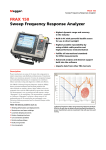
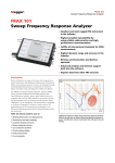
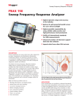
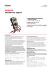
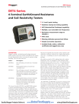
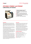
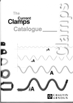
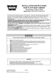
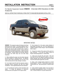
FRAX Series Sweep Frequency Response Analyzers FRAX Series Sweep Frequency Response Analyzers ■■Highest dynamic range and accuracy in the industry ■■Fulfills international standards for SFRA measurements ■■Advanced analysis and decision support built into the software ■■Imports data from other FRA test sets ■■Wireless ■■Battery communication (FRAX 101) operated (FRAX 99 and FRAX 101) Description Power transformers are some of the most vital components in today’s transmission and distribution infrastructure. Transformer failures cost enormous amounts of money in unexpected outages and unscheduled maintenance. It is important to avoid these failures and make testing and diagnostics reliable and efficient. The FRAX series of sweep frequency response analyzers (SFRA) detects mechanical and electrical changes of the core and winding assembly of power transformers. Major utilities and service companies have used the FRA method for more than a decade and the method is covered in international standards. The measurement is easy to perform and will capture a unique fingerprint of the transformer. The measurement result is compared to a reference fingerprint and gives a direct answer if the mechanical parts of the transformer are unchanged or not. Deviations indicate geometrical and/or electrical changes within the transformer. FRAX detects problems such as: Winding Shorted deformations and displacements turns and open windings Loosened Core clamping structures connection problems Partial winding collapse Faulty core grounds Core movements Collecting fingerprint data using Frequency Response Analysis (FRA) is an easy way to detect electro-mechanical problems in power transformers and an investment that will save time and money. FRAX Series Sweep Frequency Response Analyzers Application Analysis and software Power transformers are specified to withstand mechanical forces from both transportation and in-service events, such as faults and lightning. However, mechanical forces may exceed specified limits during severe incidents or when the insulation’s mechanical strength has weakened due to aging. A relatively quick test where the fingerprint response is compared to a post event response allows for a reliable decision on whether the transformer safely can be put back into service or if further diagnostics is required. As a general guideline, shorted turns, magnetization and other problems related to the core alter the shape of the curve in the lowest frequencies. Medium frequencies represent axial or radial movements in the windings and high frequencies indicate problems involving the cables from the windings to bushings and tap changers. Method basics A transformer consists of multiple capacitances, inductances and resistors, a very complex circuit that generates a unique fingerprint or signature when test signals are injected at discrete frequencies and responses are plotted as a curve. Capacitance is affected by the distance between conductors. Movements in the winding will consequently affect capacitances and change the shape of the curve. The SFRA method is based on comparisons between measured curves where variations are detected. One SFRA test consists of multiple sweeps and reveals if the transformer’s mechanical or electrical integrity has been jeopardized. An example of low, medium and high frequency response. The FRAX software provides numerous features for efficient data analysis. Unlimited tests can be open at the same time and the user has full control of which sweeps to compare. The response can be viewed in traditional magnitude vs. frequency and/or phase vs. frequency view. The user can also choose to present the data in an impedance or admittance vs. frequency view for powerful analysis on certain transformer types. Practical application In its standard application, a fingerprint / reference curve for each winding is captured when the transformer is new or when it is in a known good condition. These curves can later be used as reference during maintenance tests or when there is reason to suspect a problem. The most reliable method is the time-based comparison where curves are compared over time on measurements from the same transformer. Another method utilizes type-based comparisons between sister transformers with the same design. Lastly, a construction-based comparison can, under certain conditions, be used when comparing measurements between windings in the same transformer. These comparative tests can be performed 1) before and after transportation, 2) after severe through faults, 3) before and after overhaul and 4) as diagnostic test if you suspect potential problems. One SFRA test can detect winding problems that require multiple tests with different kinds of test equipment or problems that cannot be detected with other techniques at all. The SFRA test presents a quick and cost-effective way to assess if damages have occurred or if the transformer can safely be energized again. If there is a problem, the test result provides valuable information that can be used when determining further action. The figure above shows a single-phase transformer after a service overhaul where, by mistake, the core ground never got connected (red), and after the core ground was properly connected (green). This potential problem clearly showed up at frequencies between 1 kHz and 10 kHz and a noticeable change is also visible in the 10 kHz – 200 kHz range. Having a reference measurement on a mission critical transformer when an incident has occurred is, therefore, a valuable investment as it will allow for an easier and more reliable analysis. 2 FRAX Series Sweep Frequency Response Analyzers Benefits Features Smallest 1. Test object browser – Unlimited number of tests and sweeps. Full user control. and most rugged FRA instrument in the industry. Guaranteed repeatability by using superior cabling technology and standardized signal cable grounding technique (IEC 60076-18, Method 1). 2. Quick select tabs – Quickly change presentation view for different perspectives and analysis tools. 3. Quick graph buttons – Programmable graph setting lets you change views quickly and easily. Fulfills all international standards for Sweep Frequency Response Analysis (SFRA) measurements (IEC 60076-18, IEEE C57.149 etc). 4. Sweep/curve settings – Every sweep can be individually turned on or off, change color, thickness and position. Highest dynamic range and accuracy in the industry allowing even the most subtle electro-mechanical changes within the transformer to be detected. 5. Dynamic zoom – Zoom in and move your focus to any part of the curve. 6. Operation buttons – All essential functions at your fingertips; select with mouse, function keys or touch screen. Advanced analysis and support software tools allows for sound decision making with regard to further diagnostics analysis and/or transformer disposition. 7. Automated analysis compares two curves using an algorithm that compare amplitude as well as frequency shift and lets you know if the difference is severe, obvious or light. Built-in PC with powerful backlit screen for use in direct sunlight (FRAX 150). 1 2 4 3 5 6 Built-in-decision support is provided by using a built-in analysis tool based on the based on the SFRA standard DL/T 911-2004. 7 3 FRAX Series Sweep Frequency Response Analyzers Import and Export Considerations when performing SFRA measurements The FRAX software can import data files from other FRA instruments, making it possible to compare data obtained using another FRA unit. FRAX can import and export data according to the international XFRA standard format, as well as standard CSV and TXT formats. SFRA measurements are compared over time or between different test objects. This accentuates the need to perform the test with the highest repeatability and eliminates the influence from external parameters such as cables, connections and instrument performance. FRAX offers all the necessary tools to ensure that the measured curve represents the internal condition of the transformer. Optimized sweep setting The software offers the user an unmatched feature that allows for fast and efficient testing. Traditional SFRA systems use a logarithmic spacing of measurement points. This results in as many test points between 20 Hz and 200 Hz as between 200 kHz and 2 MHz and a relatively long measurement time. Good connections Bad connections can compromise the test results, which is why FRAX offers a rugged test clamp that ensures good connection to the bushings and solid connections to the instrument. The frequency response from the transformer contains a few resonances in the low frequency range, but a lot of resonances at higher frequencies. FRAX allows the user to specify less measurement points at lower frequencies and high measurement point density at higher frequencies. The result is a much faster sweep with greater detail where it is needed. Variable voltage The applied test voltage may affect the response at lower frequencies. Some FRA instruments do not use the 10 V peakto-peak used by major manufacturers and this may complicate comparisons between tests. FRAX standard voltage is 10 V peak-topeak, but FRAX also allows the user to adjust the applied voltage to match the voltage used in a different test. Contacts made with the C-clamp guarantee good connections. Shortest braid concept The connection from the cable shield to ground has to be the same for every measurement on a given transformer. Traditional ground connection techniques have issues when it comes to providing repeatable conditions. This causes unwanted variations in the measured response for the highest frequencies and makes analysis difficult. Dynamic range Making accurate measurements in a wide frequency range with high dynamics puts great demands on test equipment, test leads and test set up. FRAX is designed with these requirements in mind. It is rugged, able to filter induced interference and has the highest dynamic range and accuracy in the industry. FRAX dynamic range or noise floor is shown in red below with a normal transformer measurement in black. A wide dynamic range and low noise floor, allows for accurate measurements in every transformer. A margin of about 20 dB from the lowest response to the instruments noise floor should be maintained to obtain ±1 dB accuracy. The FRAX braid drops down from the connection clamp next to the insulating discs to the ground connection at the base of the bushing. This creates near identical conditions every time you connect to a bushing (regardless if it is tall or short) and is the recommended way of connecting in CIGRE TB342 and IEC 60076-18. Solid connections using the C-clamps and the shortest braid method to connect the shield to ground, makes it possible to eliminate connection problems and cable loops that otherwise affect the measurement. An example of a transformer measurement in comparison with the internal noise level in FRAX. 4 FRAX Series Sweep Frequency Response Analyzers FRAX 150 with Built-in PC Case and accessories FRAX 150 FRAX 101 FRAX 99 FRAX 150 has a built-in PC with a high contrast, powerful backlit screen suitable for work in direct sunlight. The cursor is controlled via the built-in joystick or using an external USB mouse, and the built-in keyboard makes data entry easy. Measurement section Test method Frequency range Frequency resolution Frequency inaccuracy Level resolution Number of points All data are stored on the built-in hard drive. The data can be moved to any other computer using a USB memory stick. Test button Built-in mouse with left and right click buttons (sealed to protect from dust and other contaminants) Measurement time Points spacing Sweep settings Navigation arrows Dynamic range (IEC 60076-18) Inaccuracy Enter key IF bandwidth PC Communication FRAX 150 FRAX 101 Close-up of FRAX 150 control panel Specifications FRAX 99/101/150 FRAX 99 Software Standards / guides Specifications are valid at nominal input voltage and an ambient temperature of +25°C, (77°F). Specifications are subject to change without notice. Environmental Application field The instrument is intended for use in medium and high-voltage substations and industrial environments. Ambient temperature Operating FRAX 150 FRAX 99/101 Storage Humidity CE-marking EMC LVD 1 0.20 – 24 V p-p (FRAX 101/150) 20 V p-p (FRAX 99) Measurement voltage 0.1 – 12 V p-p (FRAX 101/150) at 50 Ω 10 V p-p (FRAX 99) Output impedance 50 Ω Protection Short-circuit protected Frequency range 0.1 Hz – 25 MHz Sweep direction Low to high or high to low 2004/108/EC 2006/95/EC 11– 16 V DC 90 – 264 V AC, 47 – 63 Hz 24 Wh/2.2 Ah (FRAX99) 49 Wh/4.4 Ah (FRAX101) Analog Input Channels Sampling Frequency range Input impedance Sampling rate PC (FRAX 150) Operating system Memory 305 x 194 x 360 mm (12” x 7.6” x 14.2”) 250 x 169 x 52 mm (9.84” x 6.65” x 2.05”) – 520 x 460 x 220 mm (20.5” x 18.1” x 8.7”) 2 Simultaneously 0.1 Hz – 25 MHz 50 Ω 100 MS/s Windows® XP (embedded) 1000 records in internal memory External storage on USB stick PC Requirements (FRAX 99/101) Weight Instrument FRAX 150 FRAX 99/101 Internal USB (galvanically isolated) Wireless (Bluetooth)” and USB (galvanically isolated) USB (galvanically isolated) FRAX for Windows 2000/ XP/Vista/7/8 Fulfills requirements in Cigré Brochure 342, 2008. Mechanical condition assessment of transformer windings using FRA DL/T 911-2004, FRA on winding deformation of power transformers, IEC 60076 - 18 and IEEE PC57.149 as well as other standards and recommendations Channels Compliance voltage Dimensions Instrument FRAX 150 FRAX 99/101 Transport case FRAX 150 FRAX 99/101 Sweep frequency (SFRA) 0.1 Hz – 25 MHz, user selectable < 0.01% < 0.01% < 0.001 dB Default 1046, Up to 32 000 points, user selectable Default 64 s, fast setting, 37 s (20 Hz – 2 MHz) Log., linear or both Individual settings for customer defined frequency bands. Linear and logarithmic scale or combination of both >135 dB (FRAX101 and 150) >120 dB (FRAX99) ± 0.1 dB from +10 dB down to -50 dB ± 0.5 dB down to -100 dB (FRAX 101/150) ± 1 dB down to -100 dB (FRAX 99) User selectable, default <10% Analog Output -5°C to +50°C (23°F to +122°F) -20°C to +55°C (-4°F to +131°F) -20°C to 70°C (-4°F to +158°F) < 95% RH, non-condensing General DC power supply AC power supply Internal battery (optional) 16 kg (35 lbs) 15 kg (33 lbs) 12 kg (26 lbs) Operating system Processor Memory Hard drive Interface 6 kg (13 lbs) 1.4 kg (3.1 lbs) 1.8 kg (4 lbs) with battery 5 Note: PC not included Windows XP / Vista / 7 Pentium 500 MHz or higher 256 Mb RAM or more Minimum 30 Mb free Wireless / USB (FRAX 99/101) USB and Ethernet (FRAX 99) FRAX Series Sweep Frequency Response Analyzers Included accessories Ordering information Item Cat. No. FRAX-101 With accessories, 18 m (60 ft) cable set AC-19090 With accessories incl. battery, 18 m cable set AC-19091 With accessories, 9 m (30 ft) cable set AC-19092 With accessories incl. battery, 9 m cable set AC-19093 FRAX-99 With accessories, 9 m cable set AC-29090 With accessories, 18 m cable set AC-29092 With accessories, incl. battery, 9 m cable set AC-29095 Included accessories shown above: Mains cable, ground cable, (2) ground braid sets, (2) earth/ground braid leads (insulated), (2) Cclamps, generator cable, measure cable, field test box, nylon accessory pouch, (2) earth/ground braids with clamp, and canvas carrying bag for test leads. With accessories, incl. battery, 18 m cable set AC-29096 FRAX-150 With accessories, 18 m cable set AC-39090 With accessories, 9 m cable set AC-39092 FTB101 Included accessories for all models Generator cable Measure cable 4 x 3 m (10 ft) ground braid set 2 x 0.3 m (1 ft) braid with clamp 2 x C-clamp (bushing connector clamp) 2 x G-clamp (ground clamp) Field Test Box FTB101 Ground cable 5 m (15 ft) Mains cable Several international FRA guides recommend verification integrity of cable and instrument before and after a test using a test circuit with a known FRA response supplied by the equipment manufacturer. FRAX comes with a field test box FTB101 as a standard accessory and allows the user to perform this important validation in the field at any time and secure measurement quality. FRAX software for Windows User manual Additional included accessories for FRAX 99 AC/DC adapter Light transport case Canvas carrying bag (for accessories) USB cable Optional accessories Additional included accessories for FRAX 101 FDB101 AC/DC adapter Transport case Bluetooth adapter USB cable Additional included accessories for FRAX 150 Canvas carrying bag (for accessories) Optional Accessories The FRAX demo box FDB101 is a transformer kit that can be used for in-house training and demonstrations. The small transformer is a single-phase unit with capability to simulate normal as well as fault conditions. Open as well as shorted measurements can be performed. The unit also contains two test impedances, one of them the same as used in the FTB101 field test box. UK Archcliffe Road Dover CT17 9EN England T +44 (0) 1304 502101 F +44 (0) 1304 207342 [email protected] UNITED STATES 4271 Bronze Way Dallas TX 75237-1019 USA T 800 723 2861 (USA only) T +1 214 333 3201 F +1 214 331 7399 [email protected] Calibration set AC-90020 FRAX demo box FDB 101 AC-90050 FRAX generator and ref cable, 9 m (30 ft) GC-30040 FRAX generator and ref cable, 18 m (60 ft) GC-30042 FRAX measure cable, 9 m (30 ft) GC-30050 FRAX measure cable, 18 m (60 ft) GC-30052 C-clamps GC-80010 E-clamp (single hand grip clamp) GC-80030 OTHER TECHNICAL SALES OFFICES Valley Forge USA, College Station USA, Sydney AUSTRALIA, Danderyd SWEDEN, Ontario CANADA, Trappes FRANCE, Oberursel GERMANY, Aargau SWITZERLAND, Kingdom of BAHRAIN, Mumbai INDIA, Johannesburg SOUTH AFRICA, Chonburi THAILAND CERTIFICATION ISO Registered to ISO 9001 and 14001 FRAX-Series_DS_EN_NAFTAV03 www.megger.com Megger is a registered trademark