1
3-6
Chapter 3 - Programming EZPLC
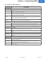
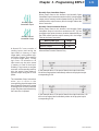
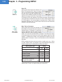
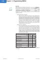
RLL Instructions Table (continued)
Instruction
Description
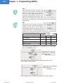
Compare Instructions
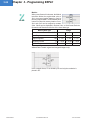
Equal To
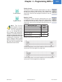
Allows power flow through this element if the data value of “Opr1” register is Equal to “Opr2” register
Not Equal To
Allows power flow through this element if the data value of “Opr1” register is NOT Equal to “Opr2” register
Greater Than
Allows power flow through this element if the data value of “Opr1” register is Greater Than “Opr2” register
Less Than
Allows power flow through this element if the data value of “Opr1” register is Less Than “Opr2” register
Greater Than or
Equal To
Allows power flow through this element if the data value of “Opr1” register is Greater Than or Equal to
“Opr2” register
Less Than or Equal
To
Allows power flow through this element if the data value of “Opr1” register is Less Than or Equal to “Opr2”
register
Limit
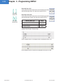
Allows power flow through this element if the data value of “Input” register is within the data values of “High
Limit” and “low Limit” registers
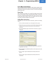
Math Instructions
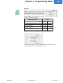
Add
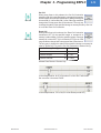
Adds two data values in “Opr1” and “Opr2” registers and stores the result in “Result” register
Subtract
Subtracts “Opr2” register data value from “Opr1” register data value and stores the result in “Result”
register
Multiply
Multiplies two data values in “Opr1” and “Opr2” registers and stores the result in “Result” register
Divide
Divides “Opr1” register data value by “Opr2” register data value and stores the result in “Result” register
Modulo
Divides “Opr1” register data value by “Opr2” register data value and stores only the remainder in “Result”
register
Absolute
Converts a negative data value from “Opr1” register to a positive value and stores it in “Result” register
Conversion
Copies the data value of “Opr” register, converts it into “Result” registers data type, and stores the data
value in “Result” register
Binary Conversion
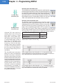
Converts the data value of “Source” register in Binary, BCD, or GRAY code to the data value of “Result”
register in Binary, BCD or GRAY Code
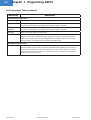
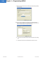
Bitwise Instruction
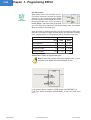
AND
Performs a bitwise AND operation between the data values of two registers “Opr1” and “Opr2”. The result
is stored in “Result” register
OR
Performs a bitwise OR operation between the data values of two registers “Opr1” and “Opr2”. The result is
stored in “Result” register
XOR
Performs a bitwise XOR operation between the data values of two registers “Opr1” and “Opr2”. The result
is stored in “Result” register
NOT
Performs a bitwise NOT operation on the data value of “Source” register and stores the result in
“Destination” register
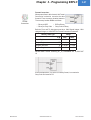
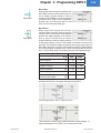
Shift Left
Performs a logical Shift Left on the data value of “Opr1” register by the data value of “Opr2” register and
stores the result in “Result” register
Shift Right
Performs a logical Shift Right on the data value of “Opr1” register by the data value of “Opr2” register and
stores the result in “Result” register
Rotate Left
Performs a logical Rotate Left on the data value of “Opr1” register by the data value of “Opr2” register and
stores the result in “Result” register
Rotate Right
Performs a logical Rotate Right on the data value of “Opr1” register by the value of “Opr2” register and
stores the result in “Result” register
EZAutomation
www.EZAutomation.net
1-877-774-EASY