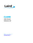
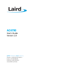
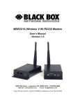
1
CL4790 USER GUIDE VERSION 3.0 Americas: +1-800-492-2320 Option 2 Europe: +44-1628-858-940 Hong Kong: +852-2923-0610 www.lairdtech.com/ramp CL4790 User Guide Version 2.0 FCC Notice WARNING: This device complies with Part 15 of the FCC Rules. Operation is subject to the following two conditions: (1) This device may not cause harmful interference and (2) This device must accept any interference received, including interference that may cause undesired operation. RF Exposure/Installation Instructions WARNING: To satisfy FCC RF exposure requirements for mobile transmitting devices, this equipment must be professionally installed such that the end user is prevented from replacing the antenna with a non-approved antenna. The end user should also be prevented from being within 20cm of the antenna during normal use with the exception of hands, feet, wrists and ankles. The preceding statement must be included as a CAUTION statement in manuals for OEM products to alert users on FCC RF Exposure compliance. Caution: Any change or modification not expressly approved by Laird could void the user’s authority to operate the equipment. Americas: +1-800-492-2320 Option 2 Europe: +44-1628-858-940 Hong Kong: +852-2923-0610 www.lairdtech.com/ramp 2 CONN-GUIDE_CL4790 CL4790 User Guide Version 2.0 REVISION HISTORY Version 1.0 1.1 2.0 Date 02 Aug 2013 3.0 18 Dec 2013 Changes Initial Release Changes and Revisions Major changes and revisions; updated format and data Separated Hardware Integration Guide (HIG) from User Guide information (created two separate documents). Add Related Documents section. Americas: +1-800-492-2320 Option 2 Europe: +44-1628-858-940 Hong Kong: +852-2923-0610 www.lairdtech.com/ramp 3 CONN-GUIDE_CL4790 CL4790 User Guide Version 2.0 CONTENTS Revision History ......................................................................................................................................... 3 Contents ..................................................................................................................................................... 4 CL4790 RF Transceiver ............................................................................................................................... 5 Overview ............................................................................................................................................................. 5 Features ............................................................................................................................................................... 5 Theory of Operation .................................................................................................................................. 6 RF Architecture .................................................................................................................................................... 6 Network Topologies ............................................................................................................................................. 6 Modes of Operation ............................................................................................................................................. 6 Security .............................................................................................................................................................. 11 Spread Spectrum History ............................................................................................................................... 11 How Spread Spectrum Works ........................................................................................................................ 11 Frequency Hopping Spread Spectrum............................................................................................................ 11 CL4790 Security Features .............................................................................................................................. 11 Programming the CL4790........................................................................................................................ 12 Appendix I: Troubleshooting .................................................................................................................. 14 Force 9600 Baud Recovery ................................................................................................................................. 14 Americas: +1-800-492-2320 Option 2 Europe: +44-1628-858-940 Hong Kong: +852-2923-0610 www.lairdtech.com/ramp 4 CONN-GUIDE_CL4790 CL4790 User Guide Version 2.0 CL4790 RF TRANSCEIVER The CL4790 transceiver is a Frequency Hopping Spread Spectrum (FHSS) radio designed for license-free operation in the 900 MHz Industrial, Scientific, and Medical (ISM) unlicensed band. The radio sustains a standard asynchronous serial data stream between two or more radios. Housed in a compact and rugged diecast enclosure, the radio is equipped to replace miles of serial cable with its wireless link. The radio features an RS232 or RS485 interface for integration into legacy data systems. Overview The CL4790 uses Frequency Hopping Spread Spectrum technology, where the units “hop” from frequency to frequency many times per second using a specific hop pattern applied to all the transceivers in the same network. A distinct hopping pattern is provided for each Channel Number, thereby allowing multiple networks to co-exist in the same area with limited interference. CL4790 transceivers operate in a Masterless architecture. When a CL4790 has data to transmit, it will enter transmit mode and start transmitting a sync pulse intended for an individual radio or broadcast to all transceivers within the same network and range. Intended receivers synchronize to this sync pulse, a session begins and data is transmitted. This instinctive dynamic peer-to-peer networking architecture enables several transceiver pairs to carry on simultaneous conversations on the same network. CL4790s implement a proprietary communication protocol to provide secure data transmissions. Using FHSS technology ensures data reliability over long distances. The CL4790 transceivers use the 900 MHz ISM license free frequency band, which requires no additional certifications when designing into a new or legacy data system. Each unit is small and easily portable for use in mobile and temporary settings as well as fixed installations. The CL4790 configuration software enables custom configurations based on unique application requirements. This document contains information about the hardware and software interface between a Laird CL7490 transceiver and an OEM host. Information includes the theory of operation, specifications, serial interface definition, security information and mechanical drawings. The OEM is responsible for ensuring the final product meets all appropriate regulatory agency requirements listed herein before selling any product. Note: CL4790 modules are referred to as the “radio” or “transceiver”. Individual naming differentiates product -specific features. The host (PC, Microcontroller or any connected device) is “OEM host.” Features Masterless: True peer-to-peer; each module can communicate with any other module within its range and network API commands to control packet routing and acknowledgement on a packet-by-packet basis Durable industrial grade enclosure Transparent operation; supports any legacy system Transmits around corners, through walls Reliable communication with serial UART speeds up to 115.2 Kbps Point-to-Point and Point-to-Multipoint setups Americas: +1-800-492-2320 Option 2 Europe: +44-1628-858-940 Hong Kong: +852-2923-0610 www.lairdtech.com/ramp 5 CONN-GUIDE_CL4790 CL4790 User Guide Version 2.0 THEORY OF OPERATION RF Architecture As opposed to a Server/Client protocol, a Masterless protocol does not require devices to be within range of a central synchronizing device (Server) to communicate. The communicating devices only need to be within range of each other. Communication between devices that are out of range of each other is also possible using repeaters or Host systems that can direct the data through a Daisy Chain type topology. Network Topologies Topology refers to the shape of a network, or the network's layout. The way different nodes in a network connect to each other and how they communicate is determined by the network's topology. The CL4790s have a Masterless communication protocol, referred to as Peer-to-Peer, which can be used to implement both Point-to-Point and Point-to-Multipoint topologies. See the AC4790 Embedded Module User Manual for more detailed information about setting up different topologies using the advanced API features in the 4790 family of radios. Modes of Operation The CL4790 has three different operating modes: Transmit Mode Receive Mode Command Mode If the transceiver is not communicating with another radio, it is in Receive mode actively listening for a sync pulse from another transceiver. If the transceiver determines that it hears a sync pulse that is addressed to itself or broadcast on its network, it responds by going into session with the radio that sent the pulse. The LINK LED on the CL4790 illuminates to show that it is In Session. A transceiver enters Transmit or Command mode when the OEM host sends data over the serial interface. The contents of the data on the serial interface determine which of two modes the radio enters. Transmit Mode All packets sent over the RF are either Addressed or Broadcast packets. You may dynamically control Broadcast and Addressed delivery with the API Control byte, which can be modified during operation with On-the-Fly commands (for more information on APIs and on-the-fly commands, see the AC4790 Embedded Module User Manual. To prohibit transceivers from receiving broadcast packets, Unicast only can be enabled. When a radio has data to transmit, it sends out a sync pulse to initiate a session with one or more radios. This 25 ms sync pulse is sent during the first half of each 50 ms hop and transparent to the OEM Host. Once a Session has been established, the radio transmits the data during the remaining 25 ms of the current hop. The radio will stay in transmit mode until its Session Count expires. When sending addressed packets, Session Count is defined as Session Count Refresh (EEPROM address 0xC4) + number of transmit retries (EEPROM address 0x4C). When sending broadcast packets, Session Count is equal to Session Count Refresh (EEPROM address 0xC4) + number of broadcast attempts (EEPROM address 0x4D). Once the radio exits the Session it returns to the default Receive Mode. Addressed Packets When sending an addressed packet, the RF packet sends only to the receiver specified in the Destination Address. To increase the odds of successful delivery, Transmit Retries are utilized. Transparent to the OEM host, the sending radio sends the RF packet to the intended receiver. If the receiver receives the packet free of errors, it returns an RF acknowledge within the same 50 ms hop. If a receive acknowledgement is not received, the radio uses a transmit retry to resend the packet. The radio continues CONN-GUIDE_CL4790 Americas: +1-800-492-2320 Option 2 6 Europe: +44-1628-858-940 Hong Kong: +852-2923-0610 www.lairdtech.com/ramp CL4790 User Guide Version 2.0 sending the packets until either (1) it receives an acknowledgement, or (2) it has used all transmit retries. The received packet only sends to the OEM host if and when it is received free of errors. Note: If Transmit Retries is set to 1 the radio will only attempt to send the data one time with no retries, the minimum setting for Transmit Retries is 1 and cannot be set to 0. Broadcast Packets When sending a broadcast packet, the RF packet sends out to every eligible transceiver on the network. To increase the odds of successful delivery, Broadcast Attempts are utilized. Transparent to the OEM host, the sending radio sends the RF packet to the intended receiver(s). Unlike Transmit Retries, all Broadcast Attempts are used regardless of when the RF packet is actually received and without RF acknowledgements. If the packet is received on the first attempt, the receiver ignores the remaining broadcast attempts. The received packet is only sent to the OEM host if and when it is received free of errors. Note: Like Transmit Retries, if Broadcast Attempts is set to 1 the transceiver will send the data one time with no additional attempts. Receive Mode If a transceiver detects a sync pulse, addressed to itself or broadcast on its network, while in Receive Mode, it will join the Session and begin receiving data. While in Receive Mode, subsequent data of up to 128 bytes can be received every hop (50 ms). When a transceiver is in Session, its Session Count is decremented by one every hop. When the Session Count reaches zero, the transceiver exits the Session. In order to continue receiving data, the transceivers update their Session Count every time data or an RF acknowledge is received. The SLock0 and SLock1 settings control Session Count as shown below. Table 1: Session Count Truth Table Case Slock0 Slock1 Transceiver Receiving an Addressed Packet Transceiver Receiving a Broadcast Packet 1 0 0 2 0 1 3* 1 0 4 1 1 Radio loads its Current Session Count with its Session Count Refresh Radio loads its Current Session Count with (its Transmit Retries + its Session Count Refresh) Radio loads its Current Session Count with the remote radio’s Session Count Refresh Radio loads its Current Session Count with the remote radio’s Current Session Count Radio loads its Current Session Count with its Session Count Refresh Radio loads its Current Session Count with (its broadcast attempts + its Session Count Refresh) Radio loads its Current Session Count with the remote radio’s Session Count Refresh Radio loads its Current Session Count with the remote radio’s Current Session Count * EEPROM Default. This may not be the best setting for all applications. If having issues use Case 4. Note 1: For Broadcast/Addressed packets, the Session Count for Full Duplex is 2x the value of Session Count in Half Duplex. Note 2: It is best to have all transceivers with the same Session Count Refresh (EEPROM Address 0xC4) value. Session Count Refresh must not be set to 0x00. Case 1 In this case, a radio loads its Session Count with its Session Count Refresh. This is suitable for Half Duplex communication where immediate response is not expected from the remote radio. Note: The term “immediate response” refers to the application layer and not the RF acknowledgment. Case 2 In this case, a radio loads its Session Count with (its Session Count Refresh + its Transmit Retries). This case is suitable for applications where there are high levels of interference and it is likely that transmit retries will be necessary to maintain reliable communications. Americas: +1-800-492-2320 Option 2 Europe: +44-1628-858-940 Hong Kong: +852-2923-0610 www.lairdtech.com/ramp 7 CONN-GUIDE_CL4790 CL4790 User Guide Version 2.0 When an addressed packet or a response to a broadcast packet is sent, the sending radio will listen for a successful acknowledgement. If an acknowledgement is not sent, the radio will resend the packet until either an acknowledgement is received or it has exhausted all available transmit retries. If two radios are on the last hop of the current session and a retry is required, it is possible that once the current session has ended the receiving radio could go into session with a different radio and miss the final packet of the previous session. Adding the radios Transmit retries to its Current Session Count will ensure that the radio does not exit the session when the remote radio is using a Transmit Retry. Case 3 In this case a radio loads its Session Count with the remote radio's Session Count Refresh. This is suitable for full duplex applications as the Session is extended as long as there is communication. Note: This is the default case with which the radio ships and may not work well for all applications. Use Case 4 when a large number of data packets are lost during operation. Case 4 In this case, a radio loads its Session Count with the remote radio's current Session Count. This is suitable for daisy chain applications and large networks in which radios cannot stay in session longer than needed. This case guarantees that two radios will stay in session as long as they have data to communicate and will both leave the session at the same time. Command Mode A radio enters Command mode when data is received over the serial interface from the OEM host and contains the “AT+++” (Enter AT Command mode) command. Once in Command mode, all data received by the radio is interpreted as command data. Command Data may exist as either EEPROM Configuration or OnThe-Fly commands. For more information on EEPROM Configuration and On-the-Fly commands, download the AC4790 Embedded Module User Manual). Americas: +1-800-492-2320 Option 2 Europe: +44-1628-858-940 Hong Kong: +852-2923-0610 www.lairdtech.com/ramp 8 CONN-GUIDE_CL4790 CL4790 User Guide Version 2.0 Figure 1: Pending RF data in buffer flow Americas: +1-800-492-2320 Option 2 Europe: +44-1628-858-940 Hong Kong: +852-2923-0610 www.lairdtech.com/ramp 9 CONN-GUIDE_CL4790 CL4790 User Guide Version 2.0 Figure 2: Pending RF data in buffer flow Americas: +1-800-492-2320 Option 2 Europe: +44-1628-858-940 Hong Kong: +852-2923-0610 www.lairdtech.com/ramp 10 CONN-GUIDE_CL4790 CL4790 User Guide Version 2.0 Security The 4790 product family utilizes a Frequency Hopping Spread Spectrum (FHSS) technology, which provides the foundation for secure digital wireless communications. The purpose of this section is to take a brief look at how spread spectrum technology works and explain how an OEM enables specific security features available in the CL4790. Spread Spectrum History Spread Spectrum, or SS, dates back to World War II, when actress Hedy Lamarr and composer George Antheil were granted a U.S. patent on a simple frequency hopping continuous wave (CW) system. These early research and development efforts tried to provide countermeasures for radar, navigation beacons, and communications. How Spread Spectrum Works SS radio communication has long been a favourite technology of the military because it resists jamming and is hard for an enemy to intercept. And now, this very same technology is widely used in the commercial, industrial and even consumer markets. The reason: SS signals distribute over a wide range of frequencies and then collect onto their original frequency at the receiver, making them so inconspicuous they are almost transparent. Just as they difficult to intercept by a military opponent, so are they unlikely to interfere with other signals intended for business and consumer users – even ones transmitted on the same frequencies. Spread signals are intentionally made to have a much wider band than the information they are carrying and use special pseudo noise codes to make them more noise-like. It is this very characteristic that makes SS signals difficult to detect, intercept, and demodulate. SS signals are hard to detect on narrowband equipment because the signal's energy spreads over a much wider bandwidth. Further, SS signals are harder to jam (interfere with) than narrowband signals and have a much lower probability of being intercepted, which is why the military has used SS for so many years. The spread of energy over a wide band makes SS signals less likely to interfere with narrowband communications. Narrowband communications, conversely, cause little to no interference to SS systems because the receiver effectively integrates the signal over a wide bandwidth to recover it. Besides being hard to intercept and jam, spread spectrum signals are also difficult to exploit or imitate. Signal exploitation is the ability of a non-network member to listen to a network and use information from the network without being a valid network member or participant. Imitation is the act of falsely or maliciously introducing false traffic or messages into a network. SS signals also are naturally more secure than narrowband radio communications. Thus SS signals can have any degree of message privacy that is desired. Messages can also be encrypted to any level of secrecy desired. The very nature of SS allows military or intelligence levels of privacy and security with minimal complexity. While these characteristics may not be very important to everyday business or consumer needs, these features are important to understand. Frequency Hopping Spread Spectrum An FHSS radio does just what its name implies – that is, it “hops” from frequency to frequency over a wide band. The specific order in which it occupies frequencies is a function of a code sequence, and the rate of hopping from one frequency to another is a function of the information rate. CL4790 Security Features In addition to FHSS technology, Laird has implemented three levels of security in the CL4790. All three levels associate with their own EEPROM parameter that you may program for permanent operation or change during system operation in volatile memory using On-the-Fly commands (download the AC4790 Embedded Module User Manual). The first two levels of security configure and establish a network of transceivers and are defined as the RF Channel Number and System ID. Americas: +1-800-492-2320 Option 2 Europe: +44-1628-858-940 Hong Kong: +852-2923-0610 www.lairdtech.com/ramp 11 CONN-GUIDE_CL4790 CL4790 User Guide Version 2.0 The RF Channel Number represents a specific hopping sequence and provides physical separation between collocated networks. Thus, all transceivers in a network must use the same RF Channel Number. There are a total of 56 Channel Numbers. Note: RF Channels 16-47 are restricted to US/Canada, RF Channels 48-55 restrict operation to 915-928 MHz and are normally only used in Australia. System ID is similar to a password character or network number and makes network eavesdropping more difficult. A receiving radio will not go in session (communicate) with another radio on a different System ID. There are a total of 256 System ID values. In FHSS technology, RF Channel Number and System ID are still not enough to secure your data. The CL4790 supports the Data Encryption Standard (DES), which is the third level of security. Encryption is the process of encoding an information bit stream to secure the data content. The algorithm described in this standard specifies both encrypting and decrypting operations which are based on a binary number called a key. A key of 56 bits encrypts and decrypts the data. The encryption algorithm specified in this standard is commonly known among those using the standard. The unique key chosen for particular application makes the results of encrypting data using the algorithm unique. Selection of a different key causes the encrypted data that is produced for any given set of inputs to differ. The cryptographic security of the data depends on the security provided for the key which encrypts and decrypts the data. Recover data from the encryption by using exactly the same key which encrypts it. Unauthorized recipients of the encrypted data who know the algorithm but do not have the correct key cannot derive the original data algorithmically. However, anyone who does have the key and algorithm can easily decrypt the encrypted data and obtain the original data. A standard algorithm based on a secure key thus provides a basis for exchanging encrypted data by issuing the encryption key to those authorized to have the data. PROGRAMMING THE CL4790 Laird provides the easy-to-use CL4790 Configuration Utility software for programming the CL4790. The GUI based software does not require any hardware configuration and works by itself. The software is compatible with Microsoft® Windows. CL4790s are plug-and-play devices that work with minimal or no configuration. This section provides instructions for quick and simple setup of CL4790 networks. The Laird Configuration Utility User Manual provides a full description of the software tool’s functionality and features. CL4790 customers who need advanced features and functionality like Transmit/Receive API can unlock these and other features in the Laird Configuration Utility software using the Enabling the Security Pane application note. The Info Center located on the Configure tab of the Laird Configuration Utility provides a quick explanation of all CL4790 features. Detailed descriptions for all available 4790 features are found in the AC4790 Embedded Module User Manual. To program the CL4790, follow these steps: 1. 2. 3. 4. 5. 6. 7. 8. Start the Laird Configuration Utility. Click here to download. Connect a CL4790 unit to the serial port on the PC (refer to the Serial Interface section). Attach the antenna to the CL4790 unit; make sure the connection is secure. Connect the power supply to the CL4790 unit. Make sure the Pwr LED is on. In the PC Settings tab in the Configuration Utility, select Connex4790 from the Product drop-down. Click Find Port. From the Port drop-down menu, select the COM port that is connected to the CL4790. Select the Baud Rate from the drop-down menu. Americas: +1-800-492-2320 Option 2 Europe: +44-1628-858-940 Hong Kong: +852-2923-0610 www.lairdtech.com/ramp 12 CONN-GUIDE_CL4790 CL4790 User Guide Version 2.0 Note: 9. All CL4790 units ship with a default baud rate of 57600 (unless units have been pre-configured to match specific serial settings). If the Interface Baud Rate of the CL4790 unit is changed, the PC Setting baud rate must match the device baud rate to allow proper programming of the units. Click Open Port and verify that the Port (1/2) status bar at the bottom of the window shows the correct COM number, is OPEN, and CTS is Low. Note: If connecting a CL4790-RS485 unit, set Port (1/2) Handshaking to NONE and disregard the status of CTS. Refer to the Serial Interface section for more information. 10. Go to the Configure tab and click Read Radio. 11. Change settings based on the type of network needed. Note: The Laird Configuration Utility automatically programs the mode (point-to-point or point-tomultipoint) based on the radio’s current settings: If the Destination Address field is set to any value other than FF FF FF FF FF FF, the radio sends data only to the radio whose MAC matches that specified in the Destination Address field (pointto-point). If the Destination Address field is set to FF FF FF FF FF FF, it is set to Broadcast mode and transmits to all transceivers in range with the same System ID and RF Channel (point-tomultipoint). For more information on settings, see the Info Center in the Laird Configuration Utility or the AC4790 Embedded Module User Manual. Note: The Show Defaults button can display sample Radio Settings. These settings may not reflect the current default settings of the radio. 12. After all changes are made, click Write Radio to save the changes. RELATED DOCUMENTS AND FILES The following additional CL4790 technical documents are also available from the Laird RAMP ConnexLink modules product page under the Documentation tab: Product Brief CL4790 Hardware Integration Guide The following downloads are also available from the Laird RAMP ISM modules product page: Configuration Utility USB Drivers Americas: +1-800-492-2320 Option 2 Europe: +44-1628-858-940 Hong Kong: +852-2923-0610 www.lairdtech.com/ramp 13 CONN-GUIDE_CL4790 CL4790 User Guide Version 2.0 APPENDIX I: TROUBLESHOOTING Problem Read Radio displays error message: “Radio not responding.” Write Radio displays error: “Radio not responding.” Garbled Data received. Client’s Link LED does not come on. Link LED is on, but data does not get transmitted or received. Solution Make sure the PC Settings are right. Make sure the CL4790 unit uses the right serial cable. Refer to Error! Reference source not found.. If any other program using the same COM port as CL4790 is open, close that program and try to read the radio again. Reset the radio by cycling power after each unsuccessful read. Cycle power to the radio. Read the radio, make changes and click Write Radio. Check Data Encryption Standard settings. Make sure the unit is connected to power. Cycle power to the radio. Make sure the CL4790 unit or units connect to the correct COM port. Check the COM port settings for correct baud rate, parity, and either Hardware or No Flow Control. May be caused by Flow Control set to Xon/Xoff. Try increasing the Maximum Transmit Attempts (clients) and/or Broadcast Attempts (servers) in small increments until communication is established. Connect a Null Modem adapter between the client and its host device. Check the Destination Address setting. If these tips do not resolve the problem, please call our toll free number at (800) 492-2320, option 2 for technical support. Hours are Monday through Friday, 8:00 am to 5:00 pm Central Standard Time. Force 9600 Baud Recovery To force the serial interface to a known value, perform the following steps (this also sets the RF Packet Size and Interface Timeout to default values): 1. 2. 3. Remove power from the radio. Remove the screws on the case and slide the radio out. Set a jumper (a wire or even a pair of tweezers work because it is a low voltage line) between the pins indicated in Figure 3. Figure 3: CL4790 with jumper pins highlighted 4. Connect the radio to the PC via a straight through cable. 5. Power on the radio. 6. On the PC Settings tab, click Find Ports. Americas: +1-800-492-2320 Option 2 14 Europe: +44-1628-858-940 Hong Kong: +852-2923-0610 www.lairdtech.com/ramp CONN-GUIDE_CL4790 CL4790 User Guide Version 2.0 7. 8. Select the appropriate port from the drop-down list. Set the rest of the settings to: 9. 10. 11. 12. 13. 14. 15. 16. 17. Baud Rate: 9600 Parity: None Handshaking: Hardware Data Bits: 8 Stop Bits: 1 Under Options, ensure the Read/Write with AT Commands check box is selected. Ensure the Port Status is open. On the Configure tab, click Read Radio. Set the Interface Baud Rate to the appropriate value and click Write Radio. Power off the radio. Remove the jumper. Power on the radio. Set the Baud Rate on the PC Settings tab to the baud rate you configured on the radio. On the Configure tab, click Read Radio. Americas: +1-800-492-2320 Option 2 Europe: +44-1628-858-940 Hong Kong: +852-2923-0610 www.lairdtech.com/ramp 15 CONN-GUIDE_CL4790