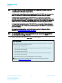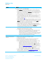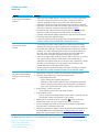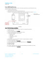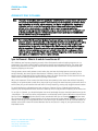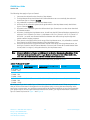
1
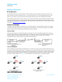
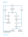
CL4490 USER GUIDE VERSION 3.0 [email protected] www.lairdtech.com/ramp CL4490 User Guide Version 3.0 FCC Notice WARNING: This device complies with Part 15 of the FCC Rules. Operation is subject to the following two conditions: (1) This device may not cause harmful interference and (2) This device must accept any interference received, including interference that may cause undesired operation. RF Exposure/Installation Instructions WARNING: To satisfy FCC RF exposure requirements for mobile transmitting devices, this equipment must be professionally installed such that the end user is prevented from replacing the antenna with a non-approved antenna. The end user should also be prevented from being within 20cm of the antenna during normal use with the exception of hands, feet, wrists and ankles. The preceding statement must be included as a CAUTION statement in manuals for OEM products to alert users on FCC RF Exposure compliance. Caution: Any change or modification not expressly approved by Laird could void the user’s authority to operate the equipment. Americas: +1-800-492-2320 Option 2 Europe: +44-1628-858-940 Hong Kong: +852-2923-0610 www.lairdtech.com/ramp 2 Laird Technologies CL4490 User Guide Version 3.0 REVISION HISTORY Version Date Version 1.0 Changes Initial Release Version 1.1 Oct. 2012 Major changes and revisions throughout document Version 2.0 5 April 2013 Major changes and revisions; updated format and data Version 3.0 10 December 2013 Separated from Hardware Integration Guide Americas: +1-800-492-2320 Option 2 Europe: +44-1628-858-940 Hong Kong: +852-2923-0610 www.lairdtech.com/ramp 3 Laird Technologies CL4490 User Guide Version 3.0 CONTENTS CL4490 RF Transceiver ................................................................................................................................. 5 Overview .................................................................................................................................................... 5 Features ..................................................................................................................................................... 5 Status LEDs ................................................................................................................................................... 6 CL4490 ...................................................................................................................................................... 6 CL4490-PRO .............................................................................................................................................. 6 Theory of Operation .................................................................................................................................... 7 RF Architecture........................................................................................................................................... 7 Network Topologies ................................................................................................................................... 7 Modes of Operation ................................................................................................................................... 8 Security .................................................................................................................................................... 11 Programming the CL4490 .......................................................................................................................... 13 Appendix I: Troubleshooting .................................................................................................................... 15 Force 9600 Baud Recovery ....................................................................................................................... 18 Appendix II: Sync to Channel .................................................................................................................... 19 Sync to Channel - What is it and do I need to use it? ............................................................................... 19 How do I configure Sync to Channel? ...................................................................................................... 22 I’ve configured my radios, what’s next? ................................................................................................... 29 Related Documents and Files .................................................................................................................... 32 Americas: +1-800-492-2320 Option 2 Europe: +44-1628-858-940 Hong Kong: +852-2923-0610 www.lairdtech.com/ramp 4 Laird Technologies CL4490 User Guide Version 3.0 CL4490 RF TRANSCEIVER The CL4490 transceiver is a Frequency Hopping Spread Spectrum (FHSS) radio designed for license-free operation in the 900 MHz Industrial, Scientific, and Medical (ISM) unlicensed band. The radio sustains a standard asynchronous serial data stream between two or more radios out of the box. Housed in a compact and rugged die-cast enclosure, the radio is equipped to replace miles of serial cable using a CL4490 RS232, RS485, or USB interface. This guide is for the CL4490 and CL4490-PRO. References to the CL4490 apply to the CL4490-PRO, unless otherwise specified. Overview The CL4490 uses Frequency Hopping Spread Spectrum technology, where the units "hop" from frequency to frequency many times per second using a specific hop pattern applied to all the transceivers in the same network. A distinct hopping pattern is provided for each channel number, thereby allowing multiple networks to coexist in the same area with limited interference. CL4490 transceivers operate in a Point-to-Point or Point-to-Multipoint, client-server architecture. One transceiver is configured as a server and there can be one or many clients. To establish communication between transceivers, the server emits a beacon and upon detecting a beacon, a Radio Frequency (RF) link is established with the client(s). CL4490s implement a proprietary communication protocol to provide secure data transmissions. Using FHSS technology ensures data reliability over long distances. The license-free frequency bands ensure that the units are ready for use with no further certification requirements. Each unit is small and easily portable for use in mobile and temporary settings as well as fixed installations. The CL4490 configuration software enables custom configurations based on unique application requirements. This document contains information about the hardware and software interface between a Laird CL4490 transceiver and an OEM host. Information includes the theory of operation, specifications, serial interface definition, security information and mechanical drawings. The OEM is responsible for ensuring before the final product is sold that it meets all appropriate regulatory agency requirements listed herein. Additionally, this document contains a list of Related Documents and Files. Note: CL4490 modules are referred to as the “radio” or “transceiver”. Individual naming is used to differentiate product-specific features. The host (PC, Microcontroller, or any device connected to the CL4490) is referred to as “OEM host”. Features Networking and Security Easy to Use Retries and Acknowledgements API Commands to control packet routing and Continuous 76.8kbps RF data stream Software selectable interface baud rates from acknowledgement on a packet-by-packet basis 1200bps to 115.2kbps Frequency Hopping Spread Spectrum for security Advanced configuration available using AT and interference rejection commands Customizable RF Channel number and System ID Dynamic link analysis, remote radio discovery Low latency and high throughput Americas: +1-800-492-2320 Option 2 Europe: +44-1628-858-940 Hong Kong: +852-2923-0610 www.lairdtech.com/ramp 5 Laird Technologies CL4490 User Guide Version 3.0 STATUS LEDS CL4490 Figure 1: CL4490 Status LEDs Table 1 describes each of the CL4490 Status LEDs. Table 1: CL4490 Status LEDs LED Color Description Pwr Link Green Red Rx Tx Green Red On. Indicates the unit is powered up. On. Indicates the client unit(s) and server unit are in transmitting range of each other. Note: A client’s Link LED lights when in range of the server. It is always lit on a server. When flashing, indicates the CL4490 is receiving data. When flashing, indicates the CL4490 is transmitting data. CL4490-PRO Figure 2: CL4490-PRO Status LEDs Note: DIP Switches only appear on the CL4490-PRO. Table 2 describes each of the CL4490 Status LEDs. Table 2: CL4490-PRO status LEDs LED Color Description Pwr Link Green Red RXD TXD Green Red Device is powered up. The client unit(s) and server unit are in range of each other. Note: A client’s Link LED lights when in range of the server. It is always lit on a server. When flashing, the CL4490-PRO is receiving data. When flashing, the CL4490-PRO is transmitting data. Americas: +1-800-492-2320 Option 2 Europe: +44-1628-858-940 Hong Kong: +852-2923-0610 www.lairdtech.com/ramp 6 Laird Technologies CL4490 User Guide Version 3.0 THEORY OF OPERATION RF Architecture The CL4490 utilizes a server-client network where all clients synchronize their hopping to the server. The server transmits a beacon during the first 1 ms of every hop (20 ms). The client transceivers listen for this beacon; upon hearing it, they synchronize their hopping with the server and the LINK LED illuminates. Each network should consist of only one server. Two servers should never use the same RF Channel number in the same coverage area – the cross-talk between the two servers severely hinders RF communications. For those applications requiring collocated servers, Laird recommends using the Sync to Channel feature, further explained in Appendix II: Sync to Channel. Network Topologies Topology refers to the shape of a network, or the network's layout. The way different nodes in a network connect to each other and how they communicate is determined by the network's topology. The CL4490s support a Point-to-Point and a Point-to-Multipoint network topology. Point-to-Point A Point-to-Point system is a simple arrangement consisting of just two CL4490s programmed to the same System ID and RF Channel (a single server/client pair). Sometimes referred to as a wireless bridge, a Point-toPoint link replaces a single communications cable. You might use a Point-to-Point link to connect a programmable logic controller (PLC) to a remote monitoring station. Point-to-Multipoint Point-to-Multipoint systems have one base station, or access point, that controls communications with all of the other wireless nodes in the network. This allows you to create a wireless network with multiple nodes. By programming each CL4490 with a network-specific Channel Number and System ID, multiple networks can coexist. You may configure collocated systems by programming each system with a network specific System ID and RF Channel Number. See Figure 3 for an example of collocated point-to-multipoint systems. Figure 3: Point-to-multipoint systems Americas: +1-800-492-2320 Option 2 Europe: +44-1628-858-940 Hong Kong: +852-2923-0610 www.lairdtech.com/ramp 7 Laird Technologies CL4490 User Guide Version 3.0 Modes of Operation The CL4490 has three different operating modes: Transmit Mode Receive Mode Command Mode If the transceiver is not communicating with another radio, it is in Receive mode actively listening for a beacon from the server. If the client determines that the beacon is from a server operating on the same RF Channel and System ID, it synchronizes its hopping sequence to the server and illuminates the LINK LED. A transceiver enters Transmit or Command mode when the OEM host sends data over the serial interface. Transmit Mode All packets sent over the RF are either Addressed or Broadcast packets. You may dynamically control Broadcast and Addressed delivery with the API Control byte, which can be modified during operation with On-the-Fly commands (for more information on APIs and On-the-Fly commands, download the AC4490 Embedded Module User Manual). Addressed Packets When sending an addressed packet, the RF packet sends only to the receiver specified in the destination address. To increase the odds of successful delivery, Transmit Retries are utilized. Transparent to the OEM host, the sending radio sends the RF packet to the intended receiver. If the receiver receives the packet free of errors, it returns an RF acknowledge within the same 20 ms hop. If a receive acknowledgement is not received, the radio uses a transmit retry to resend the packet. The radio continues sending the packets until either (1) it receives an acknowledgement, or (2) it has used all transmit retries. The received packet only sends to the OEM host if and when it is received free of errors. Broadcast Packets When sending a broadcast packet, the RF packet sends out to every eligible transceiver on the network. To increase the odds of successful delivery, Broadcast attempts are utilized. Transparent to the OEM host, the sending radio sends the RF packet to the intended receiver(s). Unlike Transmit Retries, all broadcast attempts are used regardless of when the RF packet actually receives and without RF acknowledgements. If the packet is received on the first attempt, the receiver ignores the remaining broadcast attempts. The received packet is only sent to the OEM host if and when it is received free of errors. Receive Mode When a transceiver is not in Transmit or Command mode, it is in Receive mode listening for data. While in Receive mode, the radio may receive subsequent data of up to 80 bytes every hop (20 ms). To prohibit transceivers from receiving broadcast packets, enable Unicast only. Command Mode A radio enters Command mode when data is received over the serial interface from the OEM host and contains the “AT+++” (Enter AT Command mode) command. Once in Command mode, all data received by the radio interprets as command data. Command Data may exist as either EEPROM Configuration or On-theFly commands. For more information on On-the-Fly commands, download the AC4490 Embedded Module User Manual. Americas: +1-800-492-2320 Option 2 Europe: +44-1628-858-940 Hong Kong: +852-2923-0610 www.lairdtech.com/ramp 8 Laird Technologies CL4490 User Guide Version 3.0 Figure 4: Pending RF data in buffer flow Americas: +1-800-492-2320 Option 2 Europe: +44-1628-858-940 Hong Kong: +852-2923-0610 www.lairdtech.com/ramp 9 Laird Technologies CL4490 User Guide Version 3.0 Figure 5: Pending RF data in buffer flow Americas: +1-800-492-2320 Option 2 Europe: +44-1628-858-940 Hong Kong: +852-2923-0610 www.lairdtech.com/ramp 10 Laird Technologies CL4490 User Guide Version 3.0 Security The 4490 product family utilizes a Frequency Hopping Spread Spectrum (FHSS) technology, which provides the foundation for secure digital wireless communications. The purpose of this section is to take a brief look at how spread spectrum technology works and explain how an OEM enables specific security features available in the CL4490. Spread Spectrum History Spread Spectrum, or SS, dates back to World War II, when Austro-American actress Hedy Lamarr and American composer, George Antheil, were granted a patent on a simple frequency hopping continuous wave (CW) system. These early research and development efforts tried to provide countermeasures for radar, navigation beacons, and communications. How Spread Spectrum Works SS radio communication has long been a favorite technology of the military because it resists jamming and is hard for an enemy to intercept. And now, this very same technology is widely used in the commercial, industrial and even consumer markets. The reason: SS signals distribute over a wide range of frequencies and then collect onto their original frequency at the receiver, making them so inconspicuous they are almost transparent. Just as they are difficult to intercept by a military opponent, so are they unlikely to interfere with other signals intended for business and consumer users – even ones transmitted on the same frequencies. Spread signals are intentionally made to have a much wider band than the information they are carrying and use special pseudo noise codes to make them more noise-like. It is this very characteristic that makes SS signals difficult to detect, intercept, and demodulate. SS signals are hard to detect on narrowband equipment because the signal's energy spreads over a much wider bandwidth. Further, SS signals are harder to jam (interfere with) than narrowband signals and have a much lower probability of being intercepted, which is why militaries have used SS for so many years. The spread of energy over a wide band makes SS signals less likely to interfere with narrowband communications. Narrowband communications, conversely, cause little to no interference to SS systems because the receiver effectively integrates the signal over a wide bandwidth to recover it. Besides being hard to intercept and jam, spread spectrum signals are also difficult to exploit or imitate. Signal exploitation is the ability of a non-network member to listen to a network and use information from the network without being a valid network member or participant. Imitation is the act of falsely or maliciously introducing false traffic or messages into a network. SS signals also are naturally more secure than narrowband radio communications. Thus SS signals can have any degree of message privacy that is desired. Messages can also be encrypted to any level of secrecy desired. The very nature of SS allows military or intelligence levels of privacy and security with minimal complexity. While these characteristics may not be very important to everyday business or consumer needs, these features are important to understand. Frequency Hopping Spread Spectrum An FHSS radio does just what its name implies – that is, it “hops” from frequency to frequency over a wide band. The specific order in which it occupies frequencies is a function of a code sequence, and the rate of hopping from one frequency to another is a function of the information rate. Americas: +1-800-492-2320 Option 2 Europe: +44-1628-858-940 Hong Kong: +852-2923-0610 www.lairdtech.com/ramp 11 Laird Technologies CL4490 User Guide Version 3.0 CL4490 Security Features In addition to FHSS technology, Laird has implemented three levels of security in the CL4490. All three levels associate with their own EEPROM parameter that you may program for permanent operation or change during system operation in volatile memory using on-the-fly commands (download the AC4490 Embedded Module User Manual for more information). The first two levels of security must configure and establish a network of transceivers and are defined as the RF Channel Number and System ID. The RF Channel Number represents a specific hopping sequence and provides physical separation between collocated networks. Thus, all transceivers in a network must use the same RF Channel Number. There are a total of 56 Channel Numbers. Note: RF Channels 0-47 are restricted to US/Canada, RF Channels 48-55 restrict operation to 915-928 MHz and are normally only used in Australia. System ID is similar to a password character or network number and makes network eavesdropping more difficult. A receiving radio will not go in range of or communicate with another radio on a different System ID. There are a total of 256 System ID values. If FHSS technology, Channel Number and System ID are still not enough to secure your data, the CL4490 also supports the Data Encryption Standard (DES), which is the third level of security. Encryption is the process of encoding an information bit stream to secure the data content. The algorithm described in this standard specifies both encrypting and decrypting operations which are based on a binary number called a key. A key of 56 bits is used encrypts and decrypts the data. The encryption algorithm specified in this standard is commonly known among those using the standard. The unique key chosen for a particular application makes the results of encrypting data using the algorithm unique. Selection of a different key causes the encrypted data that is produced for any given set of inputs to differ. The cryptographic security of the data depends on the security provided for the key used to encrypt and decrypt the data. Recover data from the encryption by using exactly the same key used to encrypt it. Unauthorized recipients of the encrypted data who know the algorithm but do not have the correct key cannot derive the original data algorithmically. However, anyone who does have the key and algorithm can easily decrypt the encrypted data and obtain the original data. A standard algorithm based on a secure key thus provides a basis for exchanging encrypted data by issuing the encryption key to those authorized to have the data. Americas: +1-800-492-2320 Option 2 Europe: +44-1628-858-940 Hong Kong: +852-2923-0610 www.lairdtech.com/ramp 12 Laird Technologies CL4490 User Guide Version 3.0 PROGRAMMING THE CL4490 Laird provides the easy-to-use Configuration Utility software for programming the CL4490. The GUI based software does not require any hardware configuration (with the exception of the DIP switches on the CL4490-PRO) and works by itself. The software is compatible with Microsoft® Windows. CL4490s are plugand-play devices that work with minimal or no configuration. This section provides instructions for quick and simple setup of both point-to-point and point-to-multipoint CL4490 networks. The Laird Configuration Utility User Manual provides a full description of the software tool’s functionality and features. CL4490 customers who need advanced features and functionality like Transmit/Receive API can unlock these and other features in the Laird Configuration Utility software using the Enabling the Security Pane application note. The Info Center located on the Configure tab of the Laird Configuration Utility provides a quick explanation of all CL4490 features. Detailed descriptions for all available 4490 features can be found in the AC4490 Embedded Module User Manual. To program the CL4490, follow these steps: 1. Start the Laird Configuration Utility. Click here to download. 2. Connect a CL4490 unit to the serial communications port on the PC (Refer to the Serial Interface section). 3. Attach the antenna to the CL4490 unit, make sure connection is secure. 4. Connect the power supply to the CL4490 unit. Make sure the Pwr LED is on. 5. From the PC Settings tab in the Configuration Utility, select Connex4490 from the Product dropdown menu. 6. Click Find Port. 7. From the Port drop-down menu, select the COM port that is connected to the CL4490. 8. Select the Baud rate from the drop-down menu. Note: All CL4490 ship with a default rate of 57600 (unless units have been pre-configured to match specific serial settings). If the Interface Baud Rate of the CL4490 unit is changed, the PC Setting Baud Rate must match the device baud rate to allow proper programming of the units. 9. Click Open Port and verify that the Port (1/2) status bar at the bottom of the window shows the correct COM number, is OPEN, and CTS is Low. Note: If connecting a CL4490-RS485 unit, set Port (1/2) Handshaking to NONE and disregard the status of CTS. Refer to the Serial Interface section for more information. 10. Go to the Configure tab and click Read Radio. 11. Change settings based on the type of network needed. Americas: +1-800-492-2320 Option 2 Europe: +44-1628-858-940 Hong Kong: +852-2923-0610 www.lairdtech.com/ramp 13 Laird Technologies CL4490 User Guide Version 3.0 Note: The Laird Configuration Utility automatically programs the mode (point-to-point or point-tomultipoint) based on the radio’s current settings: If the Destination Address field is set to a value other than FF FF FF FF FF FF, the radio sends data only to the radio with the MAC specified in the Destination Address field (point-to-point). If the Destination Address field is set to FF FF FF FF FF FF on a client radio, it is set to Auto Destination mode, where the destination address is determined by the MAC address of the radio from which the client received its last data packet (if both server and client have their Destination Address field set to all FF, the client addresses all packets to the server only) (point-to-point). If the Destination Address field is set to FF FF FF FF FF FF on a server radio, it is set to Broadcast mode and transmits to all in-range clients with the same System ID and RF Channel as the server (point-to-multipoint). For more information on settings, see the Info Center in the Laird Configuration Utility or download the AC4490 Embedded Module User Manual. Note: The Show Defaults button can display sample Radio settings. These settings do not reflect the current factory default settings of the radio. 12. After all changes are made, select Write Radio to save the changes. Quick Simple Setup These steps are valid for both point-to-point and point-to-multipoint networks and are best performed with units directly out of the box. 1. Connect and read first device. 2. Set this device as a server and set its Destination Address to FF FF FF FF FF FF; keep all other factory default settings. 3. Connect and read next device. 4. Set this device as a client and set its Destination Address to FF FF FF FF FF FF; keep all other factory default settings. 5. Repeat steps 3 and 4 for each additional device in the network. TIP: If there are more than one networks within close range of each other, read the procedure in Appendix II: Sync to Channel. Americas: +1-800-492-2320 Option 2 Europe: +44-1628-858-940 Hong Kong: +852-2923-0610 www.lairdtech.com/ramp 14 Laird Technologies CL4490 User Guide Version 3.0 APPENDIX I: TROUBLESHOOTING Problem Read Radio displays error message: “Failed to Enter Command Mode. Check all connections and serial port settings.” Read Radio displays error: “Cannot Read Radio starting at address 0x00” Write Radio displays error message: “Failed to Enter Command Mode. Check all connections and serial port settings.” Port Status is CLOSED Solution NOTE: After each unsuccessful read, reset the radio and toggle the port by cycling power on the CL4490 and clicking Close Port and then Open Port in the active Port1/2 Settings section on the PC Settings tab (sometimes it may be necessary to close and re-open the Configuration Utility program). Try the solutions below starting with the first and proceeding if the problem persists. After resetting the radio and toggling the port but BEFORE attempting to read the CL4490 again, check the port status along the bottom of the screen and verify the following: Port1(or 2, whichever is being used) displays the correct COM for the connection: - COM shows as OPEN (See Port Status is CLOSED and/or Port Status is UNAVAILABLE if needed) - RTS: High - CTS: Low (See CTS Reports High if needed) - If using RS485 disregard RTS and CTS status and verify that Handshaking is set to NONE Ensure PC Settings are correct; if the baud rate of the CL4490 is unknown select Use Auto Baud/Port from the Options box on the PC Settings tab. Ensure the cable is a straight-through cable. Refer to the RS232 section. If using a RS232 (RS485) to USB cable, ensure the cable drivers are properly installed. If using a configurable RS485 to RS232 converter (similar to the B&B Electronics 4WSD9R) ensure the settings meet the manufacturer’s specs. If connecting a CL4490-200-USB radio, make sure proper drivers were installed with the Configuration Utility SW. If running Windows 7 OS, you need additional USB drivers that can be downloaded by clicking here. If any other program that uses the same COM port as the CL4490 is open, close that program and try to read the radio again. If the radio is still unreadable, perform the Force 9600 Baud Recovery. Cycle power to the CL4490. Try to read the radio again. If after several attempts this error is still displaying the CL4490 firmware is most likely corrupt and unit must be replaced. Cycle power to the CL4490. Read the radio, make changes and then Write the radio. If Write fails after a successful Read, the radio may be resetting. Cycle power to the radio again. Monitor the status of CTS, at the bottom of the window, for the port being used (Port1/2). If CTS is transitioning between High/Low then the CL4490 is resetting. If the radio is programmed as a server, monitor the LINK LED. If the LED is flashing ON/OFF then the CL4490 is resetting. Verify that the voltage/current rating of the power supply being used is sufficient to power the CL4490 (Refer to Detailed Specifications). Click Open Port in the Port1/2 Settings section on the PC Settings tab. Americas: +1-800-492-2320 Option 2 Europe: +44-1628-858-940 Hong Kong: +852-2923-0610 www.lairdtech.com/ramp 15 Laird Technologies CL4490 User Guide Version 3.0 Problem Port Status is UNAVAILABLE CTS reports High Solution Try the solutions below starting with the first item and proceeding down the list if the Port Status is still UNAVAILABLE: Click Find Ports in the Port1/2 Settings section on the PC Settings tab. Select the COM port the radio is connected to from the drop down list. Cycle power on the CL4490, click Find Ports in the corresponding Port1/2 Settings section on the PC Settings tab, and select the COM port the radio is connected to from the drop down list. Check Device Manager on PC and verify that COM is identified correctly. If using a RS232/485 to USB cable, make sure the cable drivers are installed. If running Windows 7 OS, you need additional USB drivers that can be downloaded here. Close Configuration Utility SW, open Device Manager on the PC, find the COM associated with the CL4490, right-click on the COM port and select Disable, then right-click on the COM port again and select Enable (PC may need to restart to complete these actions) Close Configuration Utility SW, unplug CL4490 serial cable from PC, restart PC while cycling power on CL4490, plug CL4490 serial cable back in to PC, open Configuration Utility SW and click Find Ports in the corresponding Port1/2 Settings section on the PC Settings tab. If CL4490 is a RS485 unit, disregard CTS and set Handshaking in the appropriate Port1/2 Settings section to NONE. If CL4490 is a RS232 unit check/try the following: If unable to read unit, set Handshaking in the appropriate Port1/2 Settings section to NONE then try reading the radio again. - Check the status of RTS, if Low then it is possible that a null modem or cross-over cable is being used between the CL4490 and the PC; instead use a straight-through RS232 serial cable. Check Data Encryption Standard settings. - Garbled Data received. Client’s Link LED does not come on. Make sure the CL4490 unit is connected to power. Cycle power to the radio. Check that the antenna is properly connected to the antenna port. Make sure the client is a minimum of 5-10ft from the server. In the Configuration Utility, ensure the radios are configured correctly: - System ID and RF Channels match in server and client(s) - Destination Addresses are properly set (client with server’s MAC Address and server with client’s MAC Address) OR that the server is set for Broadcast Mode and the client is set for Auto Destination (Refer to the Enabling the Security Pane application note to view all options and use the Auto Destination setting in client) - Full Duplex either enabled or disabled for all radios in the network. If client is installed in the field and all of the above are verified, use a spectrum analyzer or download the AC4490 RF Diagnostic Suite to look for interfering signals/noise in the 902-928MHz band. Americas: +1-800-492-2320 Option 2 Europe: +44-1628-858-940 Hong Kong: +852-2923-0610 www.lairdtech.com/ramp 16 Laird Technologies CL4490 User Guide Version 3.0 Problem Link LED is on, but data does not get transmitted or received. Solution Make sure the CL4490 radio(s) is connected to the correct COM port(s). Check port settings (host SW could be Laird Configuration Utility or Radios are communicating but not well, data is missing. customer application SW) for correct baud rate, Parity and either Hardware or No Flow Control. May be due to Flow Control = Xon/Xoff. Ensure the correct serial cables are installed, that they work properly, and that null modems are used where necessary. Refer to RS232. Increase the Max Transmit Retries (clients) and/or Broadcast Attempts (Servers) in small increments until communication is established. Connect a Null Modem adapter between the client and its host device. Check the Destination Address setting. If the host SW has specific timing (RX time out) requirements and Full Duplex is enabled in the CL4490 radios, disable this feature. Try increasing the Max Transmit Retries (for Clients) and/or Broadcast Attempts (for Servers) in small increments until no packets are missed. Check the radio LINK LEDs. If the server LINK LED is blinking the server is resetting. The client LINK LED blinks because it loses synchronization in the reset. If the client LINK LED is blinking but the server LINK LED is solid, the client is resetting. Resetting units must be replaced. Check for possible buffer overflow in the CL4490. If the host is not using flow control and the 256 byte serial buffer in the CL4490 fills up, additional serial data from the host is lost and never transmitted. If buffer overflow is a concern/issue, you may resolve it by switching to the CL4490 PRO with a 1600 byte serial I/O buffer. Analyze range and obstacles between the radios. Switching to a higher gain antenna or raising the antenna height can increase link quality. Radios were working great and have recently stopped working or don’t work as well. Check power connections, antennas, and antenna connectors/cables. Check the Status LEDs on the server and client(s) units: Client(s) LINK LED is OFF. - Check antenna and antenna connections. - Attempt to read the radio with the Laird Configuration Utility SW. - Verify no changes were made to the working radio configuration. - If you can’t read the radio and verify its settings, replace the unit. Server/Client(s) TX LED is stuck ON. - Serial interface is blown and unit needs replaced. Server LINK LED is OFF. - Sync to Channel is probably enabled on the server in question and the Sync Master is either not powered or not in range. Disable Sync to Channel on server in question OR power on the Sync master server, make sure it is in range of the server in question. Verify no changes were made to the server and client(s) configurations using the Laird Configuration Utility SW. Check if any changes or updates in the area have produced interference in the 902-928MHz band. Download the AC4490 RF Diagnostic Suite to analyze the operating band of the CL4490 radios. - If these tips do not resolve the problem, please email technical support at [email protected] or call (800) 492-2320, option 2. Hours are Monday through Friday, 8:00 am to 5:00 pm Central Standard Time. Americas: +1-800-492-2320 Option 2 Europe: +44-1628-858-940 Hong Kong: +852-2923-0610 www.lairdtech.com/ramp 17 Laird Technologies CL4490 User Guide Version 3.0 Force 9600 Baud Recovery To force the serial interface to a known value, follow these steps (this also sets the RF Packet Size and Interface Timeout to default values): 1. Remove power from the radio. 2. Remove the screws on the case and slide the radio out. 3. Bridge pins 2 and 10 (a wire or tweezers work on this low voltage line) as shown in Figure 6. Figure 6: CL4490 with jumper pins highlighted 4. 5. 6. 7. 8. Connect the radio’s external serial port to the PC via a straight-through cable. Power on the radio. On the PC Settings tab, click Find Ports. Select the appropriate port from the drop-down menu. Set the rest of the settings to the following: Baud Rate: 9600 Parity: None Handshaking: Hardware Data Bits: 8 Stop Bits: 1 9. Under Options, ensure the Read/Write with AT Commands checkbox is selected. 10. Ensure the Port Status is open. 11. On the Configure tab, click Read Radio. 12. Set the Interface Baud Rate to the appropriate value and click Write Radio. 13. Power off the radio. 14. Remove the jumper. 15. Power on the radio. 16. On the PC Settings tab, set the Baud Rate to the baud bate you configured on the radio. 17. On the Configure tab, click Read Radio. Americas: +1-800-492-2320 Option 2 Europe: +44-1628-858-940 Hong Kong: +852-2923-0610 www.lairdtech.com/ramp 18 Laird Technologies CL4490 User Guide Version 3.0 APPENDIX II: SYNC TO CHANNEL Note: Information furnished by Laird in this specification is believed to be accurate. Devices sold by Laird are covered by the warranty and patent indemnification provisions appearing in its Terms of Sale only. Laird makes no warranty, express, statutory, and implied or by description, regarding the information set forth herein. Laird reserves the right to change specifications at any time and without notice. Laird products are intended for use in normal commercial applications. Applications requiring extended temperature range or unusual environmental requirements such as military, medical life-support or life-sustaining equipment are specifically not recommended without additional testing for such application. Note: For a period of five (5) years from the date of purchase, Laird warrants the transceiver against defects in materials and workmanship. Laird will not honor this warranty (and this warranty will be automatically void) if there has been any: (1) Tampering, signs of tampering, or opening the transceiver’s case. (2) Use of AC power adapters and cables other than those originally supplied with the transceivers. (3) Repair or attempt to repair by anyone other than a Laird authorized technician. This warranty does not cover and Laird will not be liable for, any damage or failure caused by misuse, abuse, acts of God, accidents, electrical irregularity, or other causes beyond Laird control, or claim by other than the original purchaser. Sync to Channel - What is it and do I need to use it? Laird Wireless uses frequency hopping protocol with a fixed pseudo-random hopping sequence on our transceivers. This protocol yields superior interference rejection and multipath immunity. The server radio sends timing beacons out on a regular interval and the clients hear these beacons and synchronize their frequency hopping to the server. Though servers cannot send packets to each other, they can hear the timing beacons sent out by other servers. Normally, the servers ignore these beacons. However, when Sync to Channel is enabled, and a specific server is designated as the synchronization master, the other servers listen for the beacons from the master server and then synchronize their hop timing to that server. Why is this important? If two servers (and their clients) are operating in the same area and their frequency hopping is not synchronized to each other, they might try to occupy the same frequency at the same time. In severe cases, they could interfere with each other on every frequency, causing very sluggish communications. To avoid interference, collocated servers can use Sync to Channel. Sync to Channel synchronizes the frequency hop timing between these servers so that they never occupy the same frequency at the same time. To use Sync to Channel, you should designate one server (preferably the most centrally located server) as the “Hop Master.” This server should be programmed to a numerically low RF Channel Number and should have Sync-to-Channel disabled. All other servers in the area should have Sync to Channel enabled and have their Sync-Channel set to the RF Channel Number of the server chosen as the Hop Master. Preferably, if a server is outside of the range of the Hop Master server it can have its Sync Channel set to the RF Channel Number of another server (with a lower RF Channel Number than its own) that is in range of, and synchronized to, the Hop Master server. Americas: +1-800-492-2320 Option 2 Europe: +44-1628-858-940 Hong Kong: +852-2923-0610 www.lairdtech.com/ramp 19 Laird Technologies CL4490 User Guide Version 3.0 The following rules apply to Sync-to-Channel: 1. One server should perform the function of Hop Master. 2. The Hop Master server should have its RF Channel Number set to a numerically low value and should have Sync to Channel disabled. 3. It is preferable to centrally locate the Hop Master server. 4. All Servers in the collocated system (those synchronized to the Hop Master server) should have Sync to Channel enabled. 5. All servers in the collocated system should have their Sync Channel set to a value lower than their RF Channel Number. 6. All servers, including the Hop Master server, should have their RF Channel Numbers separated by a minimum of 4-5 Channels (i.e. Server 1, Hop Master = RF Ch 16, Server 2 = RF Ch 21, Server 3 = RF Ch 26…) to avoid inter-channel interference between the radios as they hop through their pseudo-random hopping sequence. 7. If the servers to be synchronized are in range of the Hop Master server, it is preferable to set their Sync Channel to the RF Channel Number of the Hop Master server. 8. If some of the servers to be synchronized are outside of the range of the Hop Master server, set their Sync Channel to the RF Channel Number of a server (with a lower RF Channel Number than its own) that is in range of, and synchronized to, the Hop Master server. Note: All servers with Sync-to-Channel enabled depend on the server designated as Hop Master. If the Hop Master is not powered on and in range, the Sync-to-Channel servers will not synchronize, their LINK LED will not illuminate, and their networks will not communicate. All collocated servers must be programmed to the same channel set, as shown in Table 3. Table 3: RF Channels for CL4490 RF Channel Number Channel Set Range (0x40) 0x00 - 0x0F 0 (CL4490 - 1x1 CL4490 - 200) 0x10 - 0x2F 1 (CL4490 - 1x1 CL4490 - 200 CL4490 - 1000) 0x30 - 0x37 2 (CL4490 - 1x1 CL4490 - 200 CL4490 - 1000) Frequency Details & Regulatory Requirements 902 - 915 MHz (26 hop bins) Countries 902 - 928 MHz (50 hop bins) US / Canada 915 - 928 MHz (22 hop bins) Australia (-1x1/-200/-1000) US / Canada What happens if you don’t enable Sync to Channel and you have collocated servers? There are good odds that you will see a decrease in throughput due to the systems trying to occupy the same frequency at the same time. In severe cases, you could lose communications all together depending on how much bandwidth your system requires. Due to crystal differences between the servers, you may see intermittent interference. Sync to Channel is pictured in Figure 7 and Figure 8. Americas: +1-800-492-2320 Option 2 Europe: +44-1628-858-940 Hong Kong: +852-2923-0610 www.lairdtech.com/ramp 20 Laird Technologies CL4490 User Guide Version 3.0 Figure 7: Two servers without Sync to Channel enabled Figure 8: Two servers with Sync to Channel enabled Americas: +1-800-492-2320 Option 2 Europe: +44-1628-858-940 Hong Kong: +852-2923-0610 www.lairdtech.com/ramp 21 Laird Technologies CL4490 User Guide Version 3.0 How do I configure Sync to Channel? To configure Sync to Channel, use the Laird Configuration Utility available here. The installer prompts you to install the software on your PC. Once the install is completed, you can open the software from Start -> All Programs -> Laird Technologies Wireless -> Laird Technologies Config.exe. Note: Items 2-6 in the following list correlate to the numbered items in Figure 9. 1. The software opens to the Configure tab. You must change to the PC Settings tab at the top of the window. 2. RF Options mentioned in this procedure require that the "Show All Options" box is selected in the Security Pane on the PC Settings tab of the Configuration Utility. To enable the Security Pane follow these directions: a. From the PC Settings tab, click About. b. In the “About” window, click anywhere next to the lines of text. A blinking cursor displays. \ c. Type the following in all lower case letters: showframe! Note: Nothing displays on the window when you type. d. When you finish typing, the Wireless Configuration and Test Utility window appears and says “Security Frame now visible”. e. Click OK in the Wireless Configuration and Test Utility window. f. Click OK in the “About” window. g. A “Security” section now displays on the PC Settings tab. h. Check the Show All Options check box. Americas: +1-800-492-2320 Option 2 Europe: +44-1628-858-940 Hong Kong: +852-2923-0610 www.lairdtech.com/ramp 22 Laird Technologies CL4490 User Guide Version 3.0 i. Click the Configure tab. The “Radio Features” list now displays the advanced features in the right column. j. Click Read Radio to populate the advanced feature settings. Note: For more detailed information on how to enable the security pane, see the Laird Configuration Utility User Manual. 3. Select the appropriate product from the Product drop-down menu (Connex4490). 4. Select the COM Port that is connected to your radio. If you are unsure, press the Find Ports button and the drop down list populates with available COM ports. 5. Select the baud rate that matches the baud rate that the radio is programmed to (the default baud rate for the 4490 family is 57600. 6. Verify that the COM Port selected is OPEN and that CTS Port 1 is LOW. Americas: +1-800-492-2320 Option 2 Europe: +44-1628-858-940 Hong Kong: +852-2923-0610 www.lairdtech.com/ramp 23 Laird Technologies CL4490 User Guide Version 3.0 Figure 9: PC Settings tab Americas: +1-800-492-2320 Option 2 Europe: +44-1628-858-940 Hong Kong: +852-2923-0610 www.lairdtech.com/ramp 24 Laird Technologies CL4490 User Guide Version 3.0 7. Go to the Configure tab and click the Read Radio button at the bottom right of the screen. A message stating “Read Successful” should appear after a successful read (Figure 10). Figure 10: Configure tab - Read Successful Americas: +1-800-492-2320 Option 2 Europe: +44-1628-858-940 Hong Kong: +852-2923-0610 www.lairdtech.com/ramp 25 Laird Technologies CL4490 User Guide Version 3.0 8. To configure the Hop Master, select Server and Broadcast Mode. Make note of the RF Channel Number (Figure 11). Once the appropriate changes have been made, click Write Radio. A Write Successful prompt appears after a successful write. Note that the values are shown using hexadecimal representation; you may change this to decimal notation by double-clicking on the word “Hex” (it changes to “Dec”). Figure 11: Hop Master settings Americas: +1-800-492-2320 Option 2 Europe: +44-1628-858-940 Hong Kong: +852-2923-0610 www.lairdtech.com/ramp 26 Laird Technologies CL4490 User Guide Version 3.0 9. Configure all radios that will communicate with the Hop Master server as Client and Auto Destination with the same RF Channel Number as the Hop Master server. Then click Write Radio. Figure 12: Client settings Americas: +1-800-492-2320 Option 2 Europe: +44-1628-858-940 Hong Kong: +852-2923-0610 www.lairdtech.com/ramp 27 Laird Technologies CL4490 User Guide Version 3.0 10. Configure server #2 as Server and Broadcast Mode with an RF Channel Number at least 4-5 steps above the RF Channel Number of the Hop Master. Under the Radio Features section, check the Sync to Channel box and in the Radio RF section, set the Sync to Channel to the RF channel of the Hop Master (Figure 13). Click Write Radio to write the changes to the radio’s EEPROM. Figure 13: Server #2 settings Americas: +1-800-492-2320 Option 2 Europe: +44-1628-858-940 Hong Kong: +852-2923-0610 www.lairdtech.com/ramp 28 Laird Technologies CL4490 User Guide Version 3.0 11. Configure the radios that will communicate with server #2 as Client and Auto Destination and with the same RF Channel Number as server #2 (Figure 14). Click Write Radio to write the changes to the radios EEPROM. Figure 14: Client settings 12. Repeat Step 10 for each server that needs to synchronize to the Hop Master; if the server will not be in range of the Hop Master server, set its Sync to Channel to the RF Channel Number of another synchronized server that is in range of the Hop Master (make sure the RF Channel Number of the server is higher than the Sync to Channel). 13. Repeat Step 12 for all clients that you wish to communicate with each server from Step 12. I’ve configured my radios, what’s next? Once you have configured all radios, set up your network similarly to the one shown in Figure 15. The main server or Hop Master must be powered on anytime that the other servers are connected to enable them to synchronize and communicate with their clients. If a centralized network does not work and all servers are not in range of the Hop Master, use a daisy chain network as shown in Figure 16. Americas: +1-800-492-2320 Option 2 Europe: +44-1628-858-940 Hong Kong: +852-2923-0610 www.lairdtech.com/ramp 29 Laird Technologies CL4490 User Guide Version 3.0 Figure 15: Sample Centralized Sync to Channel Network configuration Americas: +1-800-492-2320 Option 2 Europe: +44-1628-858-940 Hong Kong: +852-2923-0610 www.lairdtech.com/ramp 30 Laird Technologies CL4490 User Guide Version 3.0 Figure 16: Sample Daisy Chain Sync to Channel Network configuration Americas: +1-800-492-2320 Option 2 Europe: +44-1628-858-940 Hong Kong: +852-2923-0610 www.lairdtech.com/ramp 31 Laird Technologies CL4490 User Guide Version 3.0 RELATED DOCUMENTS AND FILES The following additional CL4490 technical documents are also available from the RAMP page under the Product Information tab in the row labelled ConnexLink - Wireless Cable Replacement System: ConnexLink Product Brief CL4490 Hardware Integration Guide Statement of Compliance to EU WEEE Directive and RoHS Directive ConnexLink™ Product Line The following downloads are also available from the RAMP Product Information tab: Laird Configuration Utility USB Drivers Americas: +1-800-492-2320 Option 2 Europe: +44-1628-858-940 Hong Kong: +852-2923-0610 www.lairdtech.com/ramp 32 Laird Technologies