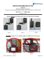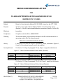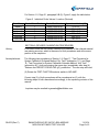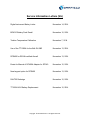
1
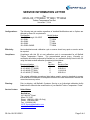
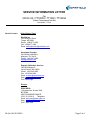
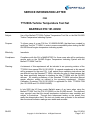
 Service Information Letters (SIL)
Digital Instrument Battery Letter
November 14, 2014
BP4010 Battery Pack Recall
November 12, 2014
Turbine Temperature Calibration
November 7, 2014
Use of the TT1200A for the Bell OH-58D
November 13, 2014
DPS400 for RSVM-certified Aircraft
November 13, 2014
Errata for Manual of DC400A Adapter for SF340
November 12, 2014
New keypad option for DPS400
November 13, 2014
DALT55 Redesign
November 12, 2014
TT1000A 45V Battery Replacement
November 12, 2014
Copyright © 2014 Barfield Inc. All Rights Reserved. SERVICE INFORMATION LETTER
Regarding
DALT55 & DAS650 Instruments
Instrument can be damaged during Battery charge cycle when using BP4010 / SC3000 charger while
attached to instrument.
Recall on BP4010 battery pack
November 12, 2014
Subject:
Possible damage to the DALT55 & DAS650 Instruments may occur while charging the
BP4010 battery pack using the SC3000 charger if the BP4010 is installed on the Test Set
during charging.
CAUTION
Remove the BP4010 battery pack from the test set before charging when
using the SC3000 charger. (See page 3, Figure 4 & 5)
Note: For customers charging the BP4000 or BP4010 battery pack using the Barfield
Smart charger (p/n: 137-00012), there are no issues. (See page 3, Figure 1 & 2)
The figures on page 3 clearly identify ALL possible battery pack / charger
configurations to easily identify which configuration the above CAUTION is
addressing and the configurations that work fine and are no concern.
Purpose:
To notify customers of a potential problem that exists and how to avoid damaging the
DALT55 and or DAS650 Instruments.
History:
Recently Barfield has determined that approximately 3% of the units sold during the past
24 months have instruments (DALT55 / DAS650) that were damaged as a result of
charging the BP4010 battery pack using the SC3000 charger.
Barfield is working quickly to provide a permanent solution for this problem and will
advise customers as soon as possible when the solution is available. As mentioned
above, customers using the Smart charger (p/n: 137-00012) are not affected, only
customers with the SC3000 chargers.
Note: The damage, when it occurs, results in the instruments not powering on and the
instruments will remain inoperative. If the Instrument power is on, and the recommended
calibration interval has been followed, the user can continue using the Instruments with
confidence. Barfield requests that the user follow the CAUTION as detailed above.
Configurations:
All 1811-A0A configurations using the BP4010 battery pack and the SC3000 charger.
All DALT55 and or DAS650 configurations using the BP4010 battery pack and the
SC3000 charger.
Effectivity:
Immediately.
Compliance:
Immediate compliance with this SIL is recommended to avoid the possibility of damaging
your DALT55 and DAS650 instruments.
SIL No: 88-102-02111-1 (Rev C)
Copyright © 2014 Barfield Inc. All Rights Reserved.
Page 1 of 3
SERVICE INFORMATION LETTER
Regarding
DALT55 & DAS650 Instruments
Instruments can be damaged during Battery charge cycle when using BP4010 / SC3000 charger.
Recall on BP4010 battery pack
November 12, 2014
Planning:
Prior to shipping your BP4010 battery pack for warranty consideration, call customer
service to confirm availability of BP4015 (P/N: 137-00030) battery pack.
Barfield will not have inventory of the new BP4015 prior to December 2012.
As a short term solution while waiting for availability of BP4015, continue using the
BP4010 battery pack and following the CAUTION detailed on page 1 and illustrated in
Figures 1, 2 & 3 on page 3.
Conclusion:
Barfield Inc. is taking a proactive approach in reaching out to its customers and advising
them of this charging issue. The short term solution is to remove the BP4010 from the
test set while charging using the SC3000 (P/N: 137-00021) charger.
Barfield is working on a long term solution, correcting the BP4010 design and will provide
qualifying customers with a warranty replacement battery pack BP4015 when available.
Warranty
Consideration:
Barfield will provide a warranty exchange BP4015 battery pack only to customers that
send in their BP4010 battery pack(s).
As of December 2012, all customer units received for calibration or repair will
automatically get a replacement BP4015 if their test set has a BP4010 battery pack.
Note: Do not send in your BP4010 for replacement consideration until notified or
confirming that the BP4015 is available.
Barfield is committed to providing the highest quality products, services and support to
the aviation industry. Inquiries may be emailed to [email protected].
Thank you for your business and support.
Robert Arnett,
VP Quality
SIL No: 88-102-02111-1 (Rev C)
Page 2 of 3
SERVICE INFORMATION LETTER
Regarding
DALT55 & DAS650 Instruments
Instruments can be damaged during Battery charge cycle when using BP4010 / SC3000 charger.
Recall on BP4010 battery pack
November 12, 2014
Always remove the battery pack from Test Set before charging:
Smart Charger (P/N: 137-00012)
BP4000 Battery Pack (P/N: 137-00009)
Figure 1
Smart Charger (P/N: 137-00012)
BP4010 Battery Pack (P/N: 137-00020)
SC3000 Charger (P/N: 137-00021)
BP4010 Battery Pack (P/N: 137-00020)
Note: BP4010 is removed from Test Set
Figure 2
Figure 3
DO NOT charge BP4010 battery while it is attached to the test set:
Figure 4
SIL No: 88-102-02111-1 (Rev C)
Figure 5
Page 3 of 3
SERVICE INFORMATION LETTER
For
2312G-XX / TT1000A / TT1200 / TT1200A
Turbine Temperature Test Set
November 7, 2014
Subject:
Usage of obsolete documentation in the calibration of the Barfield Turbine Temperature
Tester product lines.
Purpose:
The concern Barfield Inc. (Barfield) has is that obsolete Technical Manuals and
calibration procedures widely distributed via the internet are being used in the
certification of the Barfield Turbine Temperature Tester products. The obsolete
technical documentation contains calibration standards and procedures which no longer
meet Barfield or industry standards and should not be used in the service of Barfield
equipment. In an effort to ensure that Barfield products maintain quality, accuracy and
industry standards, Barfield has reviewed and revised the calibration procedures for our
Models 2312G-XX, T1000A, TT1200, TT1200A Turbine Temperature Test sets.
Below are the calibration procedures which have now been made obsolete:
Document Number
Old
Revision
Old
Revision Date
57-101-00550 (2312-XX)
19-101-00901 (TT1000A)
57-101-00901 (TT1000A)
20-101-00920-1 (TT1200)
19-101-00930 (TT1200A)
N/A
C
N/A
A
E
Nov 30, 1983
Oct 4, 2011
Sept 28, 1984
Nov 20, 1995
Nov 18, 2010
This is a concern for those customers that have their units calibrated by a facility not
using the authorized calibration standard and/or procedures. For these customers we
recommend returning your unit(s) to Barfield or an authorized service facility listed in
this letter for calibration / verification service to ensure that operational and accuracy
compliance is maintained.
SIL No: 88-101-00901
Page 1 of 4
Copyright © 2014 Barfield Inc. All Rights Reserved.
SERVICE INFORMATION LETTER
For
2312G-XX / TT1000A / TT1200 / TT1200A
Turbine Temperature Test Set
November 7, 2014
Configurations:
The following test set models, regardless of installed Modifications and or Options are
affected by these SIL requirements:
Part Number
101-00550 through 101-00557
101-00901
101-00920
101-00930
101-00930-OH58D
Model Number
2312G-XX
TT1000A
TT1200
TT1200A
TT1200A
Effectivity:
Next scheduled annual calibration cycle or sooner should any repair or service action
be required.
Compliance:
Compliance with this SIL at next calibration cycle is recommended for all Barfield
Turbine Temperature Testers. The recommended annual (every 12-month) recertification should be performed by Barfield Inc. or a calibration facility listed in this SIL
using the latest revised calibration procedure(s) listed below:
New
New
Document Number
Revision
Revision Date
19-101-00550 (2312-XX)
B
11/12/2014
19-101-00901 (TT1000A)
E
9/19/2014
19-101-00920 (TT1200)
C
11/12/2014
19-101-00930 (TT1200A)
G
9/25/2014
The revised calibration procedures listed above employ superior standards to ensure
that calibration uncertainties of acceptable tolerance for each characteristic maintain the
correct test accuracy ratios.
Planning:
Prior to shipping, call Barfield’s Customer Service or an Authorized calibration facility
listed below to schedule the recertification of your Barfield Turbine Temperature Tester.
Service Centers:
United States
Barfield Inc.
4101 NW 29th Street
Miami, FL 33127
Phone: 1-800-321-1039 (US Only)
Phone: 1-305-894-5400
Fax: 1-305-894-5401
[email protected]
www.barfieldinc.com
SIL No: 88-101-00901
Page 2 of 4
SERVICE INFORMATION LETTER
For
2312G-XX / TT1000A / TT1200 / TT1200A
Turbine Temperature Test Set
November 7, 2014
Service Centers:
United States (Cont)
Barfield Inc.
1912 West 4th Street
Tempe, AZ 85281
Phone: 1-480-477-2000
Fax: 1-480-477-1999
Email: [email protected]
Aeroframe Airepairs
3914 Willow Lake Blvd.
Memphis, TN. 38118
Phone: 1-901-547-4600
[email protected]
Express Calibration Services
1803 SW Market St.
Lee’s Summit, MO 64082
Phone: 1-816-246-9292
Fax: 1-816-246-9295
Email: [email protected]
Web: www.expresscal.com
POC: Mike Sage
Europe:
EADS SECA
1 Boulevard du 19 mars 1962
BP 50064
95503 GONESSE FRANCE
33 01 30 18 54 12
Telephone
Email: [email protected]
Web: www.seca.eads.net
POC: Jean Paris
SIL No: 88-101-00901
Page 3 of 4
SERVICE INFORMATION LETTER
For
2312G-XX / TT1000A / TT1200 / TT1200A
Turbine Temperature Test Set
November 7, 2014
Service Centers:
Canada:
Wright Instruments Ltd
2762 Slough St,
Mississauga ON, L4T 1G3
Phone: (905) 677-7161
Australia:
TR VMS
72 Donaldson Road
Rocklea, 4106
QLD, Australia
Ph: 61 7 3717 9146
Fax: 61 7 3717 9135
Web: www.trvms.com.au
Conclusion:
Barfield Inc. is taking a proactive approach in reaching out to its customers and advising
them of the potential for unauthorized facilities calibrating our turbine temperature test
equipment using obsolete documentation as described above. Barfield strongly
recommends the return of ALL units at their next calibration / recertification interval to a
Barfield facility or one of the listed authorized calibration facilities to ensure the
equipment is performing as designed and in compliance with new test procedures,
calibration standard and accuracy requirements.
Barfield is committed to providing the highest quality products, services and support to
the aviation industry.
Inquiries may be emailed to [email protected].
Thank you for your business and support.
Robert Arnett
VP Quality
SIL No: 88-101-00901
Page 4 of 4
SERVICE INFORMATION LETTER
FOR
TT1200A Turbine Temperature Test Set
BARFIELD P/N 101-00930
Subject:
Use of the Barfield TT1200A Turbine Temperature Test Set on the Bell OH-58D
Turbine Temperature Indicating System
Purpose:
To inform users of a new P/N, the 101-00930-OH58D, that has been created by
modifying Test Set TT1200A, in order to ensure compatibility when testing the Bell
OH-58D aircraft engine temperature indicating system.
Effectivity:
Immediate
Compliance:
Compliance with this SIL is MANDATORY for those users who will be performing
service work on the OH-58D Engine Temperature Indicating System with the
Barfield TT1200A Test Set.
Planning:
A statement of this requirement will be included in an upcoming revision of the
TT1200A User manual P/N 56-101-00930. A separate supplement to this manual
will be prepared for the new P/N. It will explain those operating instructions that
are different from the Standard TT1200A, including the use of a new harness that
has been specifically designed to interface the new TT1200A with the OH-58D
airframe. All existing procedures of the Standard TT1200A Instruction Manual
remain effective, except as outlined in the upcoming supplement. Existing
Calibration Procedure P/N 20-101-00930 is applicable for both TT1200A P/Ns
(the 101-00930 and 101-00930-OH58D).
History:
In late 2000 the US Army made Barfield aware of an issue when using the
Barfield TT1200 Test Set (P/N 101-00920) on the OH-58D aircraft. The observed
error reported was that the aircraft temperature indications were unstable and
subject to fluctuations. Through their subsequent testing on the aircraft they
made the determination that if the test set chassis was grounded to the airframe
then the aircraft indicator readings were stable and accurate.
SIL005
Copyright © 2014 Barfield Inc. All Rights Reserved.
Nov/ 13 / 2014
Page 1 of 2
Based on these reported findings and their request for an embedded solution,
Barfield developed a modification for the TT1200 designated as Option A. This
Option consisted of a modification to the TT1200 Test Set panel connector wiring
as well as the test set interface cables so that the test set chassis ground was
provided by an added third clip lead to the testers cables so as to provide a
ground strap to the airframe chassis.
The US Army subsequently procured some number of these Option A configured
TT1200 testers specifically for use on the OH-58D aircraft and used them
thereafter without report of any further issues.
The TT1200 was made obsolete upon the introduction of the TT1200A Test Set in
2003. The model TT1200A (P/N 101-00930) is an all-new test set sharing no
subassemblies with the earlier TT1200 tester (P/N 101-00920). The TT1200A is
not a suitable substitute for the TT1200 with Option A.
There was no provision made for grounding the TT1200A Test Set to the airframe
as the necessity for doing so is, to our knowledge, unique to the OH-58D aircraft
and its installed equipment and wiring configuration. Barfield has never been
made aware of any other aircraft engine temperature indicating system which
necessitated this grounding for correct operation.
Conclusion:
The TT1200A test set can be ordered preconfigured for singular use on the OH58D aircraft, under the new Barfield P/N 101-00930-OH58D. This newly modified
Test Set TT1200A is provided with a specific harness, designed to interface it with
the aircraft. The only two Barfield-approved Testers for the Engine Temperature
Indicating System of the OH-58D airframe are: the TT1200 with Option A, and the
new P/N 101-00930-OH58D.
Inquiries may be emailed to [email protected].
SIL005
Nov/ 13 / 2014
Page 2 of 2
SERVICE INFORMATION LETTER
FOR
DPS400 (P/N 101-01180) Pitot-Static Test Set
Subject:
Using the Barfield DPS400 Test Set is on RVSM Certified Aircraft.
Regarding compliances with RVSM, Barfield Inc. defines compliance as
meeting or exceeding the widely accepted RVSM test equipment (Ps) “static
channel” accuracy specification of ±0.0030 inHg.
Purpose:
To inform users how to clearly identify if their DPS400 test set configuration is in
compliance to meet / exceed the RVSM accuracy requirement.
Configurations:
The following configurations meet or exceed RVSM accuracy requirements:
ALL DPS400 (s/n up to 108, must have MOD “H” & “L”)
All DPS400 (s/n: 109 thru 289 must have MOD “G” & “L”).
All DPS400 (s/n 290 and higher must have MOD “G”)
Effectively:
Immediate
Compliance:
Compliance with this SIL is MANDATORY for those users who will be performing
service work on aircraft which are RVSM certified. The DPS400 requires annual
(every 12-month) re-certification performed by Barfield or an approved calibration
facility to ensure continued compliance with RVSM accuracies and proper test set
operation.
Planning:
For customers with DPS400 s/n 108 or lower, verify unit I.D. plate indicates both MOD
“H” & “L”.
For customers with DPS400 s/n 109 to 289, verify unit I.D. plate indicates both MOD
“G” & “L”.
For customers with DPS400 s/n 290 and above, verify unit I.D. plate indicates MOD
“G”.
If test set MOD level is does not include the MOD levels described above, contact
Barfield customer service.
Conclusion:
ALL DPS400 Test Sets that meet the above described MOD levels and are calibrated
on an annual (12-month cycle) by Barfield Inc. or an approved calibration facility are in
compliance with the accuracy requirements of RVSM.
Inquiries may be emailed to [email protected].
Novmber 13, 2014
Page 1 of 1
SIL006
Copyright © 2014 Barfield Inc. All Rights Reserved.
SERVICE INFORMATION LETTER
FOR
DC-400A ADAPTER MODULE FOR SAAB-FAIRCHILD SF-340
BARFIELD P/N 101-00809
Subject:
Errata for User Instruction Manual 56-101-00809, Issued on Jan. 29th, 1988
Purpose:
To inform users of the referred Adapter Module of revised testing values
(Section 1 of this SIL) and revised calibration procedures (Section 2 of this SIL).
Effectivity:
Immediate.
Compliance:
Compliance with this SIL is MANDATORY.
Planning:
The revised values and procedures indicated in this SIL will be included in an
upcoming revision B of the referred manual.
SECTION 1 (REVISED TESTING VALUES)
History:
It has been found that the range of capacitance values, indicated in Figures 1,
2, and 5 of the referred manual, need to be modified.
Accomplishment:
For Section 1-2, Page 4, paragraph 3.C.(2), Figure 1, apply the table below.
Figure 1 Table of Inboard Individual Probe Values (Revised)
Tank Group
Inboard
Inboard
Inboard
Probe Select Position
1
2
3
Probe Part Number
40007-0000-0101
40007-0000-0102
40007-0000-0103
Capacitance Value (pF)
4.1 ± 0.5
28.1 ± 0.5
29.3 ± 0.5
For Section 1-2, Page 5, paragraph 3.D.(2) (b), Figure 2, apply the table below.
Figure 2 Table of Outboard Individual Probe Values (Revised)
Tank Group
Outboard
Outboard
Outboard
SIL003 (Rev C)
Probe Select Position
1
2
3
Probe Part Number
40008-0000-0101
40008-0000-0102
40008-0000-0103
Capacitance Value (pF)
23.2 ± 0.5
20.8 ± 0.5
19.3 ± 0.5
SAAB-FAIRCHILD SF-340 DC-400A MODULE
NEW CAPACITANCE TEST VALUES
Copyright © 2014 Barfield Inc. All Rights Reserved.
11/13/14
Page 1 of 2
For Section 1-2, Page 21, paragraph 9.B.(2), Figure 5, apply the table below.
Figure 5 Individual Probe Values / Location (Revised)
Tank Group
Inboard
Inboard
Inboard
Outboard
Outboard
Outboard
Probe Select Position
1
2
3
1
2
3
Probe Part Number
40007-0000-0101
40007-0000-0102
40007-0000-0103
40008-0000-0101
40008-0000-0102
40008-0000-0103
Capacitance Value (pF)
4.1 ± 0.5
28.1 ± 0.5
29.3 ± 0.5
23.2 ± 0.5
20.8 ± 0.5
19.3 ± 0.5
SECTION 2 (REVISED CALIBRATION PROCEDURES)
History:
It has been found that two related calibration procedures of the referred manual
are missing one step, which is the same for both procedures and at the same
position in the sequence.
Accomplishment:
The following two procedures of Section 1-2: Page 17, “Test Procedure for
System Calibration Preferred Method, Dry Tank” (subsection 7.C), and Page
19, “Test Procedure for System Calibration Alternate Method, Wet Tank”
(subsection 8.C), both are missing the same step, immediately after step (4)
“Release the PRESS TO READ CAP (pF) pushbutton.” The new step will read:
(5) Rotate the TEST FUNCTION selector switch to IND AMP.
Current step (5) of both procedures will be renumbered as (6), with the
following steps of both renumbered accordingly, in the upcoming revision of this
manual.
Inquiries may be emailed to [email protected].
SIL003 (Rev C)
SAAB-FAIRCHILD SF-340 DC-400A MODULE
NEW CAPACITANCE TEST VALUES
11/13/14
Page 2 of 2
SERVICE INFORMATION LETTER
FOR
DPS400
BARFIELD P/N 101-01180
Subject:
DPS400 New Option Available
Purpose:
To inform customers of a new custom fit option choice for the keypad
assembly for the Barfield P/N 101-01180, Digital Pitot Static Tester
Effectivity:
All DPS400 Testers with serial number 443 or greater and produced from
January 2001. (Note: Units with serial numbers lower than 443 must be sent
to Barfield for evaluation.)
Compliance:
Compliance with this SIL is OPTIONAL.
Planning:
Option C involves a choice for a membrane keypad assembly
History:
The display assembly has been updated to use a membrane keypad to
replace the mechanical switch assembly. This new membrane assembly will
reduce assembly labor time, repair costs and will provide a new key on the
keyboard (engraved PUMP) which will allow operators to turn the pumps ON
and OFF.
Accomplishment:
New production units will be fitted with the membrane keypad option as a
production standard build. This build will be documented as Option C. The
Test Set maintenance menu will be configured via firmware 33R06N5 to
support the new membrane keypad.
Customers with field serviceable units interested in this option will need to
contact Barfield Sales Department or Customer Technical Support
(800-321-1039) for further information or to arrange a return to obtain this
new option.
Inquiries may be emailed to [email protected].
SIL002 (Rev B)
DPS400
NEW OPTION AVAILABLE
Copyright © 2014 Barfield Inc. All Rights Reserved.
11/13/14
Page 1 of 1
SERVICE INFORMATION LETTER
For
DALT55 Digital Altimeter
November 12, 2014
Subject:
Redesign of the Barfield Model DALT55.
Note: For those customers that returned their test set to Barfield for the annual
recertification, there is no issue with continued use of these units.
Purpose:
This letter is to inform customers that Barfield Inc. has recently redesigned the DALT55
Digital Altimeter. As a result of the redesign, model number DALT55 will not be affected
but part number 101-02184 is replaced with a new part number 101-02186. The new
part number (part number 101-02186) altimeter is a 100% Form-Fit-Function
replacement for the replaced unit (part number 101-02184).
History:
Due to procurement issues with critical components, Barfield Inc. designed a new Model
Number DALT55 Digital Altimeter Part Number 101-02186.
Configurations:
The following configurations are affected by this design:
Model Number
Part Number
1811D-A0A
101-00164-A0A
1811GA-A0A
101-00185-A0A
1811HA-A0A
101-00184-A0A
DALT55
101-02184
Note: Products containing either part number 101-02184 or 101-02186 Digital
Altimeters meet the requirements described in Federal Aviation Regulation Part 43
Appendix-E which defines the requirements for accuracy of an aircraft’s altimeter and is
used as a reference for the accuracy of Pitot-Static testers. These products however do
not meet RVSM accuracy requirements.
Effectivity:
All newly manufactured test sets listed in above configurations will contain a DALT55
with part number 101-02186. Any units received for service determined to have a
transducer failure (part number PDCR2200-8860) will require update to new part
number. Update would include new transducer, manifold, PC board and hardware to
convert to new part number 101-02186.
Compliance:
No compliance requirement.
Specifications:
SIL No: 88-101-02184-B
Page 1 of 4
Copyright © 2014 Barfield Inc. All Rights Reserved.
SERVICE INFORMATION LETTER
For
DALT55 Digital Altimeter
November 12, 2014
Specifications for the discontinued Barfield DALT55 part number 101-002184.
DALT55 (P/N 101-02184)
RANGE
-1500 to 55,000 ft
ACCURACY
0.025% Typical FS over complete operating temperature range.
Specific accuracies at certain altitudes are:
Altitude
Altitude
-1,500 Ft
± 7 Ft
30,000 Ft
± 20 Ft
0 Ft
± 7 Ft
40,000 Ft
± 30 Ft
10,000 Ft
± 10 Ft
50,000 Ft
± 48 Ft
20,000 Ft
± 14 Ft
55,000 Ft
± 62 Ft
Note: When displaying altitude in Ft: Feet or M: Meters, the pressure
altitude calculation is based on a baro set of 29.921 inHg = 1013.2 mb.
Note: The Baro Set value cannot be changed, it is set at 29.921 inHg.
STABILITY
0.05% FS (Typical) over 12 months.
Note: This tolerance represents the typical stability over a 12 month
period. If tighter tolerances are required, the calibration interval should be
reduced or establish proof of stability.
PRESSURE RANGE
ROC
3.425 inHg to 32 inHg absolute
LEAK TEST MODE
Measures Leak Rate
After 1 minute of stabilization and the minimum of 1 minute Leak
Test Interval, the Leak Test accuracy:
± 3 Ft/min
± 1 M/min
TEMPERATURE RANGE:
OPERATING: -10º C to 50º C (-4° F to 122° F)
VSI (Vertical Speed Displayed)
± 50 Ft/min (VSI > 150 Ft/min)
± 10 M/Min (VSI > 40 M/min)
Note: Displays “0” below 100 Ft/min & 30 M/min
STORAGE:
SIL No: 88-101-02184-B
-30º C to 60º C (-22° F to 140° F)
Page 2 of 4
SERVICE INFORMATION LETTER
For
DALT55 Digital Altimeter
November 12, 2014
Specifications for the new Barfield DALT55 part number 101-002186.
DALT55 (P/N 101-02186)
ALTITUDE RANGE
-1,500 to 55,000 ft
ACCURACY
0.020% FS Typical, 0.040% FS (Max) over complete operating
temperature range. Specific accuracies at certain altitudes are:
Altitude
Altitude
-1,500 Ft
± 7 Ft
30,000 Ft
± 20 Ft
0 Ft
± 7 Ft
40,000 Ft
± 30 Ft
10,000 Ft
± 10 Ft
50,000 Ft
± 48 Ft
20,000 Ft
± 14 Ft
55,000 Ft
± 62 Ft
Note: When displaying altitude in Ft: Feet or M: Meters, the pressure
altitude calculation is based on a baro set of 29.921 inHg = 1013.2 mb.
Note: The Baro Set value cannot be changed, it is set at 29.921 inHg.
STABILITY
0.025% FS (Max) over 12 months.
Note: This tolerance represents the stability over a 12 month period. If
tighter tolerances are required, the calibration interval should be reduced
or establish proof of stability.
PRESSURE RANGE
ROC
3.425 inHg to 38 inHg absolute
LEAK TEST MODE
Measures Leak Rate
After 1 minute of stabilization and the minimum of 1 minute Leak
Test Interval, the Leak Test accuracy:
± 3 Ft/min
± 1 M/min
TEMPERATURE RANGE:
OPERATING: -10º C to 50º C (-4° F to 122° F)
VSI (Vertical Speed Displayed)
± 50 Ft/min (VSI > 150 Ft/min)
± 10 M/Min (VSI > 40 M/min)
Note: Displays “0” below 100 Ft/min & 30 M/min
STORAGE:
SIL No: 88-101-02184-B
-30º C to 60º C (-22° F to 140° F)
Page 3 of 4
SERVICE INFORMATION LETTER
For
DALT55 Digital Altimeter
November 12, 2014
Planning:
Prior to shipping, call customer service to schedule the recertification of your Pitot-Static
Test Set.
Conclusion:
Barfield Inc. is taking a proactive approach in advising its customers of the newly
designed Digital Altimeter used in our pitot-static products. Barfield recommends the
return of ALL units at their next calibration / recertification interval so that Barfield as
OEM, can ensure the equipment is performing as designed and in compliance with
accuracy requirements.
Barfield is committed to providing the highest quality products, services and support to
the aviation industry.
Inquiries may be emailed to [email protected].
Thank you for your business and support.
Robert Arnett
VP Quality
SIL No: 88-101-02184-B
Page 4 of 4
SERVICE INFORMATION LETTER
For
TT1000A
Turbine Temperature Test Set
November 12, 2014
Subject:
Obsolescence and replacement of a critical component within the Barfield TT1000A.
Purpose:
In June 2012 Barfield Inc. (Barfield) was informed by the Eveready Battery Company
that a critical component used in the TT1000A product has been made obsolete.
Eveready Part number 415 a 45V Carbon Zinc Battery NEDA 213 is no longer
manufactured and has very limited availability. The Eveready 415 is used in the
TT1000A to provide the required 45 volt excitation for testing the Insulation breakdown
of the aircraft EGT/IGT system and other Type K thermocouple based systems.
Barfield was unable to identify a Form-Fit-Function (FFF) replacement for the 415
battery.
Configurations:
The following test set model, regardless of installed Modifications and or Options is
affected by this SIL recommendation:
Part Number
101-00901
Model Number
TT1000A
Purpose:
Replacement of the 45V battery.
Solution:
Barfield has a newly designed replacement module “45V Battery Replacement
Converter” to mimic the operational specifications and capabilities of the Eveready 415
45V battery. Barfield part number 137-08001 is a module designed to be used with an
off-the-shelf 9V alkaline battery to produce the 45V output voltage needed to properly
operate the Barfield TT1000A. Unless damaged the 137-08001 does not require
replacement in the future, only the 9V Battery. This solution achieves two goals, first is
to replace the obsolete Eveready 415 battery and second replaces a specialty battery
having a limited availability with an off-the-shelf solution available internationally.
Compliance:
Customer compliance with this SIL is optional. The obsolete Eveready 415 battery is
considered a consumable part thus will require eventual replacement as they fail.
All new Barfield TT1000A Turbine Temperature Testers manufactured after April, 2013
will include the new 137-08001 module and 9V battery. Any 45V Batteries identified as
unserviceable during a repair or calibration activity should be replaced with new 13708001.
SIL No: 88-101-00901-1
Copyright © 2014 Barfield Inc. All Rights Reserved.
Page 1 of 4
SERVICE INFORMATION LETTER
For
TT1000A
Turbine Temperature Test Set
November 12, 2014
Availability:
The 137-08001 will be stocked by Barfield and our authorized distributors and service
centers beginning May 2013. Please call Barfield’s Customer Service or an Authorized
calibration facility listed below to purchase a 137-08001 45V Battery Replacement
Converter or schedule the recertification of your Barfield Turbine Temperature Tester.
Installation:
Installation of the 137-08001 45V Battery Replacement Converter is outlined in
Barfield document 60-137-08001.
Service Centers:
United States
Barfield Inc.
4101 NW 29th Street
Miami, FL 33127
Phone: 1-800-321-1039 (US Only)
Phone: 1-305-894-5400
Fax: 1-305-894-5401
[email protected]
www.barfieldinc.com
Barfield Inc.
1912 West 4th Street
Tempe, AZ 85281
Phone: 1-480-477-2000
Fax: 1-480-477-1999
Email: [email protected]
Aeroframe Airepairs
3914 Willow Lake Blvd.
Memphis, TN. 38118
Phone: 1-901-547-4600
[email protected]
SIL No: 88-101-00901-1
Page 2 of 4
SERVICE INFORMATION LETTER
For
TT1000A
Turbine Temperature Test Set
November 12, 2014
Service Centers:
United States (Cont)
Express Calibration Services
1803 SW Market St.
Lee’s Summit, MO 64082
Phone: 1-816-246-9292
Fax: 1-816-246-9295
Email: [email protected]
Web: www.expresscal.com
POC: Mike Sage
Europe:
EADS SECA
1 Boulevard du 19 mars 1962
BP 50064
95503 GONESSE FRANCE
33 01 30 18 54 12
Telephone
Email: [email protected]
Web: www.seca.eads.net
POC: Jean Paris
Service Centers:
Canada:
Wright Instruments Ltd
2762 Slough St,
Mississauga ON, L4T 1G3
Phone: (905) 677-7161
SIL No: 88-101-00901-1
Page 3 of 4
SERVICE INFORMATION LETTER
For
TT1000A
Turbine Temperature Test Set
November 12, 2014
Service Centers:
Australia:
TR VMS
72 Donaldson Road
Rocklea, 4106
QLD, Australia
Ph: 61 7 3717 9146
Fax: 61 7 3717 9135
Web: www.trvms.com.au
Barfield is committed to providing the highest quality products, services and support to
the aviation industry. Additional service centers are being evaluated and approved to
better serve our customer. Please visit the Barfield Inc. website for the most up-to-date
list of service centers.
Inquiries may also be emailed to [email protected].
Thank you for your business and support.
Robert Arnett
VP Quality
SIL No: 88-101-00901-1
Page 4 of 4