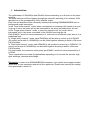
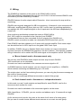
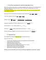
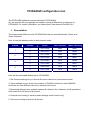
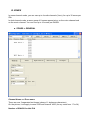
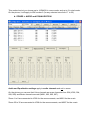
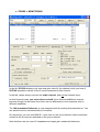
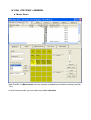
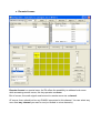
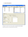
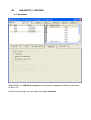
1
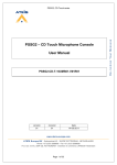
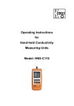
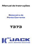
Ateis International
Stéphane Lesage
IDA4 in switching application
with the new IDA4SW 1.2.x
IDA4 in switching application with the new IDA4SW............................................................1
I. Introduction ...............................................................................................................2
II. Wiring........................................................................................................................3
a. Mono channel mode = Announcement only ..........................................................3
b. Dual channel mode = Announces + independent music........................................3
III.
PA/VA system design rules with IDA4SW .............................................................6
a. Audio output Channel and Zone allocation............................................................6
b. Impedance error tolerance constraint ....................................................................6
c. End of line capacitors for sufficient Impedance error.............................................7
d. Capacitors.xls ........................................................................................................7
PCIDA4SW configuration tool..............................................................................................8
I. Presentation..............................................................................................................8
II. SITE > GENERAL.....................................................................................................9
III.
ZONES ................................................................................................................10
a. ZONES > GENERAL ...........................................................................................10
b. ZONES > AUDIO and EQUALIZATION...............................................................11
c. ZONES > MONITORING.....................................................................................12
IV.
CALL STATIONS > GENERAL ...........................................................................13
a. Music Zones ........................................................................................................13
b. Local Zones / Remote Access / Mic-Chime Direct...............................................14
V. EVACUATION INPUTS...........................................................................................16
VI.
CONTROL INPUTS > ROUTING ........................................................................17
VII. 0dB INPUTS > ROUTING ...................................................................................18
a. Permanent ...........................................................................................................18
b. Modulation detection ...........................................................................................19
IDA4SW line-monitoring Tests...........................................................................................20
I. Functioning principle and possibilities .....................................................................20
a. Mono channel mode ............................................................................................20
b. Dual channel mode..............................................................................................20
II. Tests in background monitoring mode ....................................................................21
a. Zone defects BEGINNING detection ...................................................................21
b. Zone defects END detection................................................................................21
c. Channel defects detection in mono-channel mode..............................................21
d. Channel defects detection in dual-channel mode ................................................21
III.
Tests while announces ........................................................................................22
a. Zone defects BEGINNING detection ...................................................................22
b. Channel defects detection in mono-channel mode..............................................22
c. Channel defects detection in dual-channel mode ................................................22
I. Introduction
The combination of IDA4SW(s) and IDA4SU allows connecting up to 8 zones to the same
amplifier.
The zone selection will then happen through the automatic switching of the relevant 100V
speaker line to the corresponding 100V amplifier output.
Each line and amplifier will be constantly monitored according EN60849/BS5839 with no
background music interruption.
In the ‘’Dual audio channel’’ mode, when a microphone or message call is made in a zone
or group of zone, the music will not be interrupted in the zones not selected for the call.
In the ‘’Single audio channel’’ mode, in case of a selective call, the music will be
interrupted only in the zones connected to the IDA4SU receiving the call.
Each IDA4SU, and the 8 zones connected to it, could receive a different music source to a
predefined level.
In ‘’Single audio channel’’ mode, each IDA4SW(s) will be able to control up to 4 IDA4SU
(32 zones) and a total of 4 IDA4SW(s) can be linked together allowing to build a 128 zones
PA/VA system.
In ‘’Dual audio channel’’ mode, each IDA4SW(s) will be able to control up to 2 IDA4SU (16
zones) and a total of 8 IDA4SW(s) can be linked together allowing to build a 128 zones
PA/VA system.
For both modes, the maximum audio power per IDA4SU, and the 8 zones connected to it,
is 500W.
Those combinations are ideal for applications requesting a lot of zones like schools, high
raise buildings, commercial buildings…
Disclaimer: in order to be EN60849/BS5839 compliant, your system must respect certain
constraints on line impedance and end of line capacitors. Please read carefully the design
rules presented in section III.
II. Wiring
The IDA4SW(s) hardware is the same as the IDA4(X)(M)(s) series.
100V line switching is performed through the use of one or several external IDA4SU units
controlled by the new IDA4SW(s) firmware.
IDA4SW features 4 audio outputs called Channels + in/out connectors for amp and line
monitoring.
IDA4SU was originally designed for A/B line monitoring. It features 4 in/out connectors for
0dB audio, amplifier and A/B lines, plus one 100 V music input. In switching application,
we replicate the 100V amplified signal on the 4 inputs and use A/B lines independently for
a total of 8.
Amp monitoring and backup remains the same as IDA4(X)(M)(s).
One 100V output is connected to the 4 inputs of one IDA4SU.
Loudspeakers lines are then connected on the 8 outputs of an IDA4SU unit.
IDA4SU control connection is made via a chainable RS232 serial link. (port 3)
Each IDA4SU can then address up to 8 zones with a single amplifier. Each zone output
can be switched on its 100V input or on the global 100V music input.
In addition, IDA4SU can go in ‘Bypass Mode’ when it does not receive commands
anymore, because the IDA4SW has crashed or the link is broken. This requires complete
wiring to allow the unit to switch the PSS audio signal on the amplifier and all 100V lines.
a. Mono channel mode = Announcement only
We use only one IDA4SW(s) audio output and one amp for each IDA4SU.
100V music input is not connected.
So each zone can be switched on the common announce signal or off.
As IDASW features 4 audio outputs, you can connect up to 4 amplifiers + 4 IDA4SU,
which enables monitoring and addressing up to 32 zones.
The single output on the 8 zones being the same, you can only play the same message on
the zones of a same group.
But you can of course page different announces on each of the groups.
b. Dual channel mode = Announces + independent music
In this mode, we use 2 audio outputs and amplifiers for each IDA4SU: one for the
announces and another for music.
So each zone can be switched on the announce signal or on the music.
With 4 amplifiers + 2 IDA4SU, you can monitor and address up to 16 zones with a single
IDA4SW.
As for announce-only mode, the music is the same for all zones of a same group.
But you can of course choose different music sources or no music on each group.
III. PA/VA system design rules with IDA4SW
a. Audio output Channel and Zone allocation
In switching application, you must be aware that the 8 zones of an IDA4SU are connected
to a single audio output. Consequently only 1 announcement can be made at a time.
Audio routing is done at the channel-level, and zone-switching occurs only after, if the
audio-source has the required priority.
Then if a new source with a higher priority takes the control of an audio channel, its zonelevel routing will replace the current switching state.
You must consider this when allocating audio channels and zones in your system. Zones
which can potentially be addressed by different sources at the same time must be placed
on different audio channels.
Note that IDA4SW is very flexible. It is not compulsory to fill all channels with 8 zones, and
you can connect any number of IDA4SU. Moreover, you still have the possibility to put a
single zone with its own amplifier on a free channel without using an IDA4SU.
For example, you can build a 14 zones system with 2 IDA4SU on 1 IDA4SW:
5 zones on channel 1, 8 zones on channel 2 and 1 zone on channel 3.
b. Impedance error tolerance constraint
In switching application, with up to 8 lines on the same amplifier, you can have a lot of
loudspeakers in parallel.
Detecting a cut line defect on only 1 line is therefore far more difficult because the error on
this single line will translate into a little amount on the whole group of 8 lines in parallel.
So, on the one hand, we have to set a low tolerance threshold.
On the other hand, total line impedance is not perfectly stable because of the variation of
temperature and pressure which typically causes fluctuations up to 5% on the impedance
measure. So the tolerance threshold must be greater than 5%.
Consequently, you must make sure than a cut line defect on any line will cause an
impedance error greater than 10%, by adding end of line capacitors on each line.
c. End of line capacitors for sufficient Impedance error
End of line capacitors are used to increase impedance error when the line is cut anywhere.
When the capacitor is removed from the line, it will cause an additional error on the
impedance measure.
By choosing a sufficient value, we can make sure that it will cause an error greater than
the tolerance threshold.
We have the total loudspeakers impedance and 8 capacitors: ¨
If we lose a capacitor we have
Relative error is e =
1
1
8
=
+
Z Z LINES Z CAPA
1
1
7
=
+
Z E Z LINES Z CAPA
Z LINES
8 × Z LINES + Z CAPA
ZE − Z
= 1−
=
Z
7 × Z LINES + Z CAPA 7 × Z LINES + Z CAPA
Capacitor impedance to achieve desired error is Z CAPA =
(1 − 7e)
× Z LINES
e
Then we want e > 10% , which leads to Z CAPA < 3 × Z LINES
We have Z =
1
, which is applicable at frequency f = 18 kHz
C.2πf
Finally the minimal capacitor than you must put on each line is C =
8841941
pF .
3 × Z LINES
d. Capacitors.xls
The supplied spreadsheet Capacitors.xls computes all for you.
What you have to do:
-
measure the loudspeakers-only lines impedances with PCIDA4SW.
put the values in the Excel file.
supply the desired relative error.
read the theoretical capacitor value.
choose the nearest available value that fits your needs.
add the capacitors at the end of the lines.
make the lines references with PCIDA4SW.
activate the monitoring on used channels
Finally, you must simulate an error by removing a capacitor to check your system
PCIDA4SW configuration tool
The PCIDA4SW software is almost identical to PCIDA4XM.
So, this manual will only highlight and explain news and differences in reference to
PCIDA4XM. For further information, you should read “User manual IDA4XM V2.x”.
I. Presentation
The fundamental difference with (PC)IDA4XM is that we now differentiate ‘Zones’ and
‘Audio Channels’.
Here is how the labeling works in dual-channel mode:
IDASW
1
2
3
4
IDA4SU
Zones
Voice channel
Music channel
1
Z001-Z008
V002
M001
2
Z009-Z016
V004
M003
3
Z017-Z024
V006
M005
4
Z025-Z032
V008
M007
5
Z033-Z040
V010
M009
6
Z041-Z048
V012
M011
7
Z049-Z056
V014
M013
8
Z057-Z064
V016
M015
Here are the noticeable differences in PCIDA4SW:
1. Site General settings let you choose the mono-channel or dual-channel mode.
2. Zones settings let you choose the number of IDA4SU modules for each IDA4SW.
And there are now different names for channels and zones.
3. Monitoring settings have a global measure & reference for a channel, and 8 impedance
references for the 8 zones of a channel.
4. Channel-level routing is used for audio settings (audio levels & eq)
5. Zone-level routing is used for all the rest.
II. SITE > GENERAL
On PCIDA4SW, a checkbox let you choose between ‘Mono-channel’ and ‘Dual-channel’
modes.
III. ZONES
In mono-channel mode, you can use up to 4 audio channels (Vxxx), for up to 32 zones per
IDA.
In dual-channel mode, a same group of 8 zones appear twice, on the voice channel and
on the music channel. You can use up to 16 zones per IDASW.
a. ZONES > GENERAL
Channel Name and Zone name
There are now 2 separated text boxes (always 11 alphanum characters)
On the picture, it will apply to zone Z020 and channel V005 (for any zone from 17 to 24)
Number of IDA4SU for this IDA
This combo-box let you choose up to 4 IDA4SU in mono mode, and up to 2 in dual mode.
On the picture, it will apply to IDA number 2 (for any selected zone from 17 to 32).
b. ZONES > AUDIO and EQUALIZATION
Audio and Equalization settings apply to audio channels and not to zones.
On the picture you can see that Voice channels are even channels of an IDA (V002, 004,
008, 008) and Music channels are odd (M001, 003, 005, 007).
Zones 1 to 8 are connected to V002 for the annoucements, and M001 for the music.
Zones 25 to 32 are connected to V008 for the annoucements, and M007 for the music.
c. ZONES > MONITORING
In the list, Rf.G18k displays only one amp gain value for the channel, while you have 8
Rf.Z18k impedance values for the 8 zones connected to that channel.
In the tab, values always concern the audio channel, and not the selected zone.
In dual-channel mode, you must reference both Voice channel and Music channel,
because though it’s the same lines, there can be differences in the measures (due to
different amplifiers)
The 18k impedance Reference is now measured with all working lines switched on. You
can see the value is refreshed after a line defect.
On the picture, you can see 9999 Ω = ‘open line’ on the voice-channel, which is perfectly
normal as the 8 zones are switched on the music-channel.
Note that there are no more 1K impedance and open gain measures/references.
IV. CALL STATIONS > GENERAL
a. Music Zones
With IDA4SU v2, Music zones can now operate on zones (not limited to channels as SW
1.0.x)
In dual-channel mode, you can select only voice channels.
b. Local Zones / Mic-Chime Direct
Local PSS calls operate on zones.
In dual-channel mode, you can select only voice channels.
c. Remote Access
Remote Access is a special case. As IDA offers the possibility to address local zones
while accessing remote zones, this key operates on zones.
But of course, the audio signal must be sent to remote zones via a channel.
Of course, there should not be any IDA4SU connected to this channel. You can select any
zone from any channel you want to use (not limited to voice channels).
V. EVACUATION INPUTS
As expected, evacuation inputs routing operates on zones from voice channels.
In remote access case, you can also select music channels.
VI. CONTROL INPUTS > ROUTING
As expected, control inputs routing operates on zones (only from voice channels).
VII.
0dB INPUTS > ROUTING
a. Permanent
With IDA4SU v2, 0dB input routing can now operate on zones (not limited to channels
as SW 1.0.x)
In dual-channel mode, you can select only voice channels.
b. Modulation detection
In modulation detection mode, 0dB inputs routing operates on zones (only from voice
channels).
IDA4SW line-monitoring Tests
I. Functioning principle and possibilities
On IDA(x)(m)(s), the monitoring is made by measuring amp gain and line impedance
regularly on monitored zones.
In switching application, the hardware is the same, then we have to keep in mind than it is
operated on a channel basis and not on each zone. Consequently when a defect is
detected on a channel, IDA4SW must use the SU to switch the 8 lines in order to detect
which line(s) is (are) effectively defected.
Moreover, when a channel is used to make an announcement, we cannot perform
monitoring at the zone level because it would involve switching the 8 lines and it is more
important to still play the message in the usable lines than detect a defect on a zone. In
this case, monitoring is done at the channel level only. The exception is a short-circuit,
because there is no more signal in all zones.
a. Mono channel mode
In this mode, lines are switched on or off.
In background monitoring mode, all valid lines are switched on the surveillance signal
(nothing or music + 18kHz oscillator).
When a line is short-circuited, it is switched off and isolated.
When an announce is made, only valid concerned zones are switched on.
b. Dual channel mode
In this mode, lines are switched either on the music channel or on the voice channel.
In background monitoring mode, all valid lines are switched on the music channel.
Zone monitoring is done on the music channel, consequently the voice channel is not
connected, and we cannot detect the Open Circuit defect on voice channels (only Short
Circuit)
When a line is short-circuited, it is switched on the voice channel which is monitored too
for channel-level surveillance. Consequently, we can also detect when a defected line is
back.
When an announce is made, only valid concerned zones are switched on the voice
channel. Other lines and defected ones are switched on the music channel. Consequently:
- if a line is short-circuited, music will be cut for other lines
- if all lines play the voice message, we cannot detect the Open Circuit defect on the
music channel anymore.
II. Tests in background monitoring mode
a. Zone defects BEGINNING detection
Defect
Conformity
Open Circuit
OK
Short Circuit
OK
Impedance
OK
Comments
b. Zone defects END detection
Defect
Conformity
Open Circuit
OK
Short Circuit
OK
Impedance
OK
Comments
N/A in mono-channel mode
c. Channel defects detection in mono-channel mode
Defect
Conformity
Open Circuit
OK
Short Circuit
OK
Comments
d. Channel defects detection in dual-channel mode
Defect
Conformity
Voice channel
Open Circuit
Comments
N/A
Voice channel
Short Circuit
OK
Music channel
Open Circuit
OK
Music channel
Short Circuit
OK
III. Tests while announces
a. Zone defects BEGINNING detection
Defect
Conformity
Open Circuit
Or Impedance
Comments
N/A (no switching during announce)
Short Circuit
Mono mode
OK
Short Circuit
In Voice channel
OK
Short Circuit
In Music channel
OK
only on announcing lines
-> global channel defect (no switching)
b. Channel defects detection in mono-channel mode
Defect
Conformity
Comments
Open Circuit
OK
Rare exception if there are
only OC lines announcing
Short Circuit
OK
c. Channel defects detection in dual-channel mode
Defect
Conformity
Comments
Voice channel
Open Circuit
OK
Rare exception if there are
only OC lines announcing
Voice channel
Short Circuit
OK
Music channel
Open Circuit
OK
Exception if there are
only OC lines or no line at all
which are NOT announcing
Music channel
Short Circuit
OK
can mask a SC line (no switching)