1
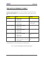
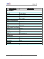
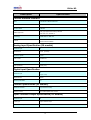
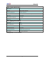
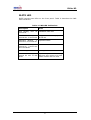
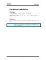
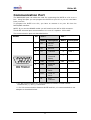
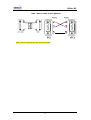
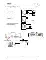
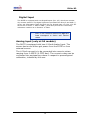
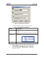
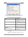
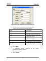
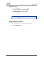
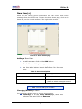
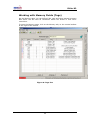
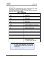
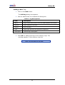
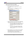
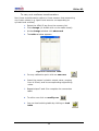
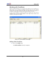
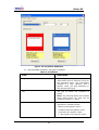
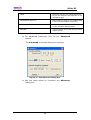
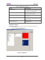
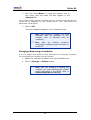
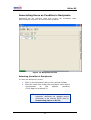
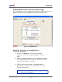
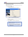
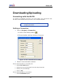
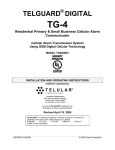
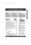
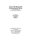
The RLITE
products
MODEL X2
User Manual
Version 3.4
26 MAY 2009
RLITE products USER MANUAL
RLite-X2
Table of Contents
INTRODUCTION ..................................................................................................................................1
RLITE LED.........................................................................................................................................6
HARDWARE INSTALLATION ..........................................................................................................7
SIM CARD ............................................................................................................................................7
ANTENNA..............................................................................................................................................7
POWER SUPPLY CABLE .....................................................................................................................11
RELAY OUTPUT ...................................................................................................................................11
DIGITAL INPUT...................................................................................................................................12
ANALOG INPUT (ONLY AT 2A MODELS).............................................................................................12
THE APPLICATION SOFTWARE ...................................................................................................13
PROJECT.............................................................................................................................................13
Creating a New Project:.................................................................................................................13
Opening a Project: .........................................................................................................................17
Viewing a Project's Properties:......................................................................................................17
NEW USER(S) .....................................................................................................................................18
Adding a New User: .......................................................................................................................18
Changing/Deleting a User: ............................................................................................................18
WORKING WITH MEMORY FIELDS (TAGS).......................................................................................20
Default Tags: ..................................................................................................................................21
Adding a New Tag:.........................................................................................................................22
Analog inputs calibration (2A models)...........................................................................................23
Linear conversion and sensor calibration (AN1): ..........................................................................23
To carry out nonlinear transformation: .........................................................................................24
Changing/Removing a Tag:............................................................................................................25
WORKING WITH CONDITIONS ...........................................................................................................26
Adding a New Condition: ..............................................................................................................26
Attaching Values: ..........................................................................................................................29
Changing/Removing a Condition: ................................................................................................30
ASSOCIATING USERS AS CONDITION’S RECIPIENTS.........................................................................31
Selecting Condition’s Recipients: .................................................................................................31
RLITE-WEB MODELS ADVANCED SETTINGS ...................................................................................32
Selecting Channels and Logging Rate:.........................................................................................32
Defining Dispatch Tasks: ..............................................................................................................33
DOWNLOADING/UPLOADING.......................................................................................................34
CONNECTING WITH THE RLITE .......................................................................................................34
Defining a Connection: .................................................................................................................34
Remote Download: ........................................................................................................................35
Setting up the Cellular Modem: ....................................................................................................35
Establishing a Connection with RLITE Unit: ..............................................................................35
Downloading a Project:.................................................................................................................36
Uploading a Project:......................................................................................................................36
USING SMS TO COMMUNICATE WITH THE RLITE................................................................37
INQUIRIES...........................................................................................................................................37
DIRECTIVES........................................................................................................................................38
CONTACT INFORMATION .............................................................................................................39
RLITE products USER MANUAL
RLite-X2
Introduction
Thank you for purchasing Remmon RLite GSM/GPRS RTU system. Please
read this guide carefully to ensure proper installation.
Remmon is committed for providing the best cellular interactive
monitoring solutions for your business. If you need further assistance,
please contact Remmon Remote Monitoring at [email protected] or
visit our web site at www.remmon.com. For all contact information, see
page 39.
Attention!
•
•
Before using this product read carefully this manual.
All examples and diagrams are intended to aid understanding,
and do not guarantee operation.
•
Remmon Remote Monitoring accepts no responsibility for
actual use of this product based on these examples.
Please dispose of this product according to local and national
standards and regulation.
Only qualified service personnel should open this device or
carry out repairs.
•
Warning: The RLITE is floating unit.
Make sure that no connection between the RLITE unit and
other electrical points.
Failure to comply with appropriate safety guidelines can cause
severe injury or property damage
Do not attempt to use this device with parameters that exceed
permissible levels.
Do not install in areas with: excessive or conductive dust, corrosive
or flammable gas, moisture or rain, excessive heat, regular impact
shock or excessive vibration.
Do not place in water or let water leak onto the unit.
Do not allow debris to fall inside the unit during installation.
1
RLite-X2
THE RLITE X2 PRODUCT FAMILY
The RLite X2 product family gives you variety of option to suit your needs, below a
table that define all products:
All models can be with one of two communication interface options: RS-232 or RS485.
MODEL
I/O
NOTES
RLITE X2
4 Digital Inputs
1 Relay Output
RLITE X2 PRO 2A
2 Analog 4-20mA inputs
2 Digital Inputs
1 Relay Output
RLITE X2 PRO 2O
2 Open Collector Outputs
2 Digital Inputs
1 Relay Output
RLITE X2 WEB 2A
*
2 Analog 4-20mA inputs
2 Digital Inputs
1 Relay Output
RLITE X2 WEB 2O
*
2 Open Collector Outputs
2 Digital Inputs
1 Relay Output
RLITE X2 WEB 2C
4 Digital Inputs
*
2 Counters connected to 2 of the DI
1 Relay Output
Two nonlinear
calibration table to both
Analog inputs
Not include nonlinear
table
The Counter increasing
with any upraise of the
DI.
Table 1: RLITE models
* The WEB option is refer to the log and server database option.
NOTE: You can see the model type at the back of your device.
2
RLite-X2
Specification
Description
HW interfaces
RS-232 / RS-485
One DB9 male (standard EIA)
Analog Inputs
See models table (page )
Digital Inputs/Output
See models table (page )
Digital Output
1 (Relay 1A at 12-24V)
Display
2 Leds (red, yellow)
Physical Characteristic
Dimension
104 X 67 X 33 mm
Weight
200 gram
Assembly
2 screw handles
Power supply Specification
Power supply
9-24VDC 1A
Active current
100mA
Stand by current
30mA
Protection
According to MIL-STD-704E
Environment
Operating Temperature
-200C to 700C
Storage Temperature
-400C to 850C
Operating Humidity
5% to 95%
Protocols
PLC protocols
MODBUS, Unitronics, Microlog, Hostlink, Izumi and more…
3
RLite-X2
Description
Specification
Cellular Network Interface
Band
Two Band/ Tri Band/ Quad band
Protocols
CSD, SMS, GPRS class 10, Mobile station class B
Internal modem
Telit 864
Fully type approved according to R&TTE
Modem Approvals
CE, GCF, FCC, PCTRB, IC
Technology
GSM network + SIM card
Internal antenna MMCX
Antenna
External antenna MMCX
Analog input Specification (2A models)
Number of input
2
Resolution bit
10 bit (0.02mA)
Conversion speed
10mS
Input Current
4-20mA DC
Precision
2% (0.4mA)
Input impedance
160Ω (10%)
Digital input Specification
4
Number of input
2 (2A or 2O)
Response time
20mS
Minimum pulse width
1s
Counter Specification (2C models)
Number of Counters
2 (connect to Di1,Di2)
Maximum counts
up to 65535 pulses each counter
Open Collector Output Specification (2O models)
Number of input
2
Output type
Open collector output
Max current thru open collector
150mA
4
RLite-X2
Relay Output Specification
Number of output
1
Output type
Relay 1A/30VDC 0.5A/125VAC
Max switching voltage/current
220VDC/1A 250VAC/1A
Contact life cycle
200,000 operations minimum (contact rating)
Minimum load
0.01mA/10mV
Contact resistance or voltage drop
up to 50mΩ
Response time
3mS
Data Logging (WEB models)
Logger Memory
20KB
Minimum Logging Interval
1 Minute
Maximum Channels Sampling
10
Transferring Data Schedule
Up to 5 tasks
Transferring Data Destination
REMMON website (private user login)
Socket definition
Compatible for DNS definition
R-LITE Approvals : CE, RoHs compatible.
5
RLite-X2
RLITE LED
RLITE contains two LEDs on the front panel. Table 2 describes the PWR
LED indications.
Table 1: PWR LED Indications
Description
Fast blinking,
second Off
State
then
20
Initialization after reset
Periodical
Blinking:
2
seconds On, ½ second Off
Empty database – No project in
RLITE unit
Periodical
Blinking:
½
second On, 2 seconds Off
Operational state
Periodical
Blinking:
1
second On, 1 second Off
and 5 fast blinks
Connection state with PC
Fast blinking
Sending SMS
Periodical
Blinking:
1
second On and 10 fast
blinks.
Pipe/Gateway state – Transferring
data from PLC device to PC with
cellular modem and vice versa.
6
RLite-X2
Hardware Installation
SIM Card
To send and receive an SMS, you need a valid SIM card.
Insert the SIM card into the SIM slot on the back panel, as shown in
Figure 1.
Antenna
Plug in the GSM antenna by connecting the MMCX plug into the ANT
socket.
Warning: The RLITE PRO is floating unit.
Make sure that no connection between the RLITE PRO unit and
other electrical points.
7
RLite-X2
Communication Port
The RS232/485 port can either be used for connecting the RLITE to a PC or to a
PLC. Using this port you can program the RLITE via your PC or you can read data
from your PLC.
To program the RLITE via a PC, you have to connect it to your PC thru the
RS232/485 interface.
NOTE: If you use the RS485 model you will need to use 485 to 232 converter.
The RLITE X2 serial port communication is in one of 2 options: 232 or 485.
The communication pins are described below.
Socket
Pin
232 **
485 *
Name
Description
Name
1
CD
Carrier
detect
2
RX
Receive
3
TX
Transmit
+
Data +
4
DTR
Data
Terminal
Ready
-
Data -
5
GND
Ground
6
DSR
Data Set
Ready
7
RTS
Request To
Send
8
CTS
Clear To
Send
9
RI
Ring
Indicator
GND
Description
Ground
* For 485 communication it's recommended to connect a 100Ω resistor
between the (+) and (-) connectors.
** For 232 communication between RLITE and PLC, it's recommended to use
adapter as described below.
8
RLite-X2
DB9 - Male to Male 3 wire Adapter:
Note: The 6 remains pins are not connected!
9
RLite-X2
Cabling the R-LITE X2 I/O
Cabling Analog inputs
Model: PRO/WEB 2A
Digital inputs cabling
All models
Cabling Open collector output
Model: PRO/WEB 2O
Back Panel Interface
Front Panel Interface
Power supply and
relay output
connector
Relay output cabling
10
RLite-X2
Table 2:RJ12 Pin out Information
Socket
Pin
MODEL
RLITE
X2(WEB)
RLITE X2- PRO(WEB)- 2A
RLITE X2- PRO(WEB)- 2O
1
NA
ANALOG +
ANALOG +
2
Din1
Analog input 1 (Ain1)
Din1
3
Din2
Analog input 2 (Ain2)
Din2
4
Din3
Digital input 1 (Din1)
Open Collector output
(OUT3)
5
Din4
Digital input 2 (Din2)
Open Collector output
(OUT2)
6
GND
Ground(-)
Warning: The RLITE X2 is floating device.
Make sure that no connection between the RLITE X2 unit and
other
electrical points.
Power Supply Cable
Plug in the power plug into the power socket, as shown in Figure 1.
Relay output
The RLite comes with one relay output. Relay output can be activated or
deactivated either by setting a predefined condition or by sending an SMS
message from a recognized mobile phone. When the Relay output is in
active state then poles A and B (at power connector, see figure) are
connected.
To use the relay output, follow these instructions:
Disconnect the power cable from both sides (power and unit)
Uncover the cable near the unit side connector.
Cut the wire that bridge between pole A and B (see figure 1)
The two wires are the two poles of the relay switch.
11
RLite-X2
Digital Input
The RLITE is equipped with two Digital Inputs (Din 1/2) which can monitor
dry contact sensors. The digital inputs are provided thru Din1/2 and GND (-)
wires, see Information Table for RJ12 pin out. Digital input 1/2 (Din 1/2) are
said to be in Active ‘1’ state if GND (-) and Din1/2 wires are connected,
otherwise it said to be in Inactive ‘0’ state.
Note: In the conditions statements, High and
Low correspond to Active and Inactive
states.
Analog input (only at 2A models)
The RLITE is equipped with two 4-20mA Analog Input. The
sensor device can either get power from the RLITE or from
external source.
The 4-20mA current is to be converted into numeric values
ranging from 0-65535 (0-FFFF Hex). The numeric value can be
converted into engineering values in respect to preconfigured
calibration, initiated by the user.
12
RLite-X2
The Application Software
Project
An RLITE project (or simply a project) is a computer file with an “rlt”
extension. The RLITE application software can either create a new project
or open an existing one. A project is the RLITE basic working environment.
It is a platform, where you can edit your settings and download them to
the RLITE. When the project is set it can be downloaded to the RLITE, thus
configuring the RLITE behavior.
Creating a New Project:
To create a new project:
1. Click on File>New
or click on the New project button
The New project dialog box appears.
Figure 1: New Project
2. In the name textbox, type in a name for your
project, choose a directory path and click on Next.
The Unit Definition dialog box appears.
13
RLite-X2
Figure 2: Unit Definition dialog-box
3. Fill in the fields as described in the following table.
Table 2: Unit Definition Descriptions
Field
Description
Unit Model
Click on the down-drop-list to select your RLITE
model.
Use table 1:"RLITE models" and the label at the back of your
device
Unit phone
Insert the unit phone number as ascribed to the SIM
card in use.
Description
Note: To configure the
RLITE unit via cellular
modem, you must
provide a valid phone
number.
Free text, describing your project.
4. Click on Next. If the unit model is RLITE-Web then
Communication settings dialog box appears. If
not then PLC and Communication Protocols
dialog box appears.
14
RLite-X2
Figure 3: Communication Settings dialog box (only at Web models)
5. Fill in the fields, as described in the following table.
Table 3: Communication Settings Field Descriptions
Field
Description
APN context
Connection string supplied by the
cellular provider of the SIM card. The
string must start and finish with
quotation marks.
User name
Username supplied by the cellular
provider of the SIM card. The string
must start and finish with quotation
marks.
Password
Password supplied by the cellular
provider of the SIM card. The string
must start and finish with quotation
marks.
Server socket
Connection string supplied by your
supplier. The string must start with
the Socket number and then the IP
string started and finished with
quotation marks.
[Default:
55123,"m2m.remmon.com"]
6. Click on Next.
The PLC and Communication Protocols dialog box
appears.
15
RLite-X2
Figure 4: PLC and Communication Protocol dialog box
7. Fill in the fields, as described in the following table.
Table 4: PLC and Protocol Field Descriptions
Field
Description
PLC Type
Select PLC protocol
Scan period
Select the period of time between the
PLC's data scans by the RLITE unit
Baud
Select baud rate for communication
protocol with the PLC
Parity
Select Parity bit for communication
protocol with the PLC
DataLen
Select
Data
length(Bits)
for
communication protocol with the PLC
StopBits
Select Stop Bit for communication
protocol with the PLC
8. Click on Next.
A confirmation window, summing
configuration settings, appears.
9. Review your settings
10. Click on Finish.
16
all
the
project
RLite-X2
Opening a Project:
1. Click on File>Open
or click on the Open project button
The Open project dialog-box appears.
2. Browse to the project directory, select your project
and click on Open.
Note: To reopen a project, go to the menu bar and click on
File>"project name".
Viewing a Project's Properties:
To view your project properties:
1. On the menu bar, click on Project>Properties.
2. Click on Next >Finish.
17
RLite-X2
New User(s)
Users are the cellular phone subscribers who can control and receive
messages from the RLITE unit. To open the Users sheet page, click on the
Users tab, on the vertical toolbar on the right of the screen.
Figure 5: Users sheet page
Adding a New User:
1. To add new user click on the Add button.
The Add user dialog-box appears
2. Use the table below to set definitions for the new
user.
Table 5: User Descriptions
Field
Description
User name
The name of the user
User Phone
The phone number of the cellular
phone to which messages are sent
3. Click OK.
Note: You can add up to 16 users
Changing/Deleting a User:
You can either delete a user or change its properties.
Deleting: Go to the Users sheet page, select the
relevant user and click on Remove.
18
RLite-X2
Changing: Go to the Users sheet page, click on
Change. In the Modify user dialog box, change
the user name or phone.
19
RLite-X2
Working with Memory Fields (Tags)
On the Memory page you can define I/Os, tags and other general purpose
Bits which can be used as conditions within the RLITE or with other
controllers.
To open the Memory page, click on the Memory tab, on the vertical toolbar
at the right of the screen.
Figure 6: Tags List
20
RLite-X2
Default Tags:
The Memory tab contains default tag names, assigning tags to the RLITE
specifications, as described in the table below for model X2.
The default Tags will appear according to your unit model that had chosen
at the unit definition dialog box (page )
Table 6: Default Tags
Tag
Description
Din1
Digital input 1
Din2
Digital input 2
Din3
Digital input 3
Din4
Digital input 4
AN1
Analog input 1
AN2
Analog input 2
VOL1
Nonlinear calibration for analog input 1
VOL2
Nonlinear calibration for analog input 2
C1
Counter 1 connect to Din1
C2
Counter 2 connect to Din2
OUT2
Open collector output 1
OUT3
Open collector output 2
OUT1
Relay output
Time
Time register
Date
Date register
DayOfWeek
Day of the week register
PLC_COMM
Communication regularity status: '0' for
communication in order.
'1' for communication abnormal
Note: Make sure that your PC time and date clock
is correct. When downloading, the RLITE clock
automatically synchronized with your computer time
and date clock.
Also the RLite take clock from the cellular network
any time the unit powered on.
21
RLite-X2
Adding a New Tag:
1. Click on the Add button.
The Add tag dialog-box appears.
2. Use the table below to complete the dialog-box.
Table 7: Tag Descriptions
Field
Description
Name
Tag's name which will be used for SMS feedback and reports
Address
Tag's address in the PLC
Station
PLC's Number
Type
Tag's type derived from protocol's properties
Description
General tag's description
3. Click OK for adding this tag to the memory map. The
new tag appears in the memory map list.
Note: You can add up to 100 tags.
22
RLite-X2
Analog inputs calibration (2A models)
Linear conversion and sensor calibration (AN1):
1. Select the AN1/2 tag from the memory list.
2. Click change button (or double click on the table
sheet).
3. At the change window click advanced button (at the
bottom right side).
4. The advanced calibration window appears.
Figure 7: Advance Calibration
5. The linear conversion is to be determined by mapping two
different engineering values, one to the lower electric value
(4 mA) and one to the upper electric value (20mA).
6.
1.
At the upper textbox, insert engineering value. This
value is to be mapped to the lower electric value
(e.g. connecting sensor that 4ma goes to -20C,
type -20).
2.
At the lower textbox, insert engineering value.
This value is to be mapped to the upper electric
value (e.g. connecting sensor that 20ma goes to
100bar, type 100).
While connected to unit, you can fine tune your calibration
online by adjusting your linear conversion. The Current
value display-box shows the current engineering value
online with respect to your linear conversion.
The new calibration takes effect after Data download.
23
RLite-X2
To carry out nonlinear transformation:
Non Linear transformation refers to linear sensors that measuring
non-linear values (e.g. liquid level sensors corresponding to
cylinder tank volume)
1. Select the VOL1/2 tag from the memory list.
2. Click change (or double click on the table sheet).
3. At the change window click advanced
4. The table window appears.
Figure 8: Conversion Table
5. For any calibration point click on new row
6. Insert the sensor’s electric output value, ranging
from 4-20mA, and its corresponding engineering
value.
7. Repeat steps 5 and 6 to complete the conversion
table.
8. To edit a row click on modify row
9. You can load existing table by clicking on load
table
24
RLite-X2
Changing/Removing a Tag:
10. Select the relevant Tag from the memory list.
11. Click Change or Remove button.
Note: You cannot change or remove a
system's default tags.
After you define, add or remove new tag,
download the updated project information to
the RLITE unit (refer to Downloading or
uploading a project)
25
RLite-X2
Working with Conditions
Setting conditions allows you to configure the behavior of your RLITE on a
given event. It is a logical mechanism through which you can specify
events that will trigger sending an SMS. You also specify the recipient of
the SMS, if output relay is going to be opened/closed, and more.
To set a new condition, as well as modify an existing one click on the
Conditions tab, on the vertical toolbar on the right of the screen. The
Condition sheet page will appear.
Figure 9 : The Condition sheet page
Adding a New Condition:
12. Click on the Add button
the Add condition dialog box appears.
26
RLite-X2
Figure 10: Condition Definition
13. Use the table below to set your condition.
Table 8: Conditions
Field
Description
Logical condition
The
logical
expression,
which
determines when a warning is sent to
the specified users. The expression
consists of a Tag, operator, and a
specific value (its type depends on
the selected I/O type).
I/O
The I/O on which the condition is
based.
Note: The I/O drop down list contains
some other items you may use as
condition’s base (i.e.-time).
Operator
The operator of the logical
expression. Possible values:
=Equal to the specific value.
> Greater than the specific value.
< Less than the specific value.
<> Not equal to the specific value.
27
RLite-X2
Value
Select the value in the logical expression,
its type and selection form depends on the
selected I/O type
Send SMS on alarm On
Select SMS on alarm on for sending SMS
in case of event/condition occurrence
Send SMS on alarm Off
Select SMS on alarm off for sending SMS
in case of event's status inversion.
SMS text
Type text that is sent to the specified users
cellular phones.
14. For advanced properties click on the Advanced
button.
The Advanced properties dialog-box appears.
Figure 11: The Advanced dialog-box
15. Use the table below to complete the Advanced
dialog-box.
28
RLite-X2
Table 9: Advanced Properties
Field
Description
Stability time
The amount of time during which the
condition’s logical expression must be
'true' before an SMS is sent.
Send it: xx times
The number of times the message will
be sent to each recipient.
Every :xx:xx
The time passed between sending the
messages.
Out 1
Relay output activation by condition:
Open for open relay contact. Close for
relay contact.
Wait stability time
Mark this option in order to wait
stability time.
Attaching Values:
To select any additional value(s) to be sent to your cellular phone with the
text for this condition:
1. Click on the Attach Values tab
Figure 12: SMS Report
29
RLite-X2
2. Click the value Name. A mark will appear next to
the value, and the value will also appear in the
Selected list.
The Cellular screen window simulates how the condition message with its
values will be displayed on your cellular phone. (The ### marks the
parameters value digits).
3. Click on OK.
The new condition appears in the Conditions List.
Note: After defining a condition, you must
associate users as recipients for the
condition (refer to Associate users as
conditions).
Note: After you defining conditions,
download the updated project information to
the RLITE.
Changing/Removing a Condition:
If you no longer want RLITE to send warnings for a particular condition,
you can delete the condition from the project.
1. Select the relevant condition from the Conditions list.
2. Click on Change or Delete button.
Note: After you changing or deleting any
condition, you must download the updated
project information to the RLITE (refer to
Downloading Data to an RLITE).
30
RLite-X2
Associating Users as Condition’s Recipients
Recipients are the selected users that receive the conditions' SMS.
Each condition may have its own selected recipients.
Figure 13: Recipients Screen
Selecting Condition’s Recipients:
To reach the Recipient's screen,
3. Click on the Recipient's tab on the vertical toolbar.
4. Click the check box under the recipient's name which
corresponds
to
the
specific
condition
(Click again to uncheck it)
Note: After you select a condition’s
recipients, download the updated project
information to the relevant RLITE (refer to
Downloading Data to an RLITE).
31
RLite-X2
RLITE-Web models Advanced Settings
The Web tab allows you to configure the sample rate, the channels to be
logged, and the interval to dispatch the data into the web server.
Figure 14: Web Screen
Selecting Channels and Logging Rate:
To reach the Web screen,
1.
Click on the Web tab on the vertical toolbar
(appears only if the project belongs to the Web
type).
2.
Select the logging rate using the up/down buttons in
the Logging Definitions box at the top of the screen.
The minimum rate is 1 minute.
3.
Click on the channel name to be logged at the
RLITE-Web. To deselect the channel, click on the
channel name again.
Note: The RLITE-Web supports only 10
channels to be logged.
32
RLite-X2
Defining Dispatch Tasks:
Dispatch task is a periodical event for sending data to the web server.
To define a Dispatch task,
1.
Click on the Add button.
The Scheduled Tasks dialog box appears.
Figure 15: Scheduled Tasks dialog box
2.
Select the task performing periodicity and follow the
on-screen instructions.
3.
Click on Finish to complete the task setting.
Note: The RLITE-Web models supports up to
five scheduled tasks.
Note: Confirm that the RLITE-Web date and
time are accurate, because the Scheduled
Tasks feature relies on this information to run
scheduled tasks.
33
RLite-X2
Downloading/Uploading
Connecting with the RLITE
To upload or download a project, you must define your connection with
the unit via the serial port of your PC or via a cellular modem.
Note: Ensure that the RLITE hardware is
properly connected
Defining a Connection:
1. Click on Project > Connection
or click on the Setting button
A Communication settings window will pop up
Figure 16: PC Communication settings
2. Select a communication method.
If the communication is via serial port:
•
Select Via serial option
•
Select the correct serial port from the drop-down box
•
Select your port settings
•
Click on OK
If the communication is via modem:
•
Select Via Modem option
34
RLite-X2
•
Select Modem from the drop-down box
•
Click on OK
Remote Download:
To support communication between RLITE software and the RLITE unit, a
cellular modem needs to be connected to the PC that is running RLITE
software.
Note: Ensure that both the RLITE’s SIM and
the PC’s modem’s SIM cards support CSD
communication.
Note: If the RLITE’s SIM and the PC
modem’s SIM are from different cellular
service providers, use the DATA-IN number
(the phone number for using the CSD) as
the RLITE number in the RLITEs list on the
Project
Main
screen.
Your cellular service provider should
enable the SIM cards for CSD, and inform
you of their DATA-IN number.
Setting up the Cellular Modem:
Before installing the cellular modem in your PC, insert the SIM card into
the modem so that the modem can transmit and receive data via the
cellular network. For instructions regarding installation of the SIM card,
refer to the modem’s documentation. The modem is connected to the PC
with a 9 pin D-shell cable.
To connect the modem to the PC:
1. Connect the female end of the 9 pin D-shell cable to
the PC that is running RLITE SOFTWARE
2. Connect the male end of the cable to the cellular
modem.
Establishing a Connection with RLITE Unit:
1. Click on the Users tab on the vertical toolbar to
open the Users List screen.
2. Enter your password.
Note: For the initial connection to the RLITE
unit, enter the default password: 000000
(six zeros)
3. Click the Connect button
35
RLite-X2
4. Wait a few seconds. A green RUN indicator on the
bottom left- of the screen will confirm your
connection.
Note: After establishing connection, you can
change the password by typing a new six
letter password and clicking on the Change
password button
Downloading a Project:
After designing a project you must download the project to the RLITE unit.
Note: Before downloading a project, make
sure you have established a connection with
the RLITE unit.
1. Click the Download button
2. Wait a few seconds till the download process is
completed.
Note: After making changes to the project, it
must be downloaded to the RLITE unit to
become valid.
Uploading a Project:
Warning: Uploading data prom the RLITE
unit to an open project will erase all previous
data on that project!!!
In order to upload a project from the RLITE unit you must open a project.
1. Click New project or open an existing one.
2. Click Upload button
3. Wait a few seconds till the upload process is
completed.
36
RLite-X2
Using SMS to communicate with
the RLITE
After a successful download you can put the RLITE into work. Only
users, which had been defined in the RLITE configuration settings,
can communicate with the RLITE. A typical RLITE user can either
get warning SMS messages from the RLITE or send inquiry/directive
SMS messages to the RLITE.
Inquiries
With the RLITE in the field, you can check for the current value of
each of its Tags. Each user, defined in the RLITE configuration, can
send an inquiry SMS message with the following format:
?<Tag's name>,
Note: You may concatenate in one SMS, more
than one request in the following format.
? <tag name-1>,<tag name-2>,
Examples:
To get the current time of the RLITE, send an SMS message to the RLITE
SIM card number with the following text:
?Time,
To get the time and date of the RLITE, send an SMS message with the
following ftext:
?Time,Date,
To get the current value of digital input 1, send an SMS message with the
following format:
?<the name of digital input 1>,
The default name for digital input 1 Tag is Din1; during RLITE
configuration one may rename some or all of the Tags. If the default name
of digital input 1 hasn't been renamed, then a user may get its current
value by sending an SMS message with the following text:
?Din1,
Note: The Header in SMS must be exactly like the header as
configured at software, include capital letters if there is.
37
RLite-X2
Directives
With the RLITE in the field, you can change or reset each of its Tags. Each
user, defined in the RLITE configuration settings, can send a directive SMS
message with the following format:
!<tag's name>=<value>,
Note: After RLITE sets the new value, a
notification message is sent to your cellular
phone.
Note: You may concatenate in one SMS, more
than one set command in the following format.
!<Text-1>=<value-1>,<Text-2>=<value-2>,
Examples:
To set the RLITE time to a specific hour, a user can send an SMS message
to the RLITE SIM card number with the following format:
!Time=HH:MM,
To set the time to 16:30 the user should send SMS message to the RLITE
Sim card number containing the following text:
!Time=16:30
To set the RLITE date to a specific date, a user can send an SMS message
to the RLITE SIM card number with the following format:
!Date=dd.mm.yy,
To set the date to August 11 2007 one should write
!Date=11.08.07,
If it is now August 11 2007 and the time is 16:30, then one can set the
time and date by sending the following SMS text:
!Time=16:30,date=11.08.07,
To turn on the output relay, send an SMS message with the following
format:
!<the name of the relay output>=1,
The default name for the output relay Tag is Out; during RLITE
configuration one may want to rename some or all of the Tags. If the
default name of the relay output hasn't been changed, then one may turn
it on by sending the following SMS text:
!OUT=1,
Alternatively, to turn off the relay output send the following SMS text:
!OUT=0,
38
RLite-X2
Contact Information
Address:
Industrial Area – Beit She'an, Israel, 10800
Email: [email protected]
Phone: 972-4-6065815
Fax:
972-4-6065819
Website:
www.remmon.com
39