1
Omron CIP Ethernet/IP
Communication Server
for Microsoft Windows
and Wonderware Applications
User Manual
Ver 1.x Rev 1.1
DR 600 10
DR 600 11
KLINKMANN AUTOMATION
P.O. Box 38
FIN-00371 Helsinki Finland
Tel. int. + 358 9 5404940
Fax int. + 358 9 5413541
www.klinkmann.com
Omron CIP Communication Server
i
Table Of Contents
Overview ......................................................................................................................... 1
Communication Protocols ............................................................................................... 2
Accessing Remote Items via the Server.......................................................................... 3
Installing the OmronCIP Server ....................................................................................... 4
Installing the Server .................................................................................................... 4
Licensing by using HASP HL key................................................................................ 7
Software license key ................................................................................................... 7
Transferring the software license to other computer ............................................... 8
Configuring the OmronCIP Server .................................................................................. 11
Server Settings Command .......................................................................................... 11
Socket Definition Command........................................................................................ 12
Saving OmronCIP Configuration File .......................................................................... 13
Configuration File Location ......................................................................................... 14
Topic Definition Command .......................................................................................... 14
Item Names ..................................................................................................................... 16
Monitoring and Controlling Communication with a PLC .............................................. 17
Using the OmronCIP Server with Suite Link and DDE Clients ........................................ 20
Using the OmronCIP Server with InTouch .................................................................. 20
Defining the Access Names .................................................................................... 20
Defining the Tagnames ........................................................................................... 23
Monitoring the Status of Communication with InTouch ........................................... 25
Notes on Using Microsoft Excel .................................................................................. 25
Reading Values into Excel Spreadsheets ............................................................... 25
Writing Values to OmronCIP Points ........................................................................ 25
Using the OmronCIP Server with OPC Clients ................................................................ 27
Configuring DCOM ...................................................................................................... 27
Firewall ................................................................................................................... 27
OmronCIP OPC Server settings ............................................................................. 28
OPCEnum settings ................................................................................................. 30
OPC Client side settings ......................................................................................... 31
Running OmronCIP “OPC & DDE” version as Windows Service ................................ 33
Troubleshooting .............................................................................................................. 34
WIN.INI entries............................................................................................................ 34
Troubleshooting menu ................................................................................................ 36
Internal Logger ............................................................................................................ 37
Omron CIP Communication Server Ver 1.x User Manual Rev 1.1
6001xm11
Omron CIP Communication Server
1
Omron CIP Ethernet/IP
Communication Server
Overview
The Omron CIP Ethernet/IP Communication Server (hereafter referred to as the
“Omron CIP Server” or “OmronCIP” or “Server”) is a Microsoft Windows 32-bit application
program that acts as a communication protocol server and allows other Windows
programs to access to data from Omron SYSMAC NJ-series Controllers using the
Ethernet/IP CIP (Common Industrial Protocol) Message Communications (Ethernet/IP
explicit messaging).
Omron CIP Server uses Connection based Explicit Messages to read and write NJ-series
Controller Global Variables, without adding any special programming to the Controller
program. Message type - CIP class 3 connection messages (Large_Forward_Open
Service). The Global Variables definition file exported from Omron Sysmac Studio
programming software is used by Omron CIP Server to validate the item names and their
properties.
Any Microsoft Windows program that is capable of acting as a DDE, FastDDE, SuiteLink
or OPC Client may use the OmronCIP Server.
There are two different OmronCIP Server versions described in this manual:
- Server version (ordering number DR 600 10), supporting SuiteLink, FastDDE and
DDE protocols; this version hereafter is referred to as the “Suite Link & DDE” version.
- Server version (ordering number DR 600 11), supporting OPC and DDE protocols; this
version hereafter is referred to as the “OPC & DDE” version;
The separate installation package is supplied for each version of the Server. In both
cases, the name of Server executable file is OmronCIP.EXE. All further information in
this manual is same for all versions of the Server, with the exception of few points where
communication protocol specific features are explained.
Omron CIP Communication Server Ver 1.x User Manual Rev 1.1
6001xm11
Omron CIP Communication Server
2
Communication Protocols
Dynamic Data Exchange (DDE) is a communication protocol developed by Microsoft to
allow applications in the Windows environment to send/receive data and instructions
to/from each other. It implements a client-server relationship between two concurrently
running applications. The server application provides the data and accepts requests from
any other application interested in its data. Requesting applications are called clients.
Some applications such as Wonderware InTouch and Microsoft Excel can simultaneously
be both a client and a server.
FastDDE provides a means of packing many proprietary Wonderware DDE messages
into a single Microsoft DDE message. This packing improves efficiency and performance
by reducing the total number of DDE transactions required between a client and a server.
Although Wonderware's FastDDE has extended the usefulness of DDE for the industry,
this extension is being pushed to its performance constraints in distributed environments.
The OmronCIP Server “Suite Link & DDE version” supports the FastDDE Version 3 - an
extension to Wonderware’s proprietary FastDDE Version 2. This extension supports the
transfer of Value Time Quality (VTQ) information. The original DDE and FastDDE Version
2 formats are still supported, providing full backward compatibility with older DDE clients.
FastDDE Version 3 works on Windows 9x systems as well as Windows NT systems.
NetDDE extends the standard Windows DDE functionality to include communication over
local area networks and through serial ports. Network extensions are available to allow
DDE links between applications running on different computers connected via networks or
modems. For example, NetDDE supports DDE between applications running on IBM
compatible computers connected via LAN or modem and DDE-aware applications
running on non-PC based platforms under operating environments such as VMS and
UNIX.
SuiteLink uses a TCP/IP based protocol and is designed by Wonderware specifically to
meet industrial needs such as data integrity, high-throughput, and easier diagnostics. This
protocol standard is only supported on Microsoft Windows NT 4.0 or higher. SuiteLink is
not a replacement for DDE, FastDDE, or NetDDE. The protocol used between a client
and a server depends on your network connections and configurations. SuiteLink was
designed to be the industrial data network distribution standard and provides the following
features:
· Value Time Quality (VTQ) places a time stamp and quality indicator on all data values
delivered to VTQ-aware clients.
· Extensive diagnostics of the data throughput, server loading, computer resource
consumption, and network transport are made accessible through the Microsoft Windows
NT operating system Performance Monitor. This feature is critical for the scheme and
maintenance of distributed industrial networks.
· Consistent high data volumes can be maintained between applications regardless if the
applications are on a single node or distributed over a large node count.
· The network transport protocol is TCP/IP using Microsoft’s standard WinSock interface.
OPC (OLE for Process Control) is an open interface standard to provide data from a data
source and communicate the data to any client application in a common standard way.
Omron CIP Communication Server Ver 1.x User Manual Rev 1.1
6001xm11
Omron CIP Communication Server
3
The OPC is based on Microsoft OLE, COM and DCOM technologies and enables simple
and standardised data interchange between the industrial or office sector and the
production sector. From general point of view many aspects of OPC are similar to DDE,
but main difference is in the implementation by using Microsoft's COM (Component
Object Model) technology. It enables fast exchange with process automation data and
OPC open interface allows access to data from OPC Server in same standard way from
OPC client applications supplied by different developers.
For more information on the basics of OPC, please refer to the OPC Specification. The
OPC Data Access Custom Interface Specification is maintained by OPC Foundation.
The OPC support for OmronCIP Server “OPC & DDE” version is implemented based on
FactorySoft OPC Server Development Toolkit and it conforms to OPC Data Access
Custom Interface Specification 2.05.
The Suite Link, FastDDE (Version 3) and DDE support for OmronCIP Server “Suite Link &
DDE” version is implemented by Wonderware I/O Server Toolkit ver. 7.2.1.6.
The FastDDE (Version 2) and DDE support for OmronCIP Server “OPC & DDE” version
is implemented by Wonderware I/O Server Toolkit ver. 5.0 (008).
The OmronCIP Server connects to Omron SYSMAC NJ-series Controllers across an
Ethernet/IP network using the Common Industrial Protocol (CIP). The EtherNet/IP is
an industrial networking standard, maintained and distributed by ODVA
(http://www.odva.org), and it is an Ethernet adaptation of CIP. The Common Industrial
Protocol (CIP) is a media-independent common application-layer industrial protocol for
industrial automation applications, providing a unified communication architecture
throughout the manufacturing enterprise.
Accessing Remote Items via the Server
The communication protocol addresses an element of data in a conversation that uses a
three-part naming convention that includes the application name, topic name and item
name. The following briefly describes each portion of this naming convention:
application name
The name of the Windows program (Server) that will be accessing the data element. In
the case of data coming from or going to Omron SYSMAC NJ-series Controller via this
Server, the application portion of the address is OmronCIP.
topic name
Meaningful names are configured in the Server to identify specific devices. These names
are then used as the topic name in all conversations to that device. For example, PLC1.
Note! You can define multiple topic names for the same device (PLC) to poll different
items at different rates.
item name
A specific data element within the specified topic. For example, when using this Server,
items can be Global Variables (Booleans, Integers, Reals (floating point), Strings,
members of Arrays and Structures, etc.) in the Omron NJ-series Controller. The term
Omron CIP Communication Server Ver 1.x User Manual Rev 1.1
6001xm11
Omron CIP Communication Server
4
"point" is used interchangeably with the term "item" in this User Manual. For more
information on item names, see the Item Names section later in this manual. The Global
Variables definition file exported from Omron Sysmac Studio programming software is
used by Omron CIP Server to validate the item names and their properties.
Installing the OmronCIP Server
Installing the Server
The OmronCIP Server installation package is supplied as a Microsoft Installer file
DR60010_xxx.msi (for “Suite Link & DDE” version) or DR60011_xxx.msi (for “OPC & DDE”
version), where xxx is the current (latest) version of OmronCIP Server.
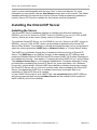
To install the OmronCIP Server, run the DR60010_xxx.msi (“Suite Link & DDE” version) or
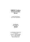
DR60011_xxx.msi (“OPC & DDE” version) and proceed as directed by the OmronCIP
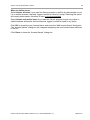
Server Setup Wizard. The installation is simple and straightforward, only it is important to
select the correct protection (HASP key or software license) in “Custom Setup” dialog:
The HASP key or Software license key is needed for full time running of OmronCIP
Server. The HASP key is an USB key (dongle) to be installed into PC USB port and
needs the SafeNet Sentinel LDK Run-time Environment (HASP HL Runtime Package) to
be installed and running – see details in “Licensing by using HASP HL key” section below.
The software license key is a 16-character alphanumeric “computer-dependent” string,
provided after purchasing the OmronCIP Server (for more information, see “Software
license key” section below. Without HASP key installed or software license key entered,
the OmronCIP Server will run one hour in demo mode. After purchasing the OmronCIP
Server, the appropriate HASP key or software license key is provided and no reinstallation of OmronCIP Server is needed.
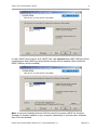
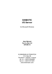
In case “HASP Device driver” and “HASP Files” are not selected then HASP USB key
will not be supported and only the software license will be available (files needed for
HASP USB key will not be installed):
Omron CIP Communication Server Ver 1.x User Manual Rev 1.1
6001xm11
Omron CIP Communication Server
5
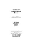
In case “HASP Device driver” and “HASP Files” are selected then HASP USB key will be
supported and both HASP-key and software license will be available (files needed for
HASP USB key will be installed):
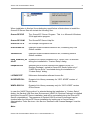
Note: In case the SafeNet Sentinel LDK Run-time Environment (HASP HL Runtime
Package) is already installed on your computer (separately or by some other software)
then it can be disabled:
Omron CIP Communication Server Ver 1.x User Manual Rev 1.1
6001xm11
Omron CIP Communication Server
6
When installation is finished, the subdirectory specified as a folder where to install the
OmronCIP Server files will contain the following files:
OmronCIP.EXE
The OmronCIP Server Program. This is a Microsoft Windows
32-bit application program.
OmronCIP.CHM
The OmronCIP Server Help file.
OmronCIP.CFG
An example configuration file.
OneVariable.txt
Example Global Variables definition file, conatining only one
Global variable.
Variables.txt
Example Global Variables definition file, conatining several
Global variables.
hasp_windows_44
42.dll
Dynamic Link Library installed only if “HASP Files” is selected
during the installation in “Custom Setup” dialog.
haspdinst.exe
Sentinel LDK Run-time Environment Installer (HASP HL
Runtime Package), copied to OmronCIP Server folder only if
“HASP Device driver” is selected during the installation in
“Custom Setup” dialog.
LICENSE.RTF
Klinkmann Automation software license file.
KLSERVER.DLL
Dynamic Link Library necessary for “OPC & DDE” version of
the Server.
WWDLG32.DLL
Dynamic Link Library necessary only for “OPC & DDE” version
Of the Server.
In case the “HASP Device driver” is selected during the installation in “Custom Setup”
dialog, the Sentinel LDK Run-time Environment (HASP HL Runtime Package) is installed
during the OmronCIP Server installation (and will be uninstalled during the OmronCIP
Server uninstallation). The presence of Sentinel LDK Run-time Environment can be
checked after the OmronCIP Server installation by looking-up in Control Panel /
Administrative Tools Services – the Service “Sentinel Local License Manager” must be
started.
Note:
Omron CIP Communication Server Ver 1.x User Manual Rev 1.1
6001xm11
Omron CIP Communication Server
7
The OmronCIP Server “Suite Link & DDE” version requires some Wonderware software
(e.g. Wonderware InTouch) is installed on same computer. For “non-Wonderware”
systems use the OmronCIP Server “OPC & DDE” version.
To uninstall the OmronCIP Server, start Control Panel, select “Uninstall a program” and
select the “OmronCIP SuiteLink and DDE Server” or “OmronCIP OPC and DDE Server”
from the list of available software products. Click on “Uninstall” and proceed as directed
by the Uninstall Wizard.
Licensing by using HASP HL key
The following should be done to enable the licensing by HASP HL key:
-
-
-
The “HASP Device driver” and “HASP Files” are selected during the OmronCIP
Server installation in “Custom Setup” dialog – that causes correspondingly
haspdinst.exe and hasp_windows_4442.dll files are copied to OmronCIP Server
folder and Sentinel LDK Run-time Environment (HASP HL Runtime Package) is
installed and started, enabling the OmronCIP Server can detect the HASP HL USB
dongle;
insert the received HASP key into USB port, and wait until “Installing device driver
software” message disappears and “Device driver software installed successfully”
message appears;
start OmronCIP Server and check - if “Sofware key or HASP HL key not found!”
message does not appear then it means everything is done correctly and
OmronCIP Server runs in full mode with licensing by HASP HL key enabled.
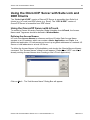
Software license key
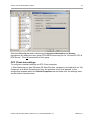
OmronCIP Server supports the “computer dependent” software licensing. The following
steps are required to enable it:
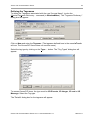
1) Start OmronCIP Server, click on "Help" menu item (also short-cut Alt+H can be used)
and pop-up menu with "Help" menu commands will appear:
Select “License” and “License” dialog will appear:
Omron CIP Communication Server Ver 1.x User Manual Rev 1.1
6001xm11
Omron CIP Communication Server
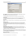
8
2) Here the “Customer PC Code” is “computer-dependent” string generated by OmronCIP
Server and it is unique for this computer. Write it down or Copy/Paste to e-mail when
ordering the OmronCIP Server.
3) After purchasing the OmronCIP Server, you will get the software license key - 16character alphanumeric string. Open the “License” dialog again and Copy/Paste it to
“Software Key” field:
4) Click OK and restart OmronCIP Server. OmronCIP Server software license now is
enabled.
Note – the “Software Key” string is saved to MS Windows system directory (e.g.
C:\Windows) WIN.INI file [OmronCIP] section to enable it is automatically detected at
OmronCIP Server next start-up.
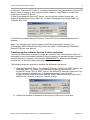
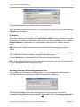
Transferring the software license to other computer
The transfer of Software License Key might be needed in very rare situations when it is
necessary to move Klinkmann software to other computer (or operation system change is
planned for same computer). Such transfer PERMANENTLY removes the Software
License Key, so be very careful when deciding to use this option.
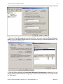
The following steps are required to transfer the Software License Key:
1) Start the OmronCIP Server. For OmronCIP Server “Suite Link & DDE” version, the
ArchestrA SMC Log Viewer (or Wonderware Logger) must be started. For
OmronCIP Server “OPC & DDE” version, the OmronCIP Internal Logger and “Log
to File” should be enabled (see “Troubleshooting menu” and “Internal
Logger”sections at the end of this manual). Select Help/License from main menu
and click the “Transfer” button on “License” dialog:
2) Confirm the transfer of Software License Key by clicking on Yes button:
Omron CIP Communication Server Ver 1.x User Manual Rev 1.1
6001xm11
Omron CIP Communication Server
9
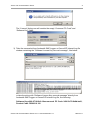
The “License” dialog now will contain the empty “Customer PC Code” and
“Software Key” fields:
3) Take the screenshot from ArchestrA SMC Logger or OmronCIP Internal Log file
window containing the “Software License Key removal message”, like below:
or take the string with “Software License Key removal message” directly from
ArchestrA SMC Logger or OmronCIP Internal Log file, like following:
Software Key e666-2719-8fe0-18aa removed. PC Code: 2496-5c75-8b8b-ba91,
Product Code: DR60010 100
Omron CIP Communication Server Ver 1.x User Manual Rev 1.1
6001xm11
Omron CIP Communication Server
10
4) Provide the obtained “Software License Key removal message” screenshot or
string together with new “Customer PC Code” when applying for new Software
License Key without purchasing the new license (in situations when it is necessary
to move Klinkmann software to other computer or operation system change is
planned).
Note!
Without providing the “Software License Key removal message” screenshot or string, the
new Software License Key will not be assigned.
Omron CIP Communication Server Ver 1.x User Manual Rev 1.1
6001xm11
Omron CIP Communication Server
11
Configuring the OmronCIP Server
After the OmronCIP Server is initially installed, a small amount of configuration is
required. Configuring the Server automatically creates a OmronCIP.CFG file that holds
all of the topic definitions entered, as well as the communication port configurations. This
file will automatically be placed in the same directory in which OmronCIP.EXE is located
unless the path where the configuration file will be placed is specified via the
/Configure/Server Settings... command.
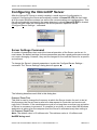
Server Settings Command
A number of parameters that control the internal operation of the Server can be set. In
most cases, the default settings for these parameters provide a good performance and do
not require changing. However, they can be changed to fine-tune the Server for a specific
environment.
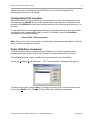
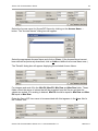
To change the Server's internal parameters, invoke the Configure/Server Settings...
command. The "Server Settings" dialog box will appear:
The following describes each field in this dialog box:
Protocol Timer Tick
This field is used to change the frequency at which the Server checks for work to do (at
this frequency the Server tries to send one data request to Controller and receive one
reply from Controller. If the send/response cycle is too long then more than one activation
of Server is necessary to process it. If computer is very busy or some other MS Windows
application is taking over the computer then the Server is activated rarely than setting in
the Protocol Timer Tick.
Note: The default value is 50 milliseconds. The minimum value is 10 milliseconds.
NetDDE being used
Omron CIP Communication Server Ver 1.x User Manual Rev 1.1
6001xm11
Omron CIP Communication Server
12
This option is disabled and not supported by OmronCIP Server.
Retry failed write messages indefinitely
This field is used to disable the deleting of pending write messages when slow poll mode
on some topic is started. As default all write messages for this topic are deleted when
topic enters the slow poll mode.
Note. Be careful when using this setting if Controller is switched off or disconncted, but
client application continues to generate new values to be written to this Controller - that
can cause the computer memory overload with memory allocated for write messages.
Configuration File Directory
This field is used to specify the path (disk drive and directory) in which OmronCIP will
save its current configuration file. The OmronCIP Server will use this path to load the
configuration file the next time it is started.
Note: Only the "path" may be modified with this field. The configuration file is always
named OmronCIP.CFG.
Note: There is no limit to the number of configuration files created, although each must
be in a separate directory. When using the OmronCIP Server with InTouch, it is good
practice to place the configuration file in the InTouch application directory.
Start automatically as Windows NT Service
This option is disabled and not supported by OmronCIP Server.
Once all entries have been made, click on OK.
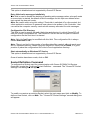
Socket Definition Command
To configure the Socket used for communication with Omron SYSMAC NJ-Servies
Controller, invoke the /Configure/Socket Definition... command. The "OmronCIP Socket
Settings" first dialog box will appear:
To modify or examine an existing Socket, select the topic name and click on Modify. To
define a new Socket, click on New. The " OmronCIP Socket Settings" second dialog box
will appear:
Omron CIP Communication Server Ver 1.x User Manual Rev 1.1
6001xm11
Omron CIP Communication Server
13
The following describes each dialog field in this dialog box:
Socket Name
Enter the Socket name and later use it in Topic Definition. Only one Socket with same IP
address can be defined.
IP address
Enter the Computer Internet Address (IP address) if it has more than one. If there is only
one Internet Address for computer then Use Default Address can be checked to use this
IP Address. If Computer is multi-homed (more than one Internet Address used) and Use
Default Address is checked then it is impossible to know which IP Address must be
used.
Note: OmronCIP Sockets use the reserved for Ethernet/IP messaging port number
44818.
Once all entries have been made, click on OK to process the configuration for the Socket.
The "OMRONETH Socket Settings" dialog box will appear again.
Click on Done when configuration for all Sockets has been performed.
Note: If this is the first time the Sockets have been configured, the user will be prompted
to save configuration to an existing directory.
Saving OmronCIP Configuration File
If the configuration file does not currently exist, or a new configuration path has been
specified, the Server will display the "Save Configuration" dialog box:
This dialog box displays the path where the Server is going to save the current
configuration file. The path may be changed if necessary. Also, the path can optionally be
recorded in the WIN.INI file by selecting the "Make this the default configuration file"
Omron CIP Communication Server Ver 1.x User Manual Rev 1.1
6001xm11
Omron CIP Communication Server
14
option. Doing so it will allow the OmronCIP Server to find the configuration file
automatically each time it is started.
Configuration File Location
When the OmronCIP Server starts up, it first attempts to locate it’s configuration file by
first checking the WIN.INI file for a path that was previously specified. If the path is not
present in the WIN.INI file, the Server will assume that the current working directory is to
be used.
To start the Server from an application directory configuration file other than the default
configuration file a special switch (/d:) is used. For example, invoke the Start/Run
command and enter the following:
OmronCIP/d:c:\directoryname
Note: There is no limit to the number of configuration files that may be created, although
each must be in a separate directory.
Topic Definition Command
The user provides each connected Omron SYSMAC NJ-Servies Controller with an
arbitrary name that is used as the Topic Name for all references to this Controller.
The following steps are taken to define the Topic attached to the Controller:
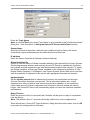
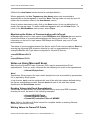
Invoke the Configure/Topic Definition… The "Topic Definition" dialog box will appear:
To define a new topic, click on New. To modify an existing topic, select the topic name
and click on Modify. The "OmronCIP Topic Definition" dialog box will appear:
Omron CIP Communication Server Ver 1.x User Manual Rev 1.1
6001xm11
Omron CIP Communication Server
15
Enter the Topic Name.
Note: If using InTouch, the same Topic Name is to be entered in the "Add Access Name"
dialog box – see description in Using the OmronCIP Server with InTouch section.
Socket Name
Select the Socket to associate it with the topic. Additional topics (Omron NJ-series
Controllers) may be associated with the same Socket at a later time.
IP address
Enter the Omron Controller IP address (Internet Address).
Global Variables file
Select or enter the name of Global Variables definition file exported from Omron Sysmac
Studio programming software and used by Omron CIP Server to validate this Controller
item names and their properties (see Item Names section later in this manual). To export
the Global Variables, at first copy Global Variables to the clipboard by selecting “Tools /
Export Global Variables / CX-Designer” from Omron Sysmac Studio Main menu and then
save the contents of clipboard to the text file with appropriate filename and location.
Update Interval
Set the Update Interval field to indicate the frequency the items/points on this topic
(Omron Controller) should be read (polled). This is requested update rate - at this
frequency the values of all this topic active items must be updated. In real conditions
(when large amount of data is requested from Controller) the real update rate can be
longer - the OmronCIP Server will automatically adjust it to have the maximum possible
performance.
Reply Timeout
Enter the amount of time (in seconds) the Controller will be given to reply to commands
from the Server.
Note: The default value of 3 seconds should be sufficient for most configurations.
When all entries in “OmronCIP Topic Definition” dialog box have been made, click on OK
to process the configuration for this topic.
Omron CIP Communication Server Ver 1.x User Manual Rev 1.1
6001xm11
Omron CIP Communication Server
16
Select Done in "Topic definition" dialog box when configuration for all Topics has been
performed.
Item Names
The Omron CIP Ethernet/IP Communication Server supports item names corresponding
with names of Global Variables used in Omron SYSMAC NJ-series Controller program
and published to the network as inputs, outputs, or publish only variables:
OmronCIP Server uses Global Variables definition file exported from Omron Sysmac
Studio programming software to validate the corresponding Topic (Controller) item names
and their properties.
To export the Global Variables, at first copy Global Variables to the clipboard by selecting
“Tools / Export Global Variables / CX-Designer” from Omron Sysmac Studio Main menu
and then save the contents of clipboard to the text file with appropriate filename and
location.
The item names supported by OmronCIP Server is exactly same as names of Global
Variables used in Omron SYSMAC NJ-series Controller program, except for elements of
arrays the following format is used:
arrayname[x]
where arrayname is the name of Global Variable (array) and x is the index of array
element (x starts from 0); for example, TstArray2[5] is array’s TstArray2 element with
index 5.
Omron CIP Communication Server Ver 1.x User Manual Rev 1.1
6001xm11
Omron CIP Communication Server
17
There is a 1994 bytes maximum length limitation for CIP class 3 connection
(Large_Forward_Open) messages, so the maximum number of items which can be read
by one message depends on read message type. The OmronCIP Server currently
supports two types of read messages:
1) Multiple Services Packet (Service Code 0A) messages, used for reading of single
Global Variables, except array elements. The maximum number of items which can be
read by one Multiple Services Packet message is limited to 32 items (it is limited by length
of request command sent to Controller).
2) Read Service for Variables (Service Code 4C) messages, used for reading of arrays
– in case item name indicates this item is array element, the whole array (starting from
beginning) is read from Controller. Therefore it is important to use the array elements with
small indexes, as the maximum number of items which can be read by one Read Service
for Variables is limited by Controller response message. For example, the maximum
number of DWORD (double word) type array elements which can be read from Controller
is 495 double words.
Note: If possible, it is highly recommended to use arrays – that can greatly increase the
OmronCIP Server performance in case it is necessary to read large amount of data.
For more detailed information about format of Global Variables definition files, please
refer to OneVariable.txt and Variables.txt example Global Variables definition files
installed during the the OmronCIP Server installation.
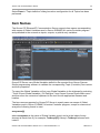
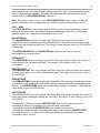
Monitoring and Controlling Communication with a PLC
For each topic, there are following additional items offered by OmronCIP Server to
monitor and control the communication with PLC.
STATUS
For each topic, there is a built-in discrete item that indicates the state of communication
with PLC. The discrete item (STATUS) is set to 0 when communication fails and set to 1
when communication is successful. The STATUS value is set to 0 after 3 consecutive
unsuccessful retries to communicate with this PLC.
From InTouch the state of communication may be read by defining an I/O Discrete
tagname and associating it with the topic configured for the PLC and using STATUS as
the item name.
From Excel, the status of the communication may be read by entering the following
formula in a cell:
=OmronCIP|topic!STATUS
where topic is the name of topic (e.g. plc01) configured for PLC.
UPDATEINTERVAL
The UPDATEINTERVAL item is an Integer type Read/Write item used to access the
currently set Update Interval (see Topic Definition Command section). It indicates the
current requested update interval (in milliseconds). The value of this item can be read
through DDE, Suite Link or OPC. Client can poke new values to this item. The range of
Omron CIP Communication Server Ver 1.x User Manual Rev 1.1
6001xm11
Omron CIP Communication Server
18
valid values is from 10 to 2147483647 milliseconds. The value of zero indicates that no
items on this topic are updated. The write commands are still executed (new values
written to PLC) if UPDATEINTERVAL value is 0.
Note: By poking a value of zero to the UPDATEINTERVAL item, a client can stop all
update activities on the corresponding topic without having to deactivate the items.
POLL_NOW
The POLL_NOW item is an Integer type Write Only item used for immediate one time
polling of all active items; this one time polling is performed when POLL_NOW value
switches from 0 to 1; no effect when switches from 1 to 0.
MAXINTERVAL
The MAXINTERVAL item is an Integer type Read Only item used to access the
measured maximum update interval (in milliseconds) of all items for the corresponding
topic for the last completed poll cycle. The range of valid values is from 0 to 2147483647
milliseconds.
The UPDATEINTERVAL and MAXINTERVAL items can be used to tune the
performance of communication.
ITEMCOUNT
The ITEMCOUNT item is an Integer type Read Only item used to access the number of
active items in the corresponding topic. The range of valid values is from 0 to
2147483647.
ERRORCOUNT
The ERRORCOUNT item is an Integer type Read Only item used to access the number
of active items with errors in the corresponding topic. The range of valid values is from 0
to 2147483647.
ERRORITEMS
The ERRORITEMS item is an Integer type Read/Write Only (unique for each topic) used
to access the total number of items with invalid item names (these items are rejected by
Server). The ERRORITEMS value can be reseted by writing 0 to this item. The range of
valid values is from 0 to 2147483647.
WRITECOUNT
The WRITECOUNT item is an Integer type Read Only item used to access the number of
write commands (messages) waiting for execution. The range of valid values is from 0 to
2147483647.
For example, in following way the WRITECOUNT item can be used to avoid the
increasing of memory occupied by not executed write commands:
- activate the hot link with WRITECOUNT item and start to monitor it;
- activate new write command (by poking new value) only if value of WRITECOUNT
becomes equal to 0, e.g. all previous write commands are executed and memory
occupied by them is freed.
Omron CIP Communication Server Ver 1.x User Manual Rev 1.1
6001xm11
Omron CIP Communication Server
19
SUSPEND
Special Read/Write Discrete Item SUSPEND may be used to control the communication
with a separate topic. If application changes SUSPEND value from 0 to 1 then
communication with topic is suspended. If SUSPEND value is changed back to 0 then
communication with this topic is resumed.
Note: If topic is suspended by setting SUSPEND value to 1, then Server rejects all new
write values to this topic, i.e. no new write messages are created after SUSPEND value
has changed from 0 to 1.
Omron CIP Communication Server Ver 1.x User Manual Rev 1.1
6001xm11
Omron CIP Communication Server
20
Using the OmronCIP Server with Suite Link and
DDE Clients
The “Suite Link & DDE” version of OmronCIP Server is accessible from Suite Link
clients (e.g. InTouch) and DDE clients (e.g. Excel). The “OPC & DDE” version of
OmronCIP Server is accessible from DDE clients.
Using the OmronCIP Server with InTouch
To access to Omron NJ-series Controller Global Variables from InTouch, the Access
Names and Tagnames should be defined in WindowMaker.
Defining the Access Names
InTouch uses Access Names to reference real-time I/O data. Each Access Name
equates to an I/O address, which can contain a Node, Application, and Topic. In a
distributed application, I/O references can be set up as global addresses to a network I/O
Server or local addresses to a local I/O Server.
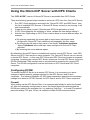
To define the Access Names in WindowMaker node invoke the /Special/Access Names...
command. The "Access Names" dialog box will appear (“Galaxy” and “OPC” are default
already existing Access Names when creating a new InTouch application):
Click on Add…. The "Add Access Name" Dialog Box will appear:
Omron CIP Communication Server Ver 1.x User Manual Rev 1.1
6001xm11
Omron CIP Communication Server
21
Note: If Add is selected, this dialog box will be blank when it initially appears. Data has
been entered here to illustrate the entries that are made.
The following fields are required entries when entering an Access Name Definition:
Access Name
In the Access Name box type the name you want InTouch to use to this Access Name.
(For simplicity, use the same name that you will use for the Topic Name here.)
Node Name
If the data resides in a network I/O Server, in the Node Name box, type the remote node's
name.
Application Name
In the Application Name box, type the actual program name for the I/O Server program
from which the data values will be acquired. In case the values are coming from the
OmronCIP Server the “OmronCIP” is used. Do not enter the .exe extension portion of the
program name.
Topic Name
Enter the name defined for the topic in the OmronCIP Server to identify the topic the
OmronCIP Server will be accessing.
The Topic Name is an application-specific sub-group of data elements. In the case of data
coming from a OmronCIP Server program, the topic name is the exact same name
configured for the topic in the OmronCIP Server.
Note: This will usually be the same as the "Access Name", although, if desired, they may
be different. However, it must be the same name used when the topics were configured in
section Configuring the OmronCIP Server.
Which protocol to use
Select the protocol (DDE or Suite Link) that you are using.
Omron CIP Communication Server Ver 1.x User Manual Rev 1.1
6001xm11
Omron CIP Communication Server
22
When to advise server
Select Advise all items if you want the Server program to poll for all data whether or not
it is in visible windows, alarmed, logged, trended or used in a script. Selecting this option
will impact performance, therefore its use is not recommended.
Select Advise only active items if you want the Server program to poll only points in
visible windows and points that are alarmed, logged, trended or used in any script.
Click OK to accept the new Access Name and close the “Add Access Name” dialog box.
The “Access Names” dialog box will reappear displaying the new Access Name selected
in the list.
Click Close to close the “Access Names” dialog box.
Omron CIP Communication Server Ver 1.x User Manual Rev 1.1
6001xm11
Omron CIP Communication Server
23
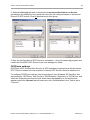
Defining the Tagnames
To define the Tagnames associated with the new "Access Name", invoke the
/Special/Tagname Dictionary... command (in WindowMaker). The "Tagname Dictionary "
dialog box will appear:
Click on New and enter the Tagname. (The tagname defined here is the name InTouch
will use. The OmronCIP Server does not see this name.)
Select the tag type by clicking on the Type:… button. The "Tag Types" dialog box will
appear:
To access OmronCIP items, the type must be I/O Discrete, I/O Integer, I/O real or I/O
Message. Select the Tag type.
The "Details" dialog box for the tagname will appear:
Omron CIP Communication Server Ver 1.x User Manual Rev 1.1
6001xm11
Omron CIP Communication Server
24
Select the Access name for OmronCIP Server by clicking on the Access Name:…
button. The "Access Names" dialog box will appear:
Select the appropriate Access Name and click on Close. (If the Access Name has not
been defined as previously described, click on Add and define the Access Name now.)
The "Details" dialog box will appear displaying the selected Access Name:
For integers and reals fill in the Min EU, Max EU, Min Raw and Max Raw fields. These
fields control the range of values that will be accepted from the Server and how the
values are scaled. If no scaling is desired, Min EU should be equal to Min Raw and Max
EU equal to Max Raw.
Enter the OmronCIP item name to be associated with this tagname in the Item: field in
the "Details" box:
Omron CIP Communication Server Ver 1.x User Manual Rev 1.1
6001xm11
Omron CIP Communication Server
25
(Refer to the Item Names section below for complete details.)
Where applicable, the Use Tagname as Item Name option may be selected to
automatically enter the tagname in this field. Note: The tag name can only be used if it
follows the conventions listed in the Item Names section.
Once all entries have been made, click on the Save button (in the top dialog box) to
accept the new tag name. To define additional tagnames click on the New button. To
return to the WindowMaker main screen, select Close.
Monitoring the Status of Communication with InTouch
InTouch supports built-in topic names called DDEStatus and IOStatus that are used to
monitor the status of communications between the Server and InTouch. For more
information on the built-in topic names DDEStatus and IOStatus, see your InTouch
documentation.
The status of communication between the Server and InTouch can be read into Excel by
entering the following DDE reference formula in a cell on a spreadsheet (in following
examples PLC2 is the Topic Name configured for OmronCIP Server):
=view|DDEStatus!PLC2
or
=view|IOStatus! PLC2
Notes on Using Microsoft Excel
Data from the OmronCIP topic (Unitronics PLC) may be accessed from Excel
spreadsheets. To do so, enter a formula like the following into a cell on the spreadsheet.
= OmronCIP|topic!item
Note!
Sometimes, Excel requires the topic and/or item/points to be surrounded by apostrophes
if it is required by Excel syntax.
In the formula, topic must be replaced with one of the valid topic names defined during
the Server configuration process. Replace item with one of the valid item names
described in the Item Names section.
Reading Values into Excel Spreadsheets
Values may be read directly into Excel spreadsheets by entering a DDE formatted
formula into a cell, as shown in the following examples:
= OmronCIP|PLC2!TstInt
= OmronCIP|NJ501!Real12
= OmronCIP|'controller4'!'Struct1.MEMB2'
Note: Refer to the Microsoft Excel manual for complete details on entering Remote
Reference formulas for cells.
Writing Values to OmronCIP Points
Omron CIP Communication Server Ver 1.x User Manual Rev 1.1
6001xm11
Omron CIP Communication Server
26
Values may be written to the Server from Microsoft Excel by creating an Excel macro that
uses the POKE command. The proper command is entered in Excel as follows:
channel=INITIATE("OmronCIP","topicname")
=POKE(channel,"itemname", Data_Reference)
=TERMINATE (channel)
=RETURN()
The following describes each of the above POKE macro statements:
channel=INITIATE("OmronCIP","topicname")
Opens a channel to a specific topic name (defined in the Server) in an application with
name OmronCIP (the executable name less the .EXE) and assigns the number of that
opened channel to channel.
Note: By using the channel=INITIATE statement the word channel must be used in
the =POKE statement instead of the actual cell reference. The "applicationname"
and "topicname" portions of the formula must be enclosed in quotation marks.
=POKE(channel,"itemname", Data_Reference)
POKEs the value contained in the Data_Reference to the specified item name (actual
location in the Unitronics PLC) via the channel number returned by the previously
executed INITIATE function. Data_Reference is the row/column ID of the cell containing
the data value. For "itemname", use some of the valid item names described in the Item
Names section.
=TERMINATE(channel)
Closes the channel at the end of the macro. Some applications have a limited number of
channels. Therefore they should be closed when finished. Channel is the channel
number returned by the previously executed INITIATE function.
=RETURN()
Marks the end of the macro.
The following is an example of Excel macro used to poke value from cell B2 to topic
PLC2 item TstInt:
PokeMacro -Ctrl a
=INITIATE("OmronCIP","PLC2")
=POKE(A2,"TstInt",B2)
=ON.TIME(NOW()+0.01,"TerminateDDEChannel")
=RETURN()
TerminateDDEChannel
=TERMINATE(A2)
=RETURN()
Note: Refer to the Microsoft Excel manual for complete details on entering Remote
Reference formulas for cells.
Omron CIP Communication Server Ver 1.x User Manual Rev 1.1
6001xm11
Omron CIP Communication Server
27
Using the OmronCIP Server with OPC Clients
The “OPC & DDE” version of OmronCIP Server is accessible from OPC Clients.
There are following general steps needed to access an OPC item from OmronCIP Server:
1.
2.
3.
4.
Run OPC Client application and select the “OmronCIP OPC and DDE Server” from
the list of available OPC Servers. If OmronCIP Server currently is not running, it will
start automatically.
Create a new group (or topic if Wonderware OPCLink application is used).
If OPC Client supports the validating of items, validate the item before adding it.
Add the item. Depending on OPC Client it can be done in several different ways, for
example:
a) By entering separately the access path to topic name (valid topic name
configured in OmronCIP Topic definition) and separately the item name.
b) By entering the full path to item name in the format TopicName.ItemName
where TopicName is the valid topic name configured in OmronCIP Topic
definition.
c) By browsing the server address space.
By default the OmronCIP Server is installed and used as a local OPC Server - both OPC
Server and OPC Client reside on same computer. The OmronCIP Server can run also as
a remote OPC Server – in this case OPC Server and OPC Client are located on separate
computers. Accessing the remote OPC Server is same as for local OPC Server, but some
DCOM (Distributed COM) configuration is required before accessing the remote OPC
Server. The DCOM configuration must be done both on OPC Server and OPC Client
computers.
Configuring DCOM
To access OmronCIP Server as a remote OPC Server, it is necessary to do some
changes in default security settings selected for the OPC Server’s and Client’s
computers. The following Windows XP SP2 based explanation describes the necessary
settings to be done for XP SP2 firewall, for OPC Server and for OPC Client computers.
Firewall
When setting up the OPC Server/Client, it is recommended initially to switch the firewall
off. After the necessary configuration is done, the firewall should be restarted and the
DCOM port added to the exception list – by selecting ”Add Port...” in firewall ”Exceptions”
pane and adding TCP port 135 as it is needed to initiate DCOM communications:
Omron CIP Communication Server Ver 1.x User Manual Rev 1.1
6001xm11
Omron CIP Communication Server
28
As well by selecting the ”Add Program...”, all necessary OPC Server and OPC Client
programs should be added to the exception list.
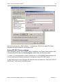
OmronCIP OPC Server settings
After OmronCIP Server “OPC & DDE” version installation, the System Administrator must
configure DCOM by using the dcomcnfg.exe system utility, the following steps:
1. At first, it is recommended to create a local group (i.e. OPCUSERS) that contains a list
of all the users who will have permission to access the OmronCIP OPC server.
2. Start dcomcnfg.exe from Windows XP Start-Run line and select the “OmronCIP OPC &
DDE Server” from the list of DCOM entries:
Omron CIP Communication Server Ver 1.x User Manual Rev 1.1
6001xm11
Omron CIP Communication Server
29
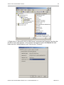
3. Right click on “OmronCIP OPC & DDE Server” and select the Poperties item from the
pull down menu that appears. In the window that appears select the General tab and
make sure the ”Authentication Level” field is set to ”Connect”:
Omron CIP Communication Server Ver 1.x User Manual Rev 1.1
6001xm11
Omron CIP Communication Server
30
4. Select the Security tab and customize the Launch and Activation and Access
permissions by adding the user group with user who will have permission to access the
OmronCIP OPC server. Give all permissions to that group:
5. Now the configuration of OPC Server is completed – close the dcomcnfg program and
restart the OmronCIP OPC Server to put new settings into effect.
OPCEnum settings
OPCEnum (OPC Enumeration Service) is OPC standard component that allows remote
OPC Client to browse the local machine to identify OPC Servers that are installed on it.
To configure OPCEnum settings, start dcomcnfg.exe from Windows XP Start-Run line
and select the “OPCEnum” from the list of DCOM entries. Right click on “OPCEnum” and
select the Poperties item from the pull down menu that appears. In the window that
appears select the General tab and make sure the ”Authentication Level” field is set to
”Connect”:
Omron CIP Communication Server Ver 1.x User Manual Rev 1.1
6001xm11
Omron CIP Communication Server
31
Select the Security tab and customize the Launch and Activation and Access
permissions by adding the user group OPCUSERS same way like for “OmronCIP OPC &
DDE Server”. Give all permissions to that group.
OPC Client side settings
To configure necessary settings on OPC Client computer:
1. Start dcomcnfg.exe from Windows XP Start-Run line, navigate to and right click on “My
Computer” and select Poperties item from the pull down menu that appears. In the
window that appears select the Default Properties tab and make sure the settings there
are filled like as shown below:
Omron CIP Communication Server Ver 1.x User Manual Rev 1.1
6001xm11
Omron CIP Communication Server
32
2. Select the Com Security tab and edit the Default settings for Access Permissions by
adding (if not yet added) ANONYMOUS LOGON and giving it all access permissions. Do
the same also for ”Edit Limits”:
3. Edit the Default settings for Launch and Activation Permissions by adding (if not yet
added) ANONYMOUS LOGON and giving it all all access permissions. Do the same also
for ”Edit Limits”.
Omron CIP Communication Server Ver 1.x User Manual Rev 1.1
6001xm11
Omron CIP Communication Server
33
Note!
In case the ”Edit Limits” selections are not available (grayed) that would mean the DCOM
Security Options for some reason have Security Setting other than ”Not defined”. To
correct that: select Control Panel/ Administrative Tools/Local Security Policy and select
Local Policies/Security Options in ”Local ”Security Settings” dialog box; select, right click
and invoke Properties for ”DCOM: Machine Access Restrictions... ” and ”DCOM: Machine
Launch Restrictions... ” and change their ”Security Setting” to ”Not defined”.
4. Now the configuration of OPC Client side is is completed – close the dcomcnfg
program and restart the OPC Client.
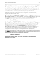
Running OmronCIP “OPC & DDE” version as Windows Service
To install OmronCIP Server “OPC & DDE” version to run as Windows Service, the
OmronCIP Server must be started with command line parameter "/Service":
OmronCIP /Service
After this the “OmronCIP OPC & DDE Server” Service will be installed with Startup type
“Manual”. The Service Startup configuration can be changed by MS Windows XP Control
Panel/Administrative Tools/Services configuration. The Allow service to interact with
desktop checkbox in “Log On” tab must be checked (the “Log On” tab can be invoked
from Poperties item from the pull down menu that appears when right clicking on
OmronCIP OPC & DDE Server Service). If Allow service to interact with desktop is
not selected then OmronCIP Server full functionality is not ensured (e.g. the Server
configuration can not be changed, no message boxes will be displayed, etc.).
To uninstall “OmronCIP OPC & DDE Server” Service, at first the Service must be stopped
by Control Panel/ Administrative Tools/Services/Stop and then OmronCIP Server must be
started manually with command line parameter "/DelService":
OmronCIP /DelService
After this the OmronCIP Server “OPC & DDE” version will be still registered and
accessible to OPC Clients.
Omron CIP Communication Server Ver 1.x User Manual Rev 1.1
6001xm11
Omron CIP Communication Server
34
Troubleshooting
WIN.INI entries
The first time you run the OmronCIP Server configuration, most of the items in the
following list will automatically appear in the WIN.INI file, located in the MS Windows
system directory (e.g. C:\WINNT). It is an ASCII file and can be altered manually if you
wish with any text editor, e.g., MS Windows Notepad (do not use a program that formats
text, such as MS Word or Write unless the file is saved as a DOS text). The following is a
typical entry for the OmronCIP Server:
[OmronCIP]
ProtocolTimer=10
ConfigurationFile=C:\OmronCIP\
WinIconic=0
WinFullScreen=0
WinTop=110
WinLeft=0
WinWidth=200
WinHeight=170
DumpScreen=1
The following additional entries can be used:
SlowPollRetries and SlowPollInterval
The SlowPollRetries entry is used to enter the number of consecutive error retries for
one topic. If after SlowPollRetries there is still no successful response from unit
(Unitronics PLC), then this topic is changed to slow poll mode. The WIN.INI file
SlowPollInterval entry is used to enter the slow poll mode update interval (in seconds).
Entering into slow poll mode is reported to WWLogger and (or) to OmronCIP Internal
Logger by following string:
"Node:<NODENAME> Topic:<TOPICNAME>. Set slow poll mode - poll after each
%ld secs. Stop error logging to topic."
Leaving the slow poll mode is reported to WWLogger and (or) to OmronCIP Internal
Logger by following string:
"Node:<NODENAME> Topic:<TOPICNAME>. Return to normal communication to
topic. Error logging reestablished"
The default values (they are used if WIN.INI file does not contain these entries) are
SlowPollRetries equal to 5 and SlowPollInterval equal to 60 seconds.
MultiWrite
If MultiWrite=1 entry is added to WIN.INI file [OmronCIP] section then write commands
are processed in the following way: if server receives some new value to be written to unit
and other writing command to same UNIT address is still pending (waiting for execution)
Omron CIP Communication Server Ver 1.x User Manual Rev 1.1
6001xm11
Omron CIP Communication Server
35
then no new write command is created - the value in existing write command is replaced
by new one. As default (no MultiWrite entry or MultiWrite=0) all write values are
delivered to UNIT, i.e. always new write command is created.
If MultiWrite=2 then Server tries to include the new write value into the some of
previously created messages ignoring the sequence of data changing in the client
application. Server can include into one message only the consecutive item values.
Example: value of MI100 in message with values of items MI99 or MI101.
Important! If MultiWrite=2 then maximum writing speed is achieved, but this option is
not recommended if data changing sequence is important for PLC program!
WriteCapacity
The WriteCapacity entry can be used to specify how many values can be sent (written)
by one write message. The WriteCapacity value becomes effective only starting with
second pending write message, i.e. the first pending write message always will contain
one value. The WriteCapacity entry is relevant only if parameter MultiWrite=2. The
WriteCapacity default value is 1.
MessageRetries
The MessageRetries= entry can be used to specify how many times the OmronCIP
server will try to send any command to PLC. After MessageRetries expires the next
command will be tried. As default (no MessageRetries entry or MessageRetries=2) the
MessageRetries equal to 2 will be used. Note - the topic STATUS item value will change
to 0 when MessageRetries expires.
WriteRetries
The WriteRetries= entry can be used only for write commands to specify how many
times write command will be tried to send. The WriteRetries entry is used together with
MessageRetries in the following way: if after WriteRetries * MessageRetries there is
still no response from PLC then this write command is removed from list of pending write
commands and will be no more executed. As default (no WriteRetries entry or
WriteRetries=3 the WriteRetries equal to 3 will be used. So, if default settings
(MessageRetries=2 and WriteRetries=3) are used, the write command will be deleted
after 6 unsuccessful retries.
Examples:
- by settings MessageRetries=2 and WriteRetries=1 the OmronCIP server will delete
write command after 2 unsuccessful retries;
- by settings MessageRetries=1 and WriteRetries=1 the OmronCIP server will delete
write command immediately after first unsuccessful retry.
FirstPollDelay
The FirstPollDelay= entry can be used to specify how long is pause (delay) between
connection establishing and first poll request issue. As default (no FirstPollDelay entry or
FirstPollDelay=0) the FirstPollDelay equal to 0 will be used.
FirstWDDelay
The FirstWDDelay = entry can be used to specify how long is pause (delay) between
connection establishing and first watchdog write message issue. As default (no
FirstWDDelay entry or FirstWDDelay=0) the FirstWDDelay equal to 0 will be used.
Omron CIP Communication Server Ver 1.x User Manual Rev 1.1
6001xm11
Omron CIP Communication Server
36
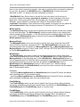
Troubleshooting menu
The following debugging choices are appended to the Server’s System Menu (the menu
that appears when you click on the Server icon in the upper left hand corner of the
Server's window):
Suspend Protocol/Resume Protocol - these choices permit you to turn protocol
processing on and off, what means that you can suspend access to
Controller(s).
Show Send
- if checked then all outgoing user data logged in hexadecimal format.
Show Receive
- if checked then all incoming user data logged in hexadecimal format.
Show Errors
- if checked then all information about errors is logged.
Show Rejected Writes
- this option can be useful in situation when communication
with some topic (topics) is suspended by using the SUSPEND item
(see Item Names section) and the Server rejects all writes (pokes) to
this topic (topics). If checked then information about each rejected
write (poke) value is logged. If not checked (default) then Server
rejects all writes (pokes) to suspended topic(s) without logging any
information.
Verbose
- if checked then additional debugging information is displayed.
Dump
- all information about ports, topics, messages and data items logged.
This can be use to find out how many messages are actually sent to
the PLC(s).
Dump Screen
- if checked then information about active messages are displayed on
the OmronCIP main window. This also can be used to find out how
many messages are actually sent to the PLC(s).
Show Logger
- this selection is available only for OmronCIP “OPC & DDE” version. If
checked then OmronCIP Internal Logger is activated and all debug
information is going to OmronCIP Internal Logger. The OmronCIP
Internal Logger file is named in the format:
OmronCIP_YYYYMMDD.LOGn
where YYYY is a year, MM is a month, DD is a day and n is a order
number of consecutive OmronCIP Internal Logger file, starting from 1
(the OmronCIP Internal Logger file maximum size is 16 MB; if there is
more information logged then next consecutive file is created, e.g.
there can be consecutive files OmronCIP_19990413.LOG1,
OmronCIP_19990413.LOG2, etc.).
All OmronCIP debug information (except Dump Screen) is displayed through the
ArchestrA SMC Log Viewer (Wonderware Logger) or OmronCIP Internal Logger (in case
Show Logger is checked), which must be active for these commands to work.
Note: If you check Show Send and/or Show Receive debug output grows very fast and
it is possible that computer can become very slow.
Omron CIP Communication Server Ver 1.x User Manual Rev 1.1
6001xm11
Omron CIP Communication Server
37
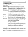
Internal Logger
The OmronCIP “OPC & DDE” version supports the Internal Logger. To enable the
OmronCIP Internal Logger, check the Show Logger option at the OmronCIP Server
System Menu (see Troubleshooting menu section above) - this command can be used to
start/stop the Internal Logger. The Internal Logger window looks like following:
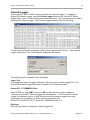
To save Internal Logger information to file, select Options/Disk Options… from Internal
Logger main menu – the “Disk Options” dialog box will appear:
The following can be entered in this dialog box:
Log to File
If checked then Internal Logger information will be saved to Internal Logger File. The
OmronCIP Internal Logger file name is created in the following format:
OmronCIP _YYYYMMDD.LOGn
where YYYY is a year, MM is a month, DD is a day and n is a order number of
consecutive OmronCIP Internal Logger file, starting from 1. The OmronCIP Internal
Logger file maximum size is 16 MB; if there is more information logged then next
consecutive file is created, e.g. there can be consecutive files
OmronCIP_20030228.LOG1, OmronCIP_20030228.LOG2, etc.
Directory
Enter the path where to keep the Internal Logger File.
Omron CIP Communication Server Ver 1.x User Manual Rev 1.1
6001xm11
Omron CIP Communication Server
38
Keep Log File for
Here the number of days how long to keep the Internal Logger File can be entered. After
this number of days expires, the corresponding Internal Logger File will be automatically
deleted. The default value 0 keeps Internal Logger Files forever - in this case they can be
deleted manually.
Options/Font
To configure the font used by Internal Logger, select Options/Font… from Internal Logger
main menu - the “Font” dialog box will appear:
Omron CIP Communication Server Ver 1.x User Manual Rev 1.1
6001xm11
Omron CIP Communication Server
39
KLINKMANN AUTOMATION
Omron CIP Ethernet/IP Communication Server
Revision History
Date
Number
Notes
Mar 2014
Mar 2014
Rev 1.0
Rev 1.1
First Release
Item Names section modified, arrays added.
Omron CIP Communication Server Ver 1.x User Manual Rev 1.1
6001xm11