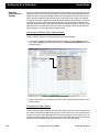
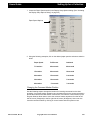
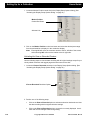
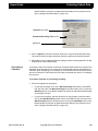
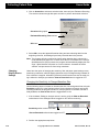
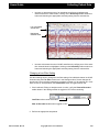
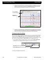
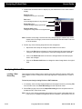
Download Ceegraph Vision Users Manual
Transcript
Ceegraph Vision Computerized Electroencephalography Program Version 7.10 User’s Manual Copyright © 2006 Bio-logic Systems Corp Part Number 590-CGVUM1, Rev B COPYRIGHT © BIO-LOGIC SYSTEMS CORP 2006 is the year that this unpublished work was originally created. BIO-LOGIC SYSTEMS CORP (“Bid-logic”) owns the right to this work and intends to maintain the contents as a trade secret. Bid-logic may also seek to maintain this work as an unpublished copyright. In the event of an inadvertent or deliberate publication, Bio-logic intends to enforce its right to this under the copyright laws as a published work. Those having access to this work may not copy, use or disclose the information in this work unless expressly authorized by Bio-logic to do so. Bio-logic Systems Corp One Bio-logic Plaza Mundelein, Illinois 60060-3700 1 800 323-8326 Local Phone 1 847949-5200 Fax 1 847 949-8615 http://www.bio-logic.com Bio-logic is a registered trademark of Bio-logic Systems Corp, a Natus Company Ceegraph Vision is a trademark of Bio-logic Systems Corp Netlink is a trademark of Bio-logic Systems Corp. P&TI is a trademark of Bio-logic Systems Corp. PTI Utilities is a trademark of Bio-logic Systems Corp. dataShare is a trademark of Bio-logic Systems Corp IBM is a registered trademark of International Business Machines Corporation. Microsoft, Windows and MS-DOS are registered trademarks of Microsoft Corporation. Microsoft Word is a registered trademark of Microsoft Corporation. Stellate is a registered trademark of Stellate Systems. Persyst is a registered trademark of Persyst Development Corp. MagicMarker is a registered trademark of Persyst Development Corp. ii Ceegraph Vision Users Manual 590-CGVUM1, Rev B Table of Contents Chapter 1: Introduction Product Description . . . . . . . . . . . . . . . . . . . . . . . . . . . . . . . . . . . . . . . . . . . . . . . . . 1 Data Collection Features . . . . . . . . . . . . . . . . . . . . . . . . . . . . . . . . . . . . . . . . . . . . 1 Data Analysis Features . . . . . . . . . . . . . . . . . . . . . . . . . . . . . . . . . . . . . . . . . . . . . 1 System Layout . . . . . . . . . . . . . . . . . . . . . . . . . . . . . . . . . . . . . . . . . . . . . . . . . . . . 1 Computer Requirements . . . . . . . . . . . . . . . . . . . . . . . . . . . . . . . . . . . . . . . . . . . . . 1 Computer . . . . . . . . . . . . . . . . . . . . . . . . . . . . . . . . . . . . . . . . . . . . . . . . . . . . . . . . 1 Mouse . . . . . . . . . . . . . . . . . . . . . . . . . . . . . . . . . . . . . . . . . . . . . . . . . . . . . . . . . . . 1 Safety Standards . . . . . . . . . . . . . . . . . . . . . . . . . . . . . . . . . . . . . . . . . . . . . . . . . . 1 Data Acquisition Module (Headbox) . . . . . . . . . . . . . . . . . . . . . . . . . . . . . . . . . . . 2 Computer Options . . . . . . . . . . . . . . . . . . . . . . . . . . . . . . . . . . . . . . . . . . . . . . . . . . 2 Printer . . . . . . . . . . . . . . . . . . . . . . . . . . . . . . . . . . . . . . . . . . . . . . . . . . . . . . . . . . . 2 Data Compression . . . . . . . . . . . . . . . . . . . . . . . . . . . . . . . . . . . . . . . . . . . . . . . . . 2 Digital Video . . . . . . . . . . . . . . . . . . . . . . . . . . . . . . . . . . . . . . . . . . . . . . . . . . . . . 2 Stellate . . . . . . . . . . . . . . . . . . . . . . . . . . . . . . . . . . . . . . . . . . . . . . . . . . . . . . . . . . 2 Persyst Spike and Seizure . . . . . . . . . . . . . . . . . . . . . . . . . . . . . . . . . . . . . . . . . . . 2 Screen Areas . . . . . . . . . . . . . . . . . . . . . . . . . . . . . . . . . . . . . . . . . . . . . . . . . . . . . . . 3 Main Menu and Comment Marker Area . . . . . . . . . . . . . . . . . . . . . . . . . . . . . . . . 3 Waveform Display Area . . . . . . . . . . . . . . . . . . . . . . . . . . . . . . . . . . . . . . . . . . . . 3 Toolbar Button Area . . . . . . . . . . . . . . . . . . . . . . . . . . . . . . . . . . . . . . . . . . . . . . . 4 Message and Scroll Bar Area . . . . . . . . . . . . . . . . . . . . . . . . . . . . . . . . . . . . . . . . . 4 Collection Screen Buttons . . . . . . . . . . . . . . . . . . . . . . . . . . . . . . . . . . . . . . . . . . . . 4 Lookback Toolbar Button . . . . . . . . . . . . . . . . . . . . . . . . . . . . . . . . . . . . . . . . . . . 4 Photic Toolbar Buttons . . . . . . . . . . . . . . . . . . . . . . . . . . . . . . . . . . . . . . . . . . . . . 4 Hyperventilation (HV) Toolbar Button . . . . . . . . . . . . . . . . . . . . . . . . . . . . . . . . . 4 Reset Amplifiers Toolbar Button . . . . . . . . . . . . . . . . . . . . . . . . . . . . . . . . . . . . . . 4 Calibration Signals Toolbar Button . . . . . . . . . . . . . . . . . . . . . . . . . . . . . . . . . . . . 5 Sensitivity Toolbar Combo Box . . . . . . . . . . . . . . . . . . . . . . . . . . . . . . . . . . . . . . 5 Low Filter Control Toolbar Combo Box . . . . . . . . . . . . . . . . . . . . . . . . . . . . . . . . 5 High Filter Control Toolbar Combo Box . . . . . . . . . . . . . . . . . . . . . . . . . . . . . . . . 5 Notch Filter Button . . . . . . . . . . . . . . . . . . . . . . . . . . . . . . . . . . . . . . . . . . . . . . . . 5 Paper Speed Control Toolbar Combo Box . . . . . . . . . . . . . . . . . . . . . . . . . . . . . . 5 Select Display Montage Toolbar Button . . . . . . . . . . . . . . . . . . . . . . . . . . . . . . . . 5 Time Toolbar Button and Icon . . . . . . . . . . . . . . . . . . . . . . . . . . . . . . . . . . . . . . . . 5 Message and Information Area . . . . . . . . . . . . . . . . . . . . . . . . . . . . . . . . . . . . . . . 5 Analysis Screen Buttons . . . . . . . . . . . . . . . . . . . . . . . . . . . . . . . . . . . . . . . . . . . . . . 6 Paging Arrow Buttons . . . . . . . . . . . . . . . . . . . . . . . . . . . . . . . . . . . . . . . . . . . . . . 6 Table of Contents (Continued) Paging Speed (p/s) Control Box . . . . . . . . . . . . . . . . . . . . . . . . . . . . . . . . . . . . . . 6 Begin Scroll and Stop Buttons . . . . . . . . . . . . . . . . . . . . . . . . . . . . . . . . . . . . . . . . 6 Adjust Scroll Speed Slide Bar Icon . . . . . . . . . . . . . . . . . . . . . . . . . . . . . . . . . . . . 6 Move Back One Frame & Move Forward One Frame Buttons . . . . . . . . . . . . . . . 6 Previous File and Next File Buttons . . . . . . . . . . . . . . . . . . . . . . . . . . . . . . . . . . . 6 File Bar Control . . . . . . . . . . . . . . . . . . . . . . . . . . . . . . . . . . . . . . . . . . . . . . . . . . . 6 View as Recorded Toolbar Button . . . . . . . . . . . . . . . . . . . . . . . . . . . . . . . . . . . . . 6 Sensitivity Toolbar Combo Box . . . . . . . . . . . . . . . . . . . . . . . . . . . . . . . . . . . . . . 6 Low Filter Control Toolbar Combo Box . . . . . . . . . . . . . . . . . . . . . . . . . . . . . . . . 7 High Filter Control Toolbar Combo Box . . . . . . . . . . . . . . . . . . . . . . . . . . . . . . . . 7 Notch Filter Button . . . . . . . . . . . . . . . . . . . . . . . . . . . . . . . . . . . . . . . . . . . . . . . . 7 Paper Speed Control Toolbar Combo Box . . . . . . . . . . . . . . . . . . . . . . . . . . . . . . 7 Digital Video . . . . . . . . . . . . . . . . . . . . . . . . . . . . . . . . . . . . . . . . . . . . . . . . . . . . . 7 SetTAG Toolbar Button . . . . . . . . . . . . . . . . . . . . . . . . . . . . . . . . . . . . . . . . . . . . . 7 ShowTAG Button . . . . . . . . . . . . . . . . . . . . . . . . . . . . . . . . . . . . . . . . . . . . . . . . . . 7 Time of Day/Elapsed Time Button . . . . . . . . . . . . . . . . . . . . . . . . . . . . . . . . . . . . 7 Select Display Montage Toolbar Button . . . . . . . . . . . . . . . . . . . . . . . . . . . . . . . . 8 Message and Information Area . . . . . . . . . . . . . . . . . . . . . . . . . . . . . . . . . . . . . . . 8 Finding Help . . . . . . . . . . . . . . . . . . . . . . . . . . . . . . . . . . . . . . . . . . . . . . . . . . . . . . . 8 Ceegraph Vision Help . . . . . . . . . . . . . . . . . . . . . . . . . . . . . . . . . . . . . . . . . . . . . . 8 Customer Support . . . . . . . . . . . . . . . . . . . . . . . . . . . . . . . . . . . . . . . . . . . . . . . . . 8 Chapter 2: User’s Guide Launching Ceegraph Vision . . . . . . . . . . . . . . . . . . . . . . . . . . . . . . . . . . . . . . . . . . 9 From the System Desktop . . . . . . . . . . . . . . . . . . . . . . . . . . . . . . . . . . . . . . . . . . . 9 From the Start Menu . . . . . . . . . . . . . . . . . . . . . . . . . . . . . . . . . . . . . . . . . . . . . . . 9 Automatically Updating the Headbox Code . . . . . . . . . . . . . . . . . . . . . . . . . . . . 10 Automatic Calibrations . . . . . . . . . . . . . . . . . . . . . . . . . . . . . . . . . . . . . . . . . . . . 10 Setting Up for a Collection . . . . . . . . . . . . . . . . . . . . . . . . . . . . . . . . . . . . . . . . . . . 11 Setting Up P&TI . . . . . . . . . . . . . . . . . . . . . . . . . . . . . . . . . . . . . . . . . . . . . . . . . 11 Entering Path Name Labels and Data Paths . . . . . . . . . . . . . . . . . . . . . . . . . . 11 Assigning Default P&TI Database Locations . . . . . . . . . . . . . . . . . . . . . . . . . 13 Defining P&TI Topic Lists . . . . . . . . . . . . . . . . . . . . . . . . . . . . . . . . . . . . . . . 14 Customizing P&TI Test Result Templates . . . . . . . . . . . . . . . . . . . . . . . . . . . 15 Adding a Text Template . . . . . . . . . . . . . . . . . . . . . . . . . . . . . . . . . . . . . . . 16 Editing a Text Template . . . . . . . . . . . . . . . . . . . . . . . . . . . . . . . . . . . . . . . 17 Deleting a Text Template . . . . . . . . . . . . . . . . . . . . . . . . . . . . . . . . . . . . . . 18 Changing P&TI Field Name Labels . . . . . . . . . . . . . . . . . . . . . . . . . . . . . . . . 19 Altering Fields in the P&TI Table View Screen . . . . . . . . . . . . . . . . . . . . . . . 20 Altering Fields in the P&TI Form View Screen . . . . . . . . . . . . . . . . . . . . . . . 21 Adding Fields . . . . . . . . . . . . . . . . . . . . . . . . . . . . . . . . . . . . . . . . . . . . . . . 22 Table of Contents (Continued) Removing Fields . . . . . . . . . . . . . . . . . . . . . . . . . . . . . . . . . . . . . . . . . . . . . 22 Repositioning Fields . . . . . . . . . . . . . . . . . . . . . . . . . . . . . . . . . . . . . . . . . . 23 Changing the Field Tabbing Order . . . . . . . . . . . . . . . . . . . . . . . . . . . . . . . 23 Viewing Field Speed Menu Options . . . . . . . . . . . . . . . . . . . . . . . . . . . . . . 24 Saving Field and Field Label Changes . . . . . . . . . . . . . . . . . . . . . . . . . . . . 25 Selecting Display Screen Options . . . . . . . . . . . . . . . . . . . . . . . . . . . . . . . . . . . . 26 Activating the Display Setup Options Dialog . . . . . . . . . . . . . . . . . . . . . . . . . 26 Changing the Paper Speed . . . . . . . . . . . . . . . . . . . . . . . . . . . . . . . . . . . . . . . 26 Changing the Comment Marker Position . . . . . . . . . . . . . . . . . . . . . . . . . . . . 27 Activating the View as Recorded Feature . . . . . . . . . . . . . . . . . . . . . . . . . . . . 28 Activating the Clip to Baseline Feature . . . . . . . . . . . . . . . . . . . . . . . . . . . . . 29 Tiling Lookback Windows Vertically or Horizontally . . . . . . . . . . . . . . . . . . 29 Displaying Specific Comment Categories . . . . . . . . . . . . . . . . . . . . . . . . . . . 30 Displaying Comments in a Multi-File Recording . . . . . . . . . . . . . . . . . . . . . . 32 Changing the Spacing Between Grid Lines . . . . . . . . . . . . . . . . . . . . . . . . . . 32 Changing the Paging Speed . . . . . . . . . . . . . . . . . . . . . . . . . . . . . . . . . . . . . . 33 Saving Display Setup Option Changes . . . . . . . . . . . . . . . . . . . . . . . . . . . . . . 34 Selecting Signal Settings for Square Wave Calibrations . . . . . . . . . . . . . . . . . . . 35 Setting up Photic Sequences . . . . . . . . . . . . . . . . . . . . . . . . . . . . . . . . . . . . . . . . 35 Setting up Hyperventilation Times . . . . . . . . . . . . . . . . . . . . . . . . . . . . . . . . . . . 36 Changing Screen Color Options . . . . . . . . . . . . . . . . . . . . . . . . . . . . . . . . . . . . . 37 Editing Comment Definitions . . . . . . . . . . . . . . . . . . . . . . . . . . . . . . . . . . . . . . . 38 Selecting Trend Window Options . . . . . . . . . . . . . . . . . . . . . . . . . . . . . . . . . . . . 39 Adding a Facility Name . . . . . . . . . . . . . . . . . . . . . . . . . . . . . . . . . . . . . . . . . . . . 41 Changing the System Number Assignment . . . . . . . . . . . . . . . . . . . . . . . . . . . . . 41 Selecting Impedance Limits . . . . . . . . . . . . . . . . . . . . . . . . . . . . . . . . . . . . . . . . . 42 Changing the Esc Key to a Keyboard Shortcut . . . . . . . . . . . . . . . . . . . . . . . . . . 42 Configuring Mail Clients, Program Applications and Browsers . . . . . . . . . . . . . 43 Activating the iEEG Setup Dialog . . . . . . . . . . . . . . . . . . . . . . . . . . . . . . . . . 43 Adding Comments to an HTML File . . . . . . . . . . . . . . . . . . . . . . . . . . . . . . . 44 Selecting an Image Format and Resolution . . . . . . . . . . . . . . . . . . . . . . . . . . 45 Selecting E-Mail Options . . . . . . . . . . . . . . . . . . . . . . . . . . . . . . . . . . . . . . . . 46 Changing the HTML File Storage Directory . . . . . . . . . . . . . . . . . . . . . . . . . 47 Adding or Removing Application Shortcuts . . . . . . . . . . . . . . . . . . . . . . . . . . 47 Selecting Stripping Options . . . . . . . . . . . . . . . . . . . . . . . . . . . . . . . . . . . . . . . . . 48 Enabling Stellate Processors . . . . . . . . . . . . . . . . . . . . . . . . . . . . . . . . . . . . . . . . 51 Activating DC Channel Alerts . . . . . . . . . . . . . . . . . . . . . . . . . . . . . . . . . . . . . . . 52 Setting up for a Periodic Collection . . . . . . . . . . . . . . . . . . . . . . . . . . . . . . . . . . . 53 Activating the Periodic Collection Setup dialog . . . . . . . . . . . . . . . . . . . . . . . 53 Event Recording Tab Menu Screen . . . . . . . . . . . . . . . . . . . . . . . . . . . . . . . . 53 Continuous Recording Tab Menu Screen . . . . . . . . . . . . . . . . . . . . . . . . . . . . 54 Periodic Interval Tab Menu Screen . . . . . . . . . . . . . . . . . . . . . . . . . . . . . . . . . 56 Summary Tab Menu Screen . . . . . . . . . . . . . . . . . . . . . . . . . . . . . . . . . . . . . . 57 Table of Contents (Continued) Setting Up for an Automatic Archive . . . . . . . . . . . . . . . . . . . . . . . . . . . . . . . . . 58 Creating or Editing Display Montages . . . . . . . . . . . . . . . . . . . . . . . . . . . . . . . . 59 Changing to an Alternate Collection Montage . . . . . . . . . . . . . . . . . . . . . . . . 60 Creating and Saving a New Display Montage . . . . . . . . . . . . . . . . . . . . . . . . 61 Changing the Number of Channels in a Display Montage . . . . . . . . . . . . . . . 61 Changing the Channel Input Labels . . . . . . . . . . . . . . . . . . . . . . . . . . . . . . . . 62 Changing the Montage Scheme for a Display Montage . . . . . . . . . . . . . . . . . 63 Changing the Sensitivity Settings . . . . . . . . . . . . . . . . . . . . . . . . . . . . . . . . . . 64 Changing High and Low Filter Settings . . . . . . . . . . . . . . . . . . . . . . . . . . . . . 66 Changing the Notch Filter Settings . . . . . . . . . . . . . . . . . . . . . . . . . . . . . . . . . 68 Inverting the DC Channel Waveforms . . . . . . . . . . . . . . . . . . . . . . . . . . . . . . 70 Changing the Color of Channel Waveforms . . . . . . . . . . . . . . . . . . . . . . . . . . 71 Saving a Montage as the Program Default . . . . . . . . . . . . . . . . . . . . . . . . . . . 73 Deleting an Unwanted Display Montage . . . . . . . . . . . . . . . . . . . . . . . . . . . . 74 Creating or Editing Collection Montages . . . . . . . . . . . . . . . . . . . . . . . . . . . . . . 75 Loading an Alternate Collection Montage . . . . . . . . . . . . . . . . . . . . . . . . . . . 76 Creating a New Collection Montage. . . . . . . . . . . . . . . . . . . . . . . . . . . . . . . . 76 Changing the Low Filter Settings in a Collection Montage. . . . . . . . . . . . . . 77 Changing the Collection Montage Input Ranges . . . . . . . . . . . . . . . . . . . . . . 79 Enabling or Disabling a Montage Channel. . . . . . . . . . . . . . . . . . . . . . . . . . . 80 Renaming Channel Electrodes . . . . . . . . . . . . . . . . . . . . . . . . . . . . . . . . . . . . 81 Saving the Collection Montage as the Program Default. . . . . . . . . . . . . . . . . 81 Deleting a Collection Montage. . . . . . . . . . . . . . . . . . . . . . . . . . . . . . . . . . . . 82 Pre-collection Activities . . . . . . . . . . . . . . . . . . . . . . . . . . . . . . . . . . . . . . . . . . . . . 82 Performing a Manual Calibration . . . . . . . . . . . . . . . . . . . . . . . . . . . . . . . . . . . . 82 Viewing Calibration Signals . . . . . . . . . . . . . . . . . . . . . . . . . . . . . . . . . . . . . . . . 83 Calibrating External Devices on DC Channels Prior to a Collection . . . . . . . . . 84 Entering Patient Information & a Test ID . . . . . . . . . . . . . . . . . . . . . . . . . . . . . . 86 Selecting Test Options . . . . . . . . . . . . . . . . . . . . . . . . . . . . . . . . . . . . . . . . . . . . . 87 Verifying Disk Space and Recording Time Availability . . . . . . . . . . . . . . . . . . . 89 Running an Impedance test . . . . . . . . . . . . . . . . . . . . . . . . . . . . . . . . . . . . . . . . . 89 Previewing Patient Data . . . . . . . . . . . . . . . . . . . . . . . . . . . . . . . . . . . . . . . . . . . . 90 Collecting Patient Data . . . . . . . . . . . . . . . . . . . . . . . . . . . . . . . . . . . . . . . . . . . . . 91 Starting a Collection . . . . . . . . . . . . . . . . . . . . . . . . . . . . . . . . . . . . . . . . . . . . . . 91 Recording Calibration Signals at the Start of a Collection . . . . . . . . . . . . . 92 Recording Patient Movements at the Start of a Collection . . . . . . . . . . . . . 93 Appending to a Collection . . . . . . . . . . . . . . . . . . . . . . . . . . . . . . . . . . . . . . . . . 94 Overwriting a Collection . . . . . . . . . . . . . . . . . . . . . . . . . . . . . . . . . . . . . . . . . . 95 Changing Display Screen Settings . . . . . . . . . . . . . . . . . . . . . . . . . . . . . . . . . . . . 96 Changing the Sensitivity to Change Waveform Size . . . . . . . . . . . . . . . . . . . 96 Changing a Low Filter Setting . . . . . . . . . . . . . . . . . . . . . . . . . . . . . . . . . . . . 97 Changing the High Filter Settings . . . . . . . . . . . . . . . . . . . . . . . . . . . . . . . . . . 98 Table of Contents (Continued) Changing the Notch Filter Setting . . . . . . . . . . . . . . . . . . . . . . . . . . . . . . . . . 99 Changing the Paper Speed . . . . . . . . . . . . . . . . . . . . . . . . . . . . . . . . . . . . . . 100 Viewing Collected Data in Lookback . . . . . . . . . . . . . . . . . . . . . . . . . . . . . . . . 101 Changing the Paging Speed in Lookback . . . . . . . . . . . . . . . . . . . . . . . . . . . 102 Entering Collection & Event Comments . . . . . . . . . . . . . . . . . . . . . . . . . . . . . . 103 Performing a Photic Stimulation Test . . . . . . . . . . . . . . . . . . . . . . . . . . . . . . . . 104 Performing a Hyperventilation Test . . . . . . . . . . . . . . . . . . . . . . . . . . . . . . . . . . 105 Using the Program Stopwatch . . . . . . . . . . . . . . . . . . . . . . . . . . . . . . . . . . . . . . 105 Using Trend Windows During a Collection . . . . . . . . . . . . . . . . . . . . . . . . . . . 106 Using the Digital Video Window . . . . . . . . . . . . . . . . . . . . . . . . . . . . . . . . . . . . 107 Deleting Digital Video Files After an Automatic Archive . . . . . . . . . . . . . . . . 108 Post collection Activities . . . . . . . . . . . . . . . . . . . . . . . . . . . . . . . . . . . . . . . . . . . . 109 Archiving Patient Files Manually . . . . . . . . . . . . . . . . . . . . . . . . . . . . . . . . . . . 109 Reviewing Patient Data . . . . . . . . . . . . . . . . . . . . . . . . . . . . . . . . . . . . . . . . . . . 111 Viewing Patient Recordings with or without Digital Video . . . . . . . . . . . . . 111 Loading Data Being Collected or Stored on a Remote System . . . . . . . . . . 112 Viewing Data being collected on a remote system . . . . . . . . . . . . . . . . . . . . 113 Using Navigation Buttons to Move through Patient Data . . . . . . . . . . . . . . 114 Paging Speed Control Combo Box . . . . . . . . . . . . . . . . . . . . . . . . . . . . . . 114 Adjust Scroll Speed Slide Bar . . . . . . . . . . . . . . . . . . . . . . . . . . . . . . . . . . 114 Continuous Paging Buttons . . . . . . . . . . . . . . . . . . . . . . . . . . . . . . . . . . . . 115 Forward 1 Page and Back 1 Page Buttons . . . . . . . . . . . . . . . . . . . . . . . . 115 Forward 1/2 Page and Back 1/2 Page Buttons . . . . . . . . . . . . . . . . . . . . . 115 Forward and Back 1 Second Buttons . . . . . . . . . . . . . . . . . . . . . . . . . . . . 116 Forward 1 Frame and Backward 1 Frame Buttons . . . . . . . . . . . . . . . . . . 116 Previous and Next File Buttons . . . . . . . . . . . . . . . . . . . . . . . . . . . . . . . . 116 Adding Comments to the Data . . . . . . . . . . . . . . . . . . . . . . . . . . . . . . . . . . . 117 Reviewing Trend Window Data . . . . . . . . . . . . . . . . . . . . . . . . . . . . . . . . . . 118 Working with Digital Video Data . . . . . . . . . . . . . . . . . . . . . . . . . . . . . . . . . . . 118 Activating the MPEG Video Window . . . . . . . . . . . . . . . . . . . . . . . . . . . . . . 119 Manually Scrolling Through Video Data . . . . . . . . . . . . . . . . . . . . . . . . . . . 119 Scrolling Between Selected Points in the Video Data . . . . . . . . . . . . . . . . . 120 Changing Video Data Scroll Speeds . . . . . . . . . . . . . . . . . . . . . . . . . . . . . . . 121 Using Digital Video Data Zoom . . . . . . . . . . . . . . . . . . . . . . . . . . . . . . . . . . 121 Analyzing Patient Data . . . . . . . . . . . . . . . . . . . . . . . . . . . . . . . . . . . . . . . . . . . . 122 Loading a Data Recording . . . . . . . . . . . . . . . . . . . . . . . . . . . . . . . . . . . . . . . . . 122 Viewing Data Being Collected on Another System . . . . . . . . . . . . . . . . . . . . . . 123 Changing Sensitivity and Filter Settings . . . . . . . . . . . . . . . . . . . . . . . . . . . . . . 125 Changing Individual Channel Settings . . . . . . . . . . . . . . . . . . . . . . . . . . . . . 125 Changing All M/C Channel Sensitivity and Filter Settings . . . . . . . . . . . . . 128 Using the Program Editing Screen . . . . . . . . . . . . . . . . . . . . . . . . . . . . . . . . . . . 130 Reviewing and Entering Additional Comments . . . . . . . . . . . . . . . . . . . . . . 131 Table of Contents (Continued) Editing Existing Comments . . . . . . . . . . . . . . . . . . . . . . . . . . . . . . . . . . . 132 Deleting Unwanted Comments . . . . . . . . . . . . . . . . . . . . . . . . . . . . . . . . . 133 Moving to the Next or Previous Comment in the Data . . . . . . . . . . . . . . . 134 Copying a Comments list to the System Clipboard . . . . . . . . . . . . . . . . . 135 Working with Display Comments Filter Options . . . . . . . . . . . . . . . . . . . 136 Locating a Comment in the Data Recording . . . . . . . . . . . . . . . . . . . . . . . 138 Docking or Floating the Comments Dialog . . . . . . . . . . . . . . . . . . . . . . . 139 Measuring Voltages . . . . . . . . . . . . . . . . . . . . . . . . . . . . . . . . . . . . . . . . . . . . 140 Activating Voltage Cursors and the Voltage Toolbar . . . . . . . . . . . . . . . . 140 Moving the Activated Voltage Cursor . . . . . . . . . . . . . . . . . . . . . . . . . . . . 141 Reading Voltages at an Activated Voltage Cursor . . . . . . . . . . . . . . . . . . 142 Reading Peak to Peak Voltages . . . . . . . . . . . . . . . . . . . . . . . . . . . . . . . . . 143 Working with Segments . . . . . . . . . . . . . . . . . . . . . . . . . . . . . . . . . . . . . . . . 144 Changing the Center-Mark Time Boundary Size . . . . . . . . . . . . . . . . . . . 144 Marking Segments in the Data . . . . . . . . . . . . . . . . . . . . . . . . . . . . . . . . . 145 Viewing Marked Segments . . . . . . . . . . . . . . . . . . . . . . . . . . . . . . . . . . . . 146 Processing Marked Segments in Compressed Data . . . . . . . . . . . . . . . . . 147 Converting Marked Segments to an ASCII File . . . . . . . . . . . . . . . . . . . . 149 Converting Marked Segments to an Eight-Bit File . . . . . . . . . . . . . . . . . . 151 Deleting Marked Segments . . . . . . . . . . . . . . . . . . . . . . . . . . . . . . . . . . . . 153 Tagging Patient Data . . . . . . . . . . . . . . . . . . . . . . . . . . . . . . . . . . . . . . . . . . . 153 Inserting Individual Page Tags . . . . . . . . . . . . . . . . . . . . . . . . . . . . . . . . . 153 Inserting Print and Page Tags Simultaneously . . . . . . . . . . . . . . . . . . . . . 154 Viewing Tagged Pages . . . . . . . . . . . . . . . . . . . . . . . . . . . . . . . . . . . . . . . 156 Saving Tagged Pages with Segments to a Strip File . . . . . . . . . . . . . . . . . 156 Stripping Data Files . . . . . . . . . . . . . . . . . . . . . . . . . . . . . . . . . . . . . . . . . . . 158 Automatically Stripping a File . . . . . . . . . . . . . . . . . . . . . . . . . . . . . . . . . 158 Manually Stripping a File . . . . . . . . . . . . . . . . . . . . . . . . . . . . . . . . . . . . . 160 Working with Trend Windows During Analysis or Lookback . . . . . . . . . . . . . 163 Activating the Trend Window Display . . . . . . . . . . . . . . . . . . . . . . . . . . . . . 163 Using Trend Window Text Boxes and Information Areas . . . . . . . . . . . . . . 164 Using the Trend Options Toolbar . . . . . . . . . . . . . . . . . . . . . . . . . . . . . . . . . 165 Working with Patient Files . . . . . . . . . . . . . . . . . . . . . . . . . . . . . . . . . . . . . . . . . 166 Storing & Retrieving Files From P&TI . . . . . . . . . . . . . . . . . . . . . . . . . . . . . . . 166 Copying Patient Records . . . . . . . . . . . . . . . . . . . . . . . . . . . . . . . . . . . . . . . . 166 Archiving Patient Records . . . . . . . . . . . . . . . . . . . . . . . . . . . . . . . . . . . . . . 168 Deleting Patient Records . . . . . . . . . . . . . . . . . . . . . . . . . . . . . . . . . . . . . . . . 170 Importing Patient Records . . . . . . . . . . . . . . . . . . . . . . . . . . . . . . . . . . . . . . 172 Exporting Patient Records . . . . . . . . . . . . . . . . . . . . . . . . . . . . . . . . . . . . . . 174 Using dataShare . . . . . . . . . . . . . . . . . . . . . . . . . . . . . . . . . . . . . . . . . . . . . . . . . 176 Creating a dataShare Disk . . . . . . . . . . . . . . . . . . . . . . . . . . . . . . . . . . . . . . . 176 Updating a dataShare Disk . . . . . . . . . . . . . . . . . . . . . . . . . . . . . . . . . . . . . . 178 Table of Contents (Continued) Using the Bio-logic dataShare Viewer . . . . . . . . . . . . . . . . . . . . . . . . . . . . . 179 Reading a Patient Recording . . . . . . . . . . . . . . . . . . . . . . . . . . . . . . . . . . . . . 180 Sending Files Over the Internet . . . . . . . . . . . . . . . . . . . . . . . . . . . . . . . . . . . . . 183 Saving Tagged Data to a HTML File . . . . . . . . . . . . . . . . . . . . . . . . . . . . . . 183 Sending an HTML File . . . . . . . . . . . . . . . . . . . . . . . . . . . . . . . . . . . . . . . . . 184 Sending a Report to the HL7 Server . . . . . . . . . . . . . . . . . . . . . . . . . . . . . . . . . 184 Printing Data . . . . . . . . . . . . . . . . . . . . . . . . . . . . . . . . . . . . . . . . . . . . . . . . . . . . . 185 Printing P&TI Database Records . . . . . . . . . . . . . . . . . . . . . . . . . . . . . . . . . . . . 185 Printing a Screen Display . . . . . . . . . . . . . . . . . . . . . . . . . . . . . . . . . . . . . . . . . 187 Printing Tagged Data . . . . . . . . . . . . . . . . . . . . . . . . . . . . . . . . . . . . . . . . . . . . . 188 Printing from a Selected Page to the End of the File . . . . . . . . . . . . . . . . . . . . 189 Printing Data from Selected Starting and Ending Times . . . . . . . . . . . . . . . . . . 189 Printing from the Print Preview Screen . . . . . . . . . . . . . . . . . . . . . . . . . . . . . . . 191 Generating a Patient Report . . . . . . . . . . . . . . . . . . . . . . . . . . . . . . . . . . . . . . . . 192 Activating the Bio-logic Report Generator . . . . . . . . . . . . . . . . . . . . . . . . . . . . 192 Using the Generator Tab Menu Screen . . . . . . . . . . . . . . . . . . . . . . . . . . . . . . . 193 Editing a Previously Existing Template . . . . . . . . . . . . . . . . . . . . . . . . . . . . 193 Adding a Template to the Report Templates List Box . . . . . . . . . . . . . . . . . 194 Removing a Template from the Report Template List Box . . . . . . . . . . . . . 195 Using the Generate Report Button . . . . . . . . . . . . . . . . . . . . . . . . . . . . . . . . 195 Using the Glossary Tab Menu Screen . . . . . . . . . . . . . . . . . . . . . . . . . . . . . . . . 196 Using the EEG Parameters Tab Menu Screen . . . . . . . . . . . . . . . . . . . . . . . . . . 197 Table of Contents (Continued) Setup Dialogs Product Description Chapter 1: Introduction Product Description Ceegraph Vision is an application program designed for use with a Windows operating system and an IBM-compatible microcomputer. Bio-logic uses Windows to connect and control the different components in the Ceegraph Vision screen. As a result, users can enter standard commands, such as loading an applications program, copying data from one disk to another or organizing file directories with the computer system mouse or keyboard. Data Collection Features The circuitry for amplifying, filtering and converting analog signals to digital signals is located inside the data acquisition module (headbox). During collection, electrodes attached to the patient transfer analog data signals to the headbox where they are amplified, filtered and converted into digital values. Once converted, the digital signals are sent to the computer and temporarily stored in memory. Ceegraph Vision typically displays the data on the screen while it is processing and saving the data to a disk. Data Analysis Features During, Ceegraph Vision automatically reads the digitized data recording directly into the computer memory while it displays the recorded data on the system monitor and activates necessary buttons for reviewing or editing data. System Layout Activate the pop-up diagrams to view the interaction and information flow patterns between the main components of Ceegraph systems with a 32 to 132 Channel headboxes. Computer Requirements Although Ceegraph Vision systems may vary to meet specific requirements, the following items are usually standard on most systems. Computer Required specs for a Ceegraph Vision desktop include a > 3.0 GHz processor with Hyperthreading, a 20 GB C: drive with a large D partition for data files, and 2 GB RAM. Required specs for laptops are the same when collecting EEG data without digital video, but a 2 GHz Core Duo Notebook computer with a 7200 RPM hard drive is required when collecting EEG and digital video data. A typical disk drive configuration will usually include a fixed hard drive and at least one removable drive. External disk drives for mass storage are optional. Mouse The mouse is an input device which allows users to click on screen icons or words to execute desired commands instead of using the system keyboard. Safety Standards Ceegraph Vision complies with the following electrical safety standards: UL-2601, AAMISCL, IEC601-1 and BS 5724. 590-CGVUM1, Rev B Ceegraph Vision Users Manual I-1 Computer Options Data Acquisition Module (Headbox) Setup Dialogs The data acquisition module or system headbox provides input jacks for the electrode leads coming from the patient during a data collection. A 32, 44, 128 or 132 channel headbox provides the necessary circuitry for amplifying, filtering and converting low-level, incoming data signals from analog to digital signals. The signals are then transferred to the system computer using either a standard or Ethernet cable. Systems can have either a Gamma, Netlink, XL or XL2 headbox. Computer Options Users can order various types of options to meet specific needs. The following list describes standard options for Ceegraph Vision systems. For a complete list of available options, contact a Customer Support representative. (See “Customer Support” on page 8.) I-2 Printer Printers allow users to print out a customized report or data appearing on the Analysis screen. Ceegraph Vision will accept color, black & white and laser printers. Data Compression Bio-logic’s SmartPack option allows users to store up to 2.5 times the normal amount of patient data without loss of information. Compressed data allows users to page through data recordings at a faster rate or transmit recordings over network and telephone lines in less time. Digital Video The Digital Video option allows users to simultaneously record patient movements and incoming patient data to an MPEG file, allowing users to perform standard video functions while viewing patient movements and patient data on the program screen without additional hardware. Stellate The Stellate Spike & Seizure detection program was developed by Stellate Systems and is one of three Spike/Seizure programs available for use in the Ceegraph programs. It allows users to perform different types of detections during collection or analysis and view the results in the program’s Summary Window displays. Users can enable or disable any of the detectors, define detection parameters, display detection information during a collection or display final detection results in the Analysis window. Persyst Spike and Seizure The Persyst Spike & Seizure detection program was developed by Persyst Development Corp. It provides detection options that allow users to perform detections on 132 channels at one time or to review the entire evolution of a seizure in a single display (100 pages maximum). The Persyst SpikeDetector program is designed to detect spikes, spike bursts and rhythmic bursts (seizures) during a collection or data analysis. Persyst also allows users to change the display, detection and montage settings at the start of each new detection. Ceegraph Vision Users Manual 590-CGVUM1, Rev B Setup Dialogs Screen Areas Screen Areas The Ceegraph Vision display screen is divided into four sections: the main menu and toolbar area at the top of the screen; a waveform display area in the middle of the screen and a file bar and additional toolbar buttons at the bottom of the screen. The following paragraphs provide a brief description of each screen area. Main Menu Toolbar Button Area Comment Marker Area Waveform Display Area Scrollbar Paging Buttons Message Area Main Menu and Comment Marker Area The main menu bar normally stretches across the top of the program screen and contains titles of hidden drop-down menu and toolbar options. Selecting a title from this menu bar will automatically activate a drop-down menu with options and commands for performing specific program functions. Corresponding toolbar buttons are available if an icon precedes a drop-down menu option. The comment marker area will appear as a white, horizontal strip between the waveform display area and the main menu/toolbar area of the screen. During Analysis/Review or Lookback, the program will display a blue inverted arrow in the comment marker area to indicate where comments will be inserted into the recording. If desired, users can move the arrow to an alternate by clicking on a desired location in the comment marker area. Waveform Display Area 590-CGVUM1, Rev B The waveform display area occupies the center area of the program screen. During a collection, this area shows incoming patient data signals as they are being recorded to the patient file. A red collection indicator will move across the screen above and below the displayed waveforms to indicate where the leading edge of incoming signals appears on the screen. Additional features allow users to display or remove vertical grid lines and activate a lookback window for viewing data from the start of the recording. Ceegraph Vision Users Manual I-3 Collection Screen Buttons Dialogs Setup Toolbar Button Area Toolbar buttons and combo box controls will normally appear near the top of the screen, but may be floated in the waveform display area or positioned at the top, bottom or sides of the screen if desired. Enabled buttons allow users to change channel settings, perform program functions or customize toolbars and program features. Buttons will automatically change between enabled (dark text) and disabled (gray text) during specific program functions and sequences. When enabled, users can execute program tasks by clicking on the appropriate toolbar button or combo box option with the system mouse. Message and Scroll Bar Area The message area is located near the bottom of the program screen. During different program functions, it may display Help information, status messages, text associated with inserted comments and events as well as the current date. The scroll bar area contains an Adjust Scroll Speed slide bar and paging buttons for moving through the recorded data and stopping at selected points of interest during Lookback or Analysis/Review. Scroll bar features allow users to move through data at the same speed the data was recorded (Real-Time Scroll Mode), increase the scrolling speed by moving the scroll bar button to the right or decrease the scrolling speed by moving the scroll bar button to the left. Additional buttons and icons in the scroll bar area allow users to page through the data in selected increments, change the amount of data appearing on the screen at one time and move to the next or previous file in a cascade. Collection Screen Buttons Collection screen buttons, dialog boxes and information areas allow users to quickly perform standard program functions, such as change the current filter settings, load an alternate montage or display a calibration square wave. The following paragraphs provide a brief description of how to use standard Collection screen buttons and icons. Lookback Toolbar Button Photic Toolbar Buttons I-4 This toolbar button allows users to open a second window on the right side or bottom of the program screen to view previously recorded data at the start of the collection. During this phase, users can change the settings in the collection or Lookback window by clicking on the desired window and making the desired changes. The program will automatically display a dark colored bar at the top of the currently active window. These toolbar buttons allow users to automatically perform a series of predefined photic stimulations, stop a stimulation before completion or manually run a stimulations at a selected setting. Photic stimulations cannot be performed while the Lookback window is active. Hyperventilation (HV) Toolbar Button This toolbar icon allows users to automatically begin timing and marking hyperventilation (HV) and post-hyperventilation (PST) for the amount of time entered in the Hyperventilation Settings dialog. (See “Hyperventilation Settings Dialog” on page 290.) Reset Amplifiers Toolbar Button This toolbar button allows users to manually reset the Netlink, XL or XL2 headbox amplifiers if they become saturated while users are viewing or collecting patient data. Ceegraph Vision Users Manual 590-CGVUM1, Rev B Setup Dialogs Collection Screen Buttons Calibration Signals Toolbar Button This toolbar button allows users to replace patient electrode inputs with a square wave calibration signal using a specified amplitude and frequency. Amplifier and frequency settings can be viewed or changed in the Calibrator Signal Settings dialog. (See “Calibrator Signal Settings Dialog” on page 274.) Program features allow users to display square wave calibration signals with sensitivity and filter settings while a referential montage with a system reference is being displayed on the screen. Sensitivity Toolbar Combo Box This toolbar combo box automatically displays the sensitivity setting of the currently highlighted channel in the data window or all M/C channels if no channels are highlighted. If desired, users can change to an alternate setting by clicking on the Sensitivity combo box button and selecting the desired setting from the activated list. Low Filter Control Toolbar Combo Box This toolbar combo box shows the low filter setting of the currently highlighted channel in the data window or all M/C channels if no channels are highlighted. If desired, users can change to an alternate filter setting by clicking on the Low Filter combo box button and selecting the desired setting from the activated list. High Filter Control Toolbar Combo Box This toolbar combo box shows the high filter setting of the currently highlighted channel in the data window or all M/C channels if no channels are highlighted. If desired, users can change to an alternate filter setting by clicking on the combo box button and selecting the desired setting from the activated list. Notch Filter Button This toolbar button allows users to toggle the notch filter factory settings ON or OFF by clicking on the button to change it to Notch = In (60 Hz filter turned ON.) or Notch = Out (60 Hz filter turned OFF.) The selected setting must correspond with the current being used in each country. Paper Speed Control Toolbar Combo Box This toolbar combo box shows the number of seconds of data being displayed on the program screen at any given time. If desired, users can click on the combo box button and select an alternate paper speed from the activated list or change paper speed selections in the Paper Speed section of the Display Setup Options dialog. (See “Display Setup Options Dialog” on page 283.) Select Display Montage Toolbar Button This toolbar button activates a Display Montages dialog for selecting and loading an alternate display montages during collection or analysis. The program will automatically display the name of the new montage in the program title bar as it is loaded onto the program screen. Time Toolbar Button and Icon This toolbar button and icon allows users to switch between elapsed time and the time day by clicking on the button to display either the current time of day (TD) or the elapsed time (EL) in the icon display. Message and Information Area This information area appears at the bottom of the program screen. During different program functions, the message and information area will display Help information, status messages, text from inserted comments and events as well as the current date. 590-CGVUM1, Rev B Ceegraph Vision Users Manual I-5 Analysis Screen Buttons Dialogs Setup Analysis Screen Buttons Paging Arrow Buttons These paging arrow buttons allow users to continuously move forward or backward through the data, move forward or backward a page or half page at a time or move forward or backward in one second increments. Paging Speed (p/s) Control Box This combo box icon allows users to determine the speed data will scroll across the screen during Analysis/Review. Users can change to an alternate paging speeds by clicking on the Paging Speed (P/S) Control combo box button and selecting the desired speed from the activated list. Users can also change the speed options in this list in the Page Speed section of the Display Setup Options dialog. (See “Display Setup Options Dialog” on page 283.) Begin Scroll and Stop Buttons Adjust Scroll Speed Slide Bar Icon This program icon allows users to decrease or increase the speed the program scrolls through the data recording during Analysis/Review. Users can change the speed by clicking the mouse to the left or right of the scroll bar’s speed indicator. Move Back One Frame & Move Forward One Frame Buttons These toolbar buttons allow users to move 1/30 of a second backward or 1/ 30 of a second forward in the digital video display. They are only enabled for use if the program is in Analysis, Lookback or Review Mode. Previous File and Next File Buttons File Bar Control View as Recorded Toolbar Button Sensitivity Toolbar Combo Box I-6 These scroll bar buttons allow users to simultaneously start or stop the program from scrolling through patient and digital video data during analysis. These toolbar buttons allow users to move to the file recorded before and after the currently displayed file. They are only enabled for use when the program is in Analysis, Lookback or Review Mode. This Analysis tool allows users to move to any point in the recording by clicking on a desired area in the file bar. At the same time, the color block appearing in the file bar will move to the selected area to indicate which section of the recording is being displayed on the screen. The color-coded vertical lines show the location and types of comment entries appearing throughout the recording. The file bar control will appear blank during a collection. This toolbar button toggles between VAR ON and VAR OFF to allow users to display the original collection settings in the data recording (VAR ON) or make changes to the sensitivity, filter or notch filter settings (VAR OFF). This toolbar combo box either shows the sensitivity setting for the currently highlighted channel in the waveform display area or the sensitivity setting for M/C channels if none of the channels are highlighted. If desired, users can change to an alternate setting by clicking on the Sensitivity combo box button and selecting a new setting from the activated list. Ceegraph Vision Users Manual 590-CGVUM1, Rev B Setup Dialogs Analysis Screen Buttons Low Filter Control Toolbar Combo Box This toolbar combo box either shows the low filter setting for the currently highlighted channel in the waveform display area or the sensitivity setting for M/C channels if none of the channels are highlighted. If desired, users can change to an alternate setting by clicking on the Low Filter combo box button and selecting a new setting from the activated list. High Filter Control Toolbar Combo Box This toolbar combo box either shows the high filter setting for the currently highlighted channel in the waveform display area or the high filter setting for M/C channels if none of the channels are highlighted. If desired, users can change to an alternate filter setting by clicking on the High Filter combo box button and selecting a new setting from the activated list. Notch Filter Button This toolbar button allows users to toggle the notch filter factory settings ON or OFF by clicking on the button to change it to Notch = In (60 Hz filter turned ON.) or Notch = Out (60 Hz filter turned OFF.) The selected setting must correspond with the current being used in each country. Paper Speed Control Toolbar Combo Box This toolbar combo box shows the number of seconds of data being displayed on the program screen. If desired, users can click on the combo box button and select an alternate paper speed from the activated list or change the listed paper speed selections in the Paper Speed section of the Display Setup Options dialog. (See “Display Setup Options Dialog” on page 283.) Digital Video SetTAG Toolbar Button This toolbar button allows users to display or hide the digital video window during collection or analysis. When displayed, users can adjust the viewing speed of the displayed video using the Adjust Scroll Speed icon in the window. This toolbar button allows users to mark one or more data pages in the patient recording for future selection, viewing or stripping. It also allows users to tag ranges of pages for printing. Text appearing on this button will automatically indicate which mode the button is in. For example, SetTAG is used to insert data tags being saved to the file, PSetTag is used to tag data being sent to the system printer and RSetTagS or RSetE is used to tag the start and end of a range of data pages being sent to the printer. ShowTAG Button This toolbar button works with the SetTAG button to show which type of tag is being used (first part of the label) and its assigned tag number (last part of the label). Text appearing on this button will automatically indicate what the button is being used for. For example: a Show001 indicates the button will insert the first data tag for viewing or saving to a file. In a like manner, Pshow002 indicates the button will insert the second data tag for data being printed to a system printer, while RShowS003 indicates the button will insert the third data tag for the start of a range of data pages being tagged for printing. In the last two examples, the label only indicates whether the data is marked for printing, not whether the data is also marked for viewing or saving to a file. Time of Day/ Elapsed Time Button 590-CGVUM1, Rev B This toolbar button and icon allow users to toggle between a time of day and elapsed time display by clicking on the clock image to change from one display to the other. Ceegraph Vision Users Manual I-7 Finding Help Select Display Montage Toolbar Button Setup Dialogs This toolbar button activates a Display Montages dialog for selecting and loading an alternate display montages during collection or analysis. The program will automatically display the name of the new montage in the program title bar as it is loaded onto the program screen. Message and Information Area This information area appears at the bottom of the program screen. During different program functions, the message and information area will display Help information, status messages, text from inserted comments and events as well as the current date. Finding Help Ceegraph Vision Help Users can activate Ceegraph Vision Help at any time from the Ceegraph program screen and Windows Help from the activated Ceegraph Vision Help. To activate and use Ceegraph Vision Help: 1. Perform either of the following steps in the Ceegraph Vision screen. • Select Help from the main menu and Help Topics from the drop-down menu to activate Ceegraph Vision Help on the program screen. • Press the F1 keyboard key to activate Ceegraph Vision Help on the program screen. 2. When the Ceegraph Vision Help appears perform one of the following steps to obtain the desired Help information. Customer Support • Click on the Contents, Index or Find toolbar button to activate a Table of Contents screen, an Index dialog or Find Wizard, then use the screen features to locate information on Ceegraph Vision screen items and functions. • Press the F1 keyboard key while CeegraphVision Help is open to activate a Help Topics: How to Use Help tab menu screen on using Windows Help. Bio-logic is committed to customer satisfaction. Users can reach a customer support representative, order supplies or obtain information on training courses and service contracts by following the steps below. To obtain customer support on any of the following topics: 1. Call Bio-logic’s toll free number at 1-800-323-8326. 2. Follow the instructions in the taped message to obtain the appropriate help. To obtain after hours assistance: 1. Call Bio-logic’s toll free answering service number at 1-800-332-3114. 2. An operator will page a customer support representative to answer the call. I-8 Ceegraph Vision Users Manual 590-CGVUM1, Rev B Chapter 2: User’s Guide The following sections provide user information on setting up program features for a patient collection, performing tests, analyzing data, creating reports and archiving the data for future reference. Additional information on program menu options, setup dialogs and optional features can be found in the Reference and Appendix sections of this manual. Launching Ceegraph Vision From the System Desktop During power up, Ceegraph systems will automatically perform a standard boot up and then display the Windows Desktop screen. From this screen, users can enter the Ceegraph Vision program by double clicking on the appropriate Ceegraph Vision screen icon. To launch the Ceegraph Vision program from a desktop icon: 1. Double click on the appropriate Ceegraph Vision icon in the Windows Desktop screen to activate the desired version of the program. Ceegraph Vision Desktop Icons 2. Continue by performing the appropriate step below. From the Start Menu 590-CGVUM1, Rev B • On collection systems, allow the program to calibrate, then continue by either starting a collection or loading a previously collected data recording for review. (See “Starting a Collection” on page 91 or “Loading a Data Recording” on page 122) • On reader systems, load the desired data recording on the program screen, then continue by reviewing or analyzing the displayed data. (See “Loading a Data Recording” on page 122.) In cases where the Ceegraph Vision desktop icon is not present, users can use the following steps to launch the desired version of the Ceegraph program from the Start menu bar. Ceegraph Vision Users Manual 2-9 Launching Ceegraph Vision Guide Users To launch the Ceegraph Vision program from the Start menu bar: 1. Click on the Start task bar button on the Windows desktop to activate the Start menu list, then click on Programs, Bio-logic Systems Corp to activate the displayed menu sequence. 2. Click on the desired program version to activate the Ceegraph Vision Collection/Analysis or Analysis/Review screen. 3. Continue by performing the appropriate step below. Automatically Updating the Headbox Code • On collection systems, allow the program to calibrate, then continue by either starting a collection or loading a previously collected data recording for review. (See “Starting a Collection” on page 91 or “Loading a Data Recording” on page 122) • On reader systems, load the desired data recording on the program screen, then continue by reviewing or analyzing the displayed data. (See “Loading a Data Recording” on page 122.) This program function will occur during startup if the headbox code is not compatible with the version of Ceegraph Vision installed on the system. During a code update, a message indicating the code is being updated will appear in the program status bar. A second message will replace the first message when updating is complete. To verify an update is being performed: 1. Verify the message: "Updating Amplifier Box Code" appears in the program status bar at the bottom of the screen. 2. Wait for the message to change to: "Finished updating Amplifier Box Code." before continuing. Automatic Calibrations 2-10 This type of calibration occurs during startup or anytime the system needs to re-establish communication with the headbox after a power failure or headbox disconnection. During Ceegraph Vision Users Manual 590-CGVUM1, Rev B Users Guide Setting Up for a Collection calibration, the program will disable all menu options and display the message “Calibrating Amplifiers in the program status bar. In cases where a collection was interrupted, the program will cascade to a new file and resume collection if 70% or more of the channels have calibrated correctly. If the system fails to calibrate after ten attempts, the program will display a red Calibration Failure message. Users should verify the headbox is securely connected to the system, click on Exit to close the program, then re-enter the program to re-calibrate the headbox. Calibration Completed Message Setting Up for a Collection Setting Up P&TI Before starting a collection, users must assign path name labels to default P&TI database locations and determine which data paths should be used to locate patient records in different databases. Users can also define P&TI topic lists, create blocks of reusable text (templates), create P&TI field labels and change the P&TI Table View and Form View screen layouts. Entering Path Name Labels and Data Paths Use the following steps to enter the data paths used to locate patient records in system and network databases. Data paths must be setup before starting a collection. 590-CGVUM1, Rev B Ceegraph Vision Users Manual 2-11 Setting Up for a Collection Users Guide 1. If necessary, activate the Setup - Data Paths dialog by selecting Setup from the main menu, Database from the drop-down menu and Data Paths from the activated popup. Pathname Label System or Network Data Path Selection Button Activated Cell Button Removable Drive Checkbox OK Button Delete Button Undo Button Cancel Button 2. Perform the appropriate step to add or edit a path name label. • Enter a new path name label by clicking on the first empty cell in the Path Name column and entering the desired name at the activated cursor and pressing Enter. • Edit the label name assigned to any data path by highlighting the unwanted text in the Path Name column and entering a new text in its place. 3. Perform the appropriate step to enter, change or delete a database data path. • Enter a new data path by clicking on the next empty cell in the File Path column, selecting the activated arrow button and then using the options in the Select Folder dialog to locate the desired data path. • Change an existing data path by highlighting the unwanted data path in the File Path column and entering a new data path in its place. • Change an existing data path by clicking on the table cell with the unwanted data path, selecting the activated cell button to display a Select Folder dialog and then using the dialog options to locate the desired data path. • Remove an unwanted path name label and data path by clicking on the selection button preceding the Path Name label to highlight the entire row and then selecting the Delete button. Note: To cancel a deletion, click on the Undo button before making any other changes to the dialog. 4. If necessary, click on the checkbox in the Removable Drive column to indicate whether the selected drive is removable (checked) or un-removable (unchecked). 2-12 Ceegraph Vision Users Manual 590-CGVUM1, Rev B Users Guide Setting Up for a Collection 5. Verify all path name labels and data paths are correct, then click on OK to save all changes and exit the dialog. Assigning Default P&TI Database Locations Use the following steps to assign pathname labels to each default location used by the P&TI program. If necessary, make necessary changes in the P&TI Setup - Data Paths dialog before starting. (See “Entering Path Name Labels and Data Paths” on page 11.) 1. If necessary, activate the Patient Setup - Defaults dialog by selecting Setup from the main menu, Database from the drop-down menu and Defaults from the activated pop-up. Default Location Combo Boxes Default Sort Order Combo Box Ascending A - Z Option Descending Z - A Option This Application Only Option Bio-logic Applications Option Close Button Save Button Global and Local Options 2. Change one or more default database locations by clicking on the appropriate location combo box button and selecting the desired path name label from the activated list. Note: Path name labels must be entered in the Setup - Data Paths dialog before they will appear on this list. (See “Entering Path Name Labels and Data Paths” on page 11.) 3. Perform the following steps to determine how patient records are displayed in the P&TI - Table View screen. 590-CGVUM1, Rev B • Click on the Default Sort Order combo box button and select the category the program should use for sorting patient records from the activated list. • Click on Ascending A -> Z or Descending Z -> A to activate a selection bullet and tell the program to sort the currently selected category in ascending or descending alphabetical order if applicable. Ceegraph Vision Users Manual 2-13 Setting Up for a Collection Users Guide 4. If the system is networked, click on Global or Local to determine if the default database search parameters will include all networked systems or just the system in use. 5. Click on This Application Only to activate a selection bullet and show recordings collected with Ceegraph Vision or All Bio-logic Applications to show recordings collected with all installed Bio-logic programs. 6. Click on Save to close the dialog and use the selected options as the program default. Defining P&TI Topic Lists Use the following steps to add, delete or edit list entries used in the P&TI database program. Listed items can pertain to medications, memos, doctors, patients, tests, risk factors, etc. 1. Select Setup from the main menu, Database from the drop-down menu and Lists from the activated pop-up to activate the Patient Setup - Lists dialog. Select List Combo Box Button Local Option Global Option Currently Entered Items in the List Text section Activated Category List Close Button Save to Global or Save to Local Button Save Button 2. If the system in use is part of a network, select either Global or Local in the Open Location section to activate a selection bullet and either save all changes to all systems in the network or the system in use. 3. Click on the Select list: combo box button and select the desired category from the activated list to display all currently entered items in the List Text section of the dialog. 2-14 Ceegraph Vision Users Manual 590-CGVUM1, Rev B Users Guide Setting Up for a Collection 4. Make any desired additions and changes to the list, then click on Save to save all changes to the appropriate database(s). Notes: If the system is a part of a network, selecting the Save to Local or Save to Global button will save the dialog changes to local or global databases instead of the selected default. Selecting Close without selecting one of the Save buttons will activate a warning message indicating the dialog changes weren’t saved. Either click on OK to exit the message without saving the changes or Cancel to return to the dialog and save all changes to the appropriate databases. Customizing P&TI Test Result Templates Use the following steps to create, edit or delete templates that can be inserted into selected fields of the P&TI Test Results tab menu screen. 1. Activate the Patient Setup - Templates dialog by selecting Setup from the main menu, Database from the drop-down menu and Templates from the activated pop-up list. Global and Local Options Template Group Combo Box Template Name Combo Box Template Text Scroll Box Close Button Save to Local or Save to Global Button Save Button 2. If the system is part of a network, determine whether the program should save dialog changes to all systems in the network or the system in use by selecting Global or Local in the Open Location section of the dialog. 3. Select the desired P&TI Test Results tab menu field category by clicking on the Template Group combo box button and selecting the category from the activated list. 4. Continue by using the following sections to add, edit or delete templates in a selected field category. 590-CGVUM1, Rev B Ceegraph Vision Users Manual 2-15 Setting Up for a Collection Users Guide Adding a Text Template Perform the following steps to create text templates for insertion into the Results, Conclusions, Interpretations and Recommendation fields in the P&TI - Test Results tab menu screen. a. Verify the correct Test Results field category appears in the Template Group combo box, changing if necessary. (See first section of “Customizing P&TI Test Result Templates” on page 15) b. Use the appropriate step below to enter a new and unique template name in the Template Name combo box display. Entering a new name will not alter or delete the previously displayed name. • If the Template Name combo box display is empty, click anywhere in the combo box display and enter a new and unique template name at the activated cursor. • If a name is already displayed in the Template Name combo box display, click on the template name to highlight it and enter a unique name in its place. Highlighted Name in Template Name Combo Box Template Text Scroll Box with Old Text Still Visible Close Button Save to Global or Save to Local Button Save Button c. Click in the Template Text scroll box and enter the desired text at the activated text cursor. d. Make other necessary additions, deletions or edits in the Patient Setup - Templates dialog, then click on Save to save all changes to the appropriate system(s). Note: If the system is a part of a network, the program will also display a Save to Local button to save template changes to the current system or a Save to Global button to save the changes to all networked systems. e. Click on the Close button to exit the dialog. Note: Selecting Close without selecting one of the Save buttons will activate the message: "Changes are not saved and will be discarded. Are you sure you want to continue?" Select OK to exit the dialog without saving any changes or Cancel to return to the Patient Setup - Templates dialog. 2-16 Ceegraph Vision Users Manual 590-CGVUM1, Rev B Users Guide Setting Up for a Collection Editing a Text Template Perform the following steps to edit text templates used for insertion into the Results, Conclusions, Interpretations and Recommendation fields of the P&TI - Test Results tab menu screen. a. Verify the correct field category appears in the Template Group combo box, changing if necessary. (See first section of “Customizing P&TI Test Result Templates” on page 15) Template Group Combo Box List of Template Names in Activated Template Name Combo Box List Text of Currently Selected Template in the Template Text Scroll Box Close Button Save to Global or Save to Local Button Save Button b. Perform the appropriate step(s) below. • Display a template from the selected category by clicking on the Template Name combo box button and selecting the template name from the activated list to view all associated text in the Template Text scroll box. • Change the text of a currently displayed template by either highlighting the unwanted text in the Template Text scroll box and entering new text in its place or clicking at the desired insertion point in the text and adding the text at the activated cursor. • Add a new template name to the Template Name combo box list by highlighting the currently displayed template name and entering a new name in its place or clicking anywhere in an empty combo box display and entering the desired template name at the activated cursor. Note: Replaced template names will still appear in the Template Name combo box list and are still available for use. • Add text to a new template name by clicking anywhere in the Template Text scroll box and adding the desired text. c. Repeat the above steps to make other template changes, then click on the Save button to save all changes to the default system location(s). Note: If the system is a part of a network, changes can also be saved to non-default locations by clicking on the Save to Local button (Saves template changes to the current system.) or Save to Global button (Saves template changes to networked systems.). 590-CGVUM1, Rev B Ceegraph Vision Users Manual 2-17 Setting Up for a Collection d. Users Guide Click on the Close button to exit the Patient Setup dialog. Note: Selecting Close without selecting one of the Save buttons will activate the message: "Changes are not saved and will be discarded. Are you sure you want to continue?" Select OK to exit the dialog without saving any changes or Cancel to return to the Patient Setup - Templates dialog. Deleting a Text Template Perform the following steps to delete unwanted text templates used in the Results, Conclusions, Interpretations and Recommendation fields in the P&TI - Test Results tab menu screen. (On keeping it simple.... as long as the heading is self-explanatory when users are scanning the TOC trying to find a procedure. I’m not sure your a. Verify the correct field category appears in the Template Group combo box, changing if necessary. (See first section of “Customizing P&TI Test Result Templates” on page 15) b. Click on the Template Name combo box button and select the name of the unwanted template from the activated list to display the associated text in the Template Text list box. Template Group Combo Box with Available Field Categories Click on the Name of the Unwanted Template in the Template Name Combo Box List Delete Button Close Button Save to Global or Save to Local Button Save Button c. Click on the Delete button to remove the template name and text from the selected field category. d. Make other necessary changes to the dialog, then click on Save to save all changes to the default system(s). Note: If the system is a part of a network, changes can also be saved to non-default locations by clicking on the Save to Local button (Saves template changes to the current system.) or Save to Global button (Saves template changes to networked systems.). 2-18 Ceegraph Vision Users Manual 590-CGVUM1, Rev B Users Guide Setting Up for a Collection e. Click on the Close button to exit the dialog. Note: Selecting Close without selecting one of the Save buttons will activate the message: "Changes are not saved and will be discarded. Are you sure you want to continue?" If this should occur, select OK to exit the dialog without saving the changes or Cancel to return to the Patient Setup - Templates dialog. Changing P&TI Field Name Labels Use the following steps to change the labels used to identify field names in the P&TI database program. If the system being used is on a network, the changes can be saved to system databases (Local) or network databases (Global) as desired. This procedure is not recommended for inexperienced users since each field has a unique characteristic used by the P&TI database program during program functions. 1. Activate the P&TI - Field Labels dialog by selecting Setup from the main menu, Database from the drop-down menu and Field Labels from the pop-up menu. Local and Global Options in Open Location Section Text Highlighted for Editing Close Button Save to Local or Save to Global Button Save Button 2. If the system is networked, verify the correct default parameter (Local or Global) is selected in the Open Location section. 3. Highlight any unwanted text in the Field Name or Field Label column and enter the desired text in its place. 4. Repeat the above step until all changes have been entered, then click on Save to save the changes to the selected database(s) in the Open Location section of the dialog. Note: If desired, use the Save to Local or Save to Global dialog button to save dialog changes to non-default database locations without altering the original default selections. Selecting Close without selecting one of the Save buttons will activate a warning message indicating the dialog changes haven’t been saved. Either click on OK to exit the message without saving changes or click on Cancel to return to the dialog and save all changes to the appropriate databases. 590-CGVUM1, Rev B Ceegraph Vision Users Manual 2-19 Setting Up for a Collection Users Guide Altering Fields in the P&TI Table View Screen Use the following steps to determine which fields should appear in the Table View screen of the P&TI database program and the order they should appear in. If the system is networked, users can either save the changes to databases on the system in use (Local) or databases on the system network (Global). 1. Verify the Setup - Data Paths dialog and Patient Setup - Defaults dialog have been set up before activating the Patient Setup - Form View dialog. (See “Setup - Data Paths Dialog” on page 306 and “Patient Setup - Defalts Dialog” on page 297.) 2. Activate the Patient Setup - Table View dialog by selecting Setup from the main menu, Database from the drop-down menu and Table View from the activated list. Local and Global Options in the Open Location Section Add Button Available Fields Column Remove Button Table View Fields Column Move Down Button Move Up Button Close Button Save Button Save to Local or Save to Global Button 3. If the system is networked, verify the correct default parameter (Local or Global) is selected in the Open Location section. 4. If desired, click on the Color Settings Dialog button to activate a Color dialog for changing the color of the highlighter used to mark records in the P&TI - Table View screen. (See “Color Dialog” on page 277.) 5. Use the following steps to add, remove or change the order of fields appearing in the P&TI - Table View screen. • 2-20 Add fields to the P&TI - Table View screen by highlighting each desired field in the Available Fields list box column and clicking on Add to move the highlighted field to the Table View Fields list box. Ceegraph Vision Users Manual 590-CGVUM1, Rev B Users Guide Setting Up for a Collection • Remove fields from the P&TI - Table View screen by highlighting each undesired field in the Table View Fields list box column and clicking on Remove to move the field back to the Available Fields list box. • Change the order fields appear in the P&TI - Table View screen by highlighting the desired field in the Table View Fields list box and clicking on the Move Up or Move Down button until the field is correctly positioned. 6. Click on Save to save all changes to the appropriate database(s). Notes: If the system is a part of a network, the P&TI program will also allow users to save the changes to alternate databases using the Save to Local or Save to Global button. Selecting Close without selecting one of the Save buttons will activate a warning message indicating the dialog changes weren’t saved. Click on OK to exit the message without saving any of the changes or click on Cancel to return to the Patient Setup - Table View dialog to save the changes to the appropriate databases. Altering Fields in the P&TI Form View Screen Use the following steps to determine which fields should appear in the Patient Info, Test Info and Test Results tab menus in the P&TI - Form View Screen of the P&TI database program. Additional features allow users to reposition tab menu fields as desired as well as determine what order the program will "tab" through the displayed fields. 1. Verify the Setup - Data Paths dialog and Patient Setup - Defaults dialog have been set up before starting. (See “Setup - Data Paths Dialog” on page 306 and “Patient Setup Defalts Dialog” on page 297.) 2. Select Setup from the main menu, Database from the drop-down menu and Form View from the pop-up menu list to activate the Patient Setup - Form View dialog. Local & Global Options in the Open Location Section Patient Info Tab Test Info Tab Test Results Tab 3. If the system is on a network, verify the Open Location section is marked correctly for the system in use (Local) or all systems in the network (Global) before continuing. 4. Click on the Patient Info, Test Info or Test Results tab to bring up the desired tab menu screen for editing. 590-CGVUM1, Rev B Ceegraph Vision Users Manual 2-21 Setting Up for a Collection Users Guide Adding Fields Perform the following steps in the Patient Setup - Form View dialog to add default and individually selected fields to the Patient Info, Test Info or Test Results tab menu of the P&TI - Form View screen. (See “Altering Fields in the P&TI Form View Screen” on page 21 for information on activating the Patient Setup - Form View dialog.) a. Click on the Use Default button to add default fields to all tab menu screens in the Patient Setup - Form View dialog. b. Add additional fields by clicking on the Insert Field button to activate the Available Fields dialog, then use the dialog features to insert desired fields. (See “Available Fields Dialog” on page 270.) Use Default Button Available Fields Dialog Delete Button Insert Field Button Removing Fields Perform the following steps in the Patient Setup - Form View dialog to remove selected fields from the Patient Info, Test Info or Test Results tab menu of the P&TI - Form View screen. (See “Altering Fields in the P&TI Form View Screen” on page 21 for information on activating the Patient Setup - Form View dialog.) a. Click on all unwanted fields to highlight them with marking boxes before continuing. b. Click on the Delete button to remove all highlighted fields from the displayed tab menu screen. Note: During a deletion, the program will automatically remove unmarked field labels corresponding to marked fields. If a field label is marked but the corresponding field is not, only the field label will be removed. 2-22 Ceegraph Vision Users Manual 590-CGVUM1, Rev B Users Guide Setting Up for a Collection Repositioning Fields Perform the following steps in the Patient Setup - Form View dialog to reposition fields or field labels in the Patient Info, Test Info or Test Results tab menu of the P&TI Form View screen. (See “Altering Fields in the P&TI Form View Screen” on page 21 for information on activating the Patient Setup - Form View dialog.) a. If desired, check the Snap to Grid checkbox option to add dotted gridlines to the tab menu screen display for more accurate alignments. Note: Click on the Snap to Grid Settings button to make necessary changes to the current grid line spacings. (See “Snap to Grid Settings Dialog” on page 308.) Snap to Grid Settings Button Snap to Grid Checkbox Option Highlighted Field a. Click on the first field or field label to highlight it, then hold down the Shift key and click on any additional fields or field labels being moved at the same time. b. Position the mouse over a highlighted screen item, hold down the left mouse button and “drag” the mouse cursor to the new location before releasing the button. c. Repeat the above steps until all fields and field labels are correctly positioned. Changing the Field Tabbing Order Perform the following steps in the Patient Setup - Form View dialog to determine which sequential order the program will use to tab through fields in the Patient Info, Test Info or Test Results tab menu of the P&TI - Form View screen. (See “Altering Fields in the P&TI Form View Screen” on page 21 for information on activating the Patient Setup - Form View dialog.) a. Click on the Tab Order button to display the currently assigned sequence number for each field in the displayed tab menu. 590-CGVUM1, Rev B Ceegraph Vision Users Manual 2-23 Setting Up for a Collection b. Users Guide Rearrange the tabbing order by clicking on each incorrectly numbered field until the correct sequence number appears by the field. Snap to Grid Settings Button Snap to Grid Checkbox Tab Order Button Field Sequence Numbers Viewing Field Speed Menu Options Perform the following steps to view or select speed menu options associated with a currently highlighted field in Patient Setup - Form View tab menus. a. Highlight the desired field and click the right mouse button to activate a speed menu showing available options. Highlighted Field Activated Speed Menu 2-24 Ceegraph Vision Users Manual 590-CGVUM1, Rev B Users Guide Setting Up for a Collection b. Perform any of the following steps in the activated speed menu. • Click on the Hide/Show label option to either hide or show the label of the highlighted field in the tab menu screen. • Click on the Copy menu option to copy the highlighted field or label to the system clipboard for additional use. (Hot keys for this option are Ctrl + C.) • Click on the Cut menu option to remove the highlighted field or label from the tab menu display. (Hot keys for this option are Ctrl + X.) • Click on the Paste menu option to insert a copied field or label in the tab menu display. (Hot keys for this option are Ctrl + V.) • Click on the Delete menu option to permanently remove the highlighted field or label from the tab menu display. (Hot key for this option is the Delete key) Saving Field and Field Label Changes Perform the following steps to save changes to Patient Setup - Form View tab menu fields and field labels to selected locations. a. Verify changes to all tab menus are correct, then perform the appropriate step(s) below. • Click on the Save button to save all changes to the currently specified database(s) in the Open Location section of the dialog. Open Location Section Close Button Save to Local/Global Button Save Button • If the system is a part of a network, click on the Save to Local/Global button to save all tab menu changes to alternate database locations. b. Click on Close to exit the dialog once all changes have been saved. Note: The program will activate a warning message if tab menu changes aren’t saved before selecting Close. If this should occur, either click on OK to exit the message without saving any of the tab menu changes or click on Cancel to return to the Patient Setup - Form View dialog and save all changes to the appropriate databases. 590-CGVUM1, Rev B Ceegraph Vision Users Manual 2-25 Setting Up for a Collection Selecting Display Screen Options Users Guide Program features allow users to adjust display screen settings, such as the paper speed, paging speed and comment marker position, determine whether data signals should be clipped for easier viewing and display data as it was originally recorded or with post collection changes. Additional options allow users to determine which types of comments will appear in the data, whether comments should be displayed from all files in a multi-file recording or just the currently displayed file (default), change the spacing between grid lines and determine whether the Lookback window is tiled horizontally or vertically on the program screen. Once selected, users can either save display screen settings until exiting the program or retain them as the program default. Activating the Display Setup Options Dialog Use the following steps to activate the Display Setup Options dialog. 1. If necessary, activate the Display Setup Options dialog by selecting Setup from the main menu, Display from the drop-down menu and Display Setup Options from the activated pop-up. 2. Use the information in the following sections to make desired changes to the current screen settings. Changing the Paper Speed Use the following steps to change to an alternate paper speed. Selections will determine the number of seconds of data being displayed on the screen at one time as well as the number of seconds it takes the data to move across the program screen (epoch size). For example, setting the paper speed to 30 mm/sec will cause data appearing on the left side of the screen to disappear off the right side of the screen after 10 seconds. 2-26 Ceegraph Vision Users Manual 590-CGVUM1, Rev B Users Guide Setting Up for a Collection 1. Locate the Paper Speed section in the Display Setup Options dialog. (See “Activating the Display Setup Options Dialog” on page 26.) Paper Speed Options 2. Using the following examples, click on the desired paper speed to activate a selection bullet. Paper Speed Full Screen Lookback 7.5 mm/sec 40 seconds 20 seconds 15 mm/sec 20 seconds 10 seconds 20 mm/sec 15 seconds 8 seconds 30 mm/sec 10 seconds 5 seconds 60 mm/sec 5 seconds 3 seconds Changing the Comment Marker Position Use the following steps to change the location for inserting comments into the data recording. A comment marker, appearing as a downward arrow in the open area between the waveform area and toolbar section of the screen, will mark the current insertion point. Program features allow users to move the comment marker anywhere from the far left side of screen (0 degrees) to the far right side of screen (90 degrees). Users can also move the comment marker by clicking on a new location with the system mouse. 590-CGVUM1, Rev B Ceegraph Vision Users Manual 2-27 Setting Up for a Collection Users Guide 1. Locate the Marker Position combo box in the Display Setup Options dialog. (See “Activating the Display Setup Options Dialog” on page 26.) Marker Position Combo Box Button Activated List 2. Click on the Marker Position combo box button and select the desired percentage from the activated list to display it in the combo box display. Note: Entering 0% will move the comment marker to the far, left side of the screen, while selecting 90% will move the marker to the far right side. Activating the View as Recorded Feature Use the following steps to view the data recording with all original settings except for previously edited comments and tagged pages that were saved to the disk. 1. Locate the View as Recorded checkbox in the Display Setup Options dialog. (See “Activating the Display Setup Options Dialog” on page 26.) View as Recorded Checkbox Option 2. Perform one of the following steps. 2-28 • Click on the View as Recorded option to activate a selection checkmark and view the data recording with its original collection settings. • Click on the View as Recorded option to remove the currently displayed checkmark and view all changes made during editing. Ceegraph Vision Users Manual 590-CGVUM1, Rev B Users Guide Setting Up for a Collection Activating the Clip to Baseline Feature Use the following steps to display only the part of the waveform signal falling within defined channel space boundaries to prevent signals from overlapping. 1. Locate the Clip to Baseline checkbox option in the Display Setup Options dialog. (See “Activating the Display Setup Options Dialog” on page 26.) Clip to Baseline Checkbox Option 2. Perform the appropriate step below. • Click on the Clip to Baselines checkbox option to activate a selection checkmark and display all waveforms within their defined channel space. • Click on the Clip to Baselines checkbox option to remove the current selection checkmark and display all waveforms in their normal state. 3. Continue by making other changes to the dialog. Tiling Lookback Windows Vertically or Horizontally Use the following steps to tile the raw data and Lookback windows horizontally or vertically on the program screen. 1. Locate the Lookback section in the Display Setup Options dialog. (See “Activating the Display Setup Options Dialog” on page 26.) Lookback Section 590-CGVUM1, Rev B Ceegraph Vision Users Manual 2-29 Setting Up for a Collection Users Guide 2. Perform one of the following steps. • Click on Vertical Split option to activate a selection bullet and display the raw data screen and Lookback window side by side. Raw Data Screen Lookback Window Vertical Window Divider • Click on Horizontal Split option to activate a selection bullet and display the raw data screen on top of the Lookback window. Raw Data Screen Lookback Window Displaying Specific Comment Categories Use the following steps to determine which types of comments are displayed on the program screen as well as being listed in the Comments Position dialog during Lookback and the Comments dialog during Editing or Analysis/Review. (See “Comment Position Dialog” on page 277 and “Comments Dialog” on page 278.). 2-30 Ceegraph Vision Users Manual 590-CGVUM1, Rev B Users Guide Setting Up for a Collection 1. Locate the Comments section in the Display Setup Options dialog and review the comment categories currently being displayed. (See “Activating the Display Setup Options Dialog” on page 26.) Comments section 2. Perform the appropriate step below. • Display comments in a specific category by clicking on the desired category to activate a selection checkmark. Note: Strip and tag comments are automatically included in the Analysis category, while sensitivity comments will only appear in the recording if the View as Recorded toolbar button is toggled to ON. (See “Analysis Screen Buttons” on page 6.) • Hide comments in a specific category by clicking on the unwanted category to remove the currently displayed checkmark. • Select all comment categories by clicking on the All Types option to simultaneously activate a selection checkmark and check all comment categories. All Comment Categories Checked All Types Dialog Option • Deselect all comment categories by clicking on the None option to activate a selection checkmark and uncheck all currently checked comment categories. All Comment Categories Unchecked None Dialog Option 590-CGVUM1, Rev B Ceegraph Vision Users Manual 2-31 Setting Up for a Collection Users Guide Displaying Comments in a Multi-File Recording Use the following steps to determine whether the program will list comments from all files in a multi-file recording or only the comments in the currently displayed file in the Comments Position dialog during Lookback or the Comments dialog during Analysis/Review and Editing Mode. Selections from this section are also available in the Display Comments Filter section of the Comments dialog during Analysis/Review or Editing.(See “Comments Dialog” on page 278.) 1. Locate the Multi-file Recording Comments section in the Display Setup Options dialog. (See “Activating the Display Setup Options Dialog” on page 26.) Multi-File Recording Comments Section 2. Perform the appropriate step below. • Click on All Files to activate a selection bullet and list comments from all files in a multi-file patient recording in the Comments Position dialog during Lookback or the Comments dialog during Analysis/Review and Editing Mode. • Click on Current File Only to activate a selection bullet and list only comments from the currently displayed file in the Comments Position dialog during Lookback or the Comments dialog during Analysis/Review and Editing Mode. Changing the Spacing Between Grid Lines Use the following steps to hide or display grid lines at specific intervals in the waveform display area. Grid lines can be displayed at 60 second, 30 second, 10 second, 1 second and 200 msec intervals or any combination thereof. 2-32 Ceegraph Vision Users Manual 590-CGVUM1, Rev B Users Guide Setting Up for a Collection 1. Locate the Grid section in the Display Setup Options dialog. (See “Activating the Display Setup Options Dialog” on page 26.) Grid Section with Time Interval Options 2. Click on one or more time intervals in the Grid section of the dialog to activate a selection checkmark in front of each desired option. Changing the Paging Speed Use the following steps to insert a maximum of four paging speed options in the Paging Speed Control combo box drop-down during Analysis, Editing or Lookback. (See “Changing the Paging Speed in Lookback” on page 102 and “Using Navigation Buttons to Move through Patient Data” on page 114.) Page speed options appear in a pages per second format and unselected options will become disabled when the fourth page speed is selected. 1. Locate the Page Speed section in the Display Setup Options dialog. (See “Activating the Display Setup Options Dialog” on page 26.) Page Speed Section with Four Paging Speeds Selected and Remaining Options Disabled 590-CGVUM1, Rev B Ceegraph Vision Users Manual 2-33 Setting Up for a Collection Users Guide 2. Perform the appropriate step(s) below. • Remove a page speed setting from the Paging Speed Control combo box dropdown by clicking on the setting to remove the selection checkmark. • Add a page speed setting to the Paging Speed Control combo box drop-down by clicking on the setting to activate a selection checkmark. Note: The program will automatically disable all unselected page settings when the fourth page setting is selected. To change a page speed after the maximum number has been reached, click on a previously checked setting to remove the selection checkmark and enable the unselected settings. Saving Display Setup Option Changes Use the following steps to save all Display Setup Options dialog selections until exiting the program or retain them as the program default. 1. Verify all settings in the Display Setup Options dialog are correct before continuing. Display Setup Options Dialog with Selected Settings OK Button Save Button Cancel Button 2. Perform the appropriate step below. 2-34 • Click on OK to close the dialog and use the current selections until making new changes to the Display Setup Options dialog or exiting the program. • Click on Save to close the Display Setup Options dialog and activate the message: "Screen default values already exist. Do you want to overwrite them?" Select Yes to save the dialog selections as the program default. • Click on Cancel to close the Display Setup Options dialog without saving any of the changes. Ceegraph Vision Users Manual 590-CGVUM1, Rev B Users Guide Selecting Signal Settings for Square Wave Calibrations Setting Up for a Collection This optional feature allows users to select signal amplitude and frequency settings for creating square wave calibration signals that can saved at the beginning of a recording or used to verify headbox calibrations. (See “Starting a Collection” on page 91.) Signal amplitude and frequency settings can be used until exiting the program or saved as the program default. To select and save calibrator signal settings: 1. Select Setup from the main menu and Calibration Signals from the drop-down menu to activate the Calibrator Signal Settings dialog. Signal Amplitude Section with Currently Available Amplitude Selected Signal Frequencies Section with Currently Available Frequencies Enabled 2. Click on the desired amplitude in the Signal Amplitude section of the dialog to activate a selection bullet. (Selection availability may be affected by system hardware.) 3. Click on the desired frequency in the Signal Frequency section of the dialog to activate a second selection bullet. Note: The selected signal frequency will determine the number of times a calibration signal is generated. For example, selecting 0.25 Hertz will generate a signal every four seconds. (Selection availability may be affected by system hardware.) 4. Verify all selections are correct, then click on OK to save the amplitude and frequency settings until exiting the program or changing to alternate values. Note: To save newly selected settings as the program default, select File from the main menu and Save Global Setup from the drop-down menu after exiting the Calibrator Signal Settings dialog, then answer Yes when the message: “System default values already exist. Do you want to overwrite them?” appears on the screen. Setting up Photic Sequences 590-CGVUM1, Rev B This program feature allows users to create a photic stimulation sequence of up to 30 steps with selected values determining the frequency of stimuli presented to the patient (Rate) and the amount of elapsed time occurring between stimulation steps (Interval). Ceegraph Vision Users Manual 2-35 Setting Up for a Collection Users Guide To create a photic stimulation sequence for use during a collection: 1. Select Setup from the main menu, Activations from the drop-down menu and Photic Sequence 1 or 2 from the pop-up menu to activate the appropriate dialog. Highlighted Sequence Sequence Rate Sequence Duration Interval Between Sequences 2. Highlight the desired sequence in the scroll bar list box to display the selected sequence’s rate, duration and time interval in the provided combo box displays. 3. Make necessary changes to the displayed settings by clicking on the Rate, Duration or Interval combo box button and selecting an alternate value from the activated list. 4. Verify the sequence settings are correct, then click on OK to close the dialog and use the settings until exiting the program or making new changes to the dialog. Note: To save the settings as the program default, select File from the main menu and Save Global Setup from the drop-down menu after exiting the Photic Sequence Control Settings dialog and then answer Yes when the message: “System default values already exist. Do you want to overwrite them?” appears on the screen Setting up Hyperventilation Times Use the following steps to determine the amount of elapsed time the HV screen button should use to mark hyperventilation (HV) and post-hyperventilation (PST) in a patient recording. 1. Select Setup from the main menu, Activations from the drop-down menu and Hyperventilation from the pop-up menu to activate the Hyperventilation Settings dialog. Time Automatic Marking Occurs During HV Recovery Time Interval Between Each Mark Time Automatic Marking Occurs During HV Activation 2-36 Ceegraph Vision Users Manual 590-CGVUM1, Rev B Users Guide Setting Up for a Collection 2. Use the following descriptions to select the desired settings. Time Time interval between each automatic mark while the HV button is ON. Limit Amount of time automatic marking should occur during HV activation. Post Amount of time automatic marking should occur during HV recovery. 3. Click on OK to close the dialog and save all changes until exiting the program or making new changes. Note: To save the settings as the program default, select File from the main menu and Save Global Setup from the drop-down menu after exiting the Hyperventilation Settings dialog and then answer Yes when the message: “System default values already exist. Do you want to overwrite them?” appears on the screen Changing Screen Color Options This program feature allows users to temporarily change the colors of different areas in the display screen before data is being displayed on the screen. Users also have the option of saving color changes as a color setup file or as the program default. 1. Select Setup from the main menu and Screen Colors from the drop-down menu to activate the Screen Colors Control dialog with all current screen color settings. Note: To retain the original color setup for future use, select Save As to activate a Save As dialog, enter a unique setup filename in the Setup Name text box and click on OK before continuing. Scroll Bar List Sample Window Colors Section Save As Button Load Button Default Button OK Button Cancel Button 590-CGVUM1, Rev B Ceegraph Vision Users Manual 2-37 Setting Up for a Collection Users Guide 2. If necessary, load an alternate color setup by clicking on the Load button to activate the Screen Color Setup dialog and selecting the desired setup in the displayed list. Default Color Setup Color Setup 3. Highlight a screen item with an unwanted color in the Screen Colors Control Menu list box, then click on the desired color in the Colors section of the dialog to display the new color in the provided sample window. 4. Repeat the above step until all changes are made, then perform the appropriate step below. Editing Comment Definitions • Click on OK to close the dialog and use the new color setup until exiting the program or making new changes in the Screen Colors Control Menu dialog. • Click on Save As to activate a Save As dialog, enter a unique file name in the Setup Name text box and click on OK to save the changes as a new color setup. • Click on Default to save the selected color changes as the program default. This program feature allows users to define or edit comment descriptions of up to 24 types of patient activity that can be entered into the data from the Lookback screen. 1. If necessary, select Edit from the main menu and Pre-defined Comments from the drop-down menu to activate the Comment Definition Menu dialog. Highlighted Comment Abbreviation for Highlighted Comment Text Definition for Highlighted Comment 2. Highlight any comment in the dialog list box to show the comment’s abbreviation and text definition in the Comment Definition text box displays. 2-38 Ceegraph Vision Users Manual 590-CGVUM1, Rev B Users Guide Setting Up for a Collection 3. Perform the appropriate step below to change the abbreviation or definition of the highlighted comment. • To replace unwanted text, highlight the unwanted text and enter the desired text in its place. • To enter additional text, position the cursor at the desired starting point and enter the desired text at the cursor. Entries are limited by the amount of available space. 4. Perform the appropriate step below to save changes to the comment definitions as the program default or until making new changes or exiting the program. Selecting Trend Window Options • Click on Save to activate the message: “Predefined comments already exist. do you want to overwrite them?” Answer Yes to close the message and save the comments as the program default. • Click on OK to save the changes until exiting the program or making new changes in the Comment Definition Menu dialog. This program feature allows users to setup a Trend Window display with trending information on selected DC channels. Provided options allow users to determine the window duration times, upper and lower range limits on the vertical axis as well as the number of horizontal and vertical grid lines. To setup a Trend Window display: 1. Select Setup from the main menu and Trend Windows from the drop-down menu to activate the Trend Window Setup dialog on the program screen. 2. Highlight the desired channel label in the provided list box to display the channel’s settings in the Channel Settings section of the dialog. Highlighted Channel Channel Settings for Highlighted Channel Channel Label Text Box 3. Make any of the following changes to the currently highlighted channel. • 590-CGVUM1, Rev B Change the channel label by highlighting the text in the Channel Label text box and entering a new label name in its place. Ceegraph Vision Users Manual 2-39 Setting Up for a Collection Users Guide Number of Horizontal Grid Lines Lower Limit Text Box Upper Limit Text Box Display Channel Checkbox Number of Vertical Gridlines Time Units • Change the lower range limit of the highlighted channel’s vertical axis by clicking on the Lower Limit combo box button and selecting a new value from the activated combo box list. Values will automatically reflect the type of channel being used and start at 10 units below the value entered Upper Limit combo box display, then go down in increments of 5. • Change the upper range limit of the highlighted channel’s vertical axis by clicking on the Upper Limit combo box button and selecting a new value from the activated combo box list. Values will automatically reflect the type of channel being used and start at 10 units above the value entered Lower Limit combo box display, then go up in increments of 5. • Change the number of horizontal grid lines being displayed in the DC channel Trend Window by clicking on the Number of Horizontal Grid Lines combo box button and selecting the desired number (0 to 6) from the activated list. • Change the number of vertical grid lines being displayed in the DC channel Trend Window by clicking on the Number of Vertical Grid Lines combo box button and selecting the desired number (0 to 20) from the activated list. • Change the amount of data appearing in the selected Trend Window by first clicking on the Units combo box to change the unit of time measurement (minutes, hours or full study) and the Time combo box to enter the number of minutes (1 to 60) or hours (1 to 23) displayed. The Time combo box will become disabled anytime Full is entered in the Units combo box. • Display or hide the selected channel’s trend data in the Trend Window display by clicking on the Display Channel checkbox option to either activate a selection checkmark and show the trend data or remove the current checkmark and hide the data. 4. If necessary, repeat the above steps to change the channel settings in the second Trend window display. 5. When all changes are complete, select OK to exit the dialog and use the channel settings when the Trend Windows are active. (See “Reviewing Trend Window Data” on page 118.) 2-40 Ceegraph Vision Users Manual 590-CGVUM1, Rev B Users Guide Adding a Facility Name Setting Up for a Collection This program feature allows users to set up the system to print the facility or clinic name on all screen prints. If desired, entries in this dialog can be saved as the program default. 1. Activate the Facility dialog by selecting Setup from the main menu, Display from the drop-down menu and Facility Name from the activated pop-up menu. Facility Text Box Clinic Text Box 2. Perform the appropriate step(s) below. • Highlight unwanted text or click on the point of insertion in the Facility text box and enter the desired facility name. • Highlight unwanted text or click on the desired point of insertion in the Clinic text box and enter the desired clinic name. 3. Click on OK to exit the Facility dialog and print the currently entered name(s) on screen prints until exiting the program or changing the settings. Note: To save the entries in this dialog and other setup dialogs as the system default, select File from the main menu and Save Global Setup from the activated dropdown after exiting the dialog. Changing the System Number Assignment This program feature allows users to identify different systems in a network by assigning a unique number to each system in the work group. Number assignments should have a C or an R prefix to indicate whether the number assignment applies to a Collection or Reader system. 1. Activate the System Number dialog by selecting Setup from the main menu, Display from the drop-down menu and System Number from the activated pop-up menu. System Numbers Text Box 2. Perform one of the following steps in the activated dialog. 590-CGVUM1, Rev B • On Collection systems, highlight the current system number in the System Numbers text box and enter a C followed by a unique number. • On Reader systems, highlight the current system number in the System Numbers text box and enter an R followed by a unique number. Ceegraph Vision Users Manual 2-41 Setting Up for a Collection Users Guide 3. Click on OK to exit the dialog and activate the message: "System number already exists. Do you want to overwrite it?" 4. Select Yes to close the message and save the entry as the default system number. Selecting Impedance Limits This program feature allows users to determine what is an acceptable limit for electrode impedances during impedance testing. Once entered, the program will display a warning message if impedance values are over the entered limit. 1. Activate the Impedance Limit Settings dialog by selecting Setup from the main menu and Impedance Limits from the drop-down menu. OK button Impedance Limit Options Cancel Button Click on the 3, 5, 10, 15, 20 or 25 Kohm option to activate a selection bullet in front of the desired impedance limit. Note: Selecting the 25 Kohm option will display all impedance values up to 25 Kohms. 2. Click on OK to close the dialog and use the selected impedance limit during testing. Note: Selecting Cancel will close the dialog without making any changes to the current impedance limit. Changing the Esc Key to a Keyboard Shortcut This program feature allows users that have systems with Netlink headboxes to change the Esc keyboard key into a shortcut key for stopping or pausing a collection. 1. Activate the Keyboard Setup dialog by selecting Setup from the main menu and Keyboard Shortcuts from the drop-down menu. Escape Key Options Cancel Button OK Button 2. Click on the desired option in the Esc Key in Collection section to activate a selection bullet and use the Esc key for either stopping or pausing a collection. 2-42 Ceegraph Vision Users Manual 590-CGVUM1, Rev B Users Guide Setting Up for a Collection 3. Click on OK to exit the dialog and save the new shortcut key assignment in the program database for future use. Configuring Mail Clients, Program Applications and Browsers This program feature allows users to configure E-mail clients, program applications and browsers for sending or viewing HTML data, comments and images over the Internet. It is only available if activated during a program installation on a system that has a modem or network adapter configured for Internet access. Recipients must have a Windows operating system configured to receive HTML data. Activating the iEEG Setup Dialog Use the following steps to activate an iEEG Setup dialog for defining HTML conversion and parameter settings, as well as determining which E-mail, browser and storage directories should be used when the Send To menu option is selected. (See “Send To Menu Option” on page 200.) 1. Open the file being converted to HTML format on the program screen before starting. (See “Loading a Data Recording” on page 122.) 2. Select Setup from the main menu and IEEG from the drop-down menu to display the IEEG Setup Dialog with the current setup selections. iEEG Setup Dialog with Previously Selected Comment, HTML and E-mail Parameters 3. Once all dialog options are selected, click on OK to close the dialog and use the selections when sending HTML files over the internet. 590-CGVUM1, Rev B Ceegraph Vision Users Manual 2-43 Setting Up for a Collection Users Guide Adding Comments to an HTML File Use the following steps to include a comment list with an HTML data file being sent over the Internet. The program will automatically insert a Comments button into the HTML data file to activate the list. 1. Click on the Comments option in the Include section of the iEEG Setup dialog to activate a selection checkmark. Check to add a Comments button and Comments List to the HTML File Select a JPEG or PNG Image Format Use the Image Quality Slide Bar Button to change the quality/compression ratio of JPG Images in the HTML File. Click on the Image Resolution Combo Box Button to select a Resolution from the Activated Combo Box List 2. Make other necessary changes to the dialog before continuing. 2-44 Ceegraph Vision Users Manual 590-CGVUM1, Rev B Users Guide Setting Up for a Collection Selecting an Image Format and Resolution Use the following steps to determine which type of graphic format should be used during an HTML conversion, the size or resolution of generated images and, if applicable, the JPG image quality. 1. Determine which graphic format should be used during HTML conversion by checking JPEG or PNG in the Image Format section of the dialog. Note: JPEG formats provide higher graphic quality, while PNG formats create smaller files. Check to add a Comments button and Comments List to the HTML File Select a JPEG or PNG Image Format Use the Image Quality Slide Bar Button to change the quality/compression ratio of JPG Images in the HTML File. Click on the Image Resolution Combo Box Button to select a Resolution from the Activated Combo Box List 2. Change the size of generated images by clicking on the Image Resolution combo box button and selecting the desired image size from the activated list. Note: Check the Keep Screen Aspect option to ensure the height to width aspect ratio of each converted image is preserved during the HTML conversion. 3. If JPEG images are being used, move the Image Quality slide bar button right or left to increase or decrease the image quality in direct proportion to the compression level used. 590-CGVUM1, Rev B Ceegraph Vision Users Manual 2-45 Setting Up for a Collection Users Guide Selecting E-Mail Options Use the following steps to set a default E-Mail address, activate the system Address Book, remove a currently selected E-Mail address or send the HTML file as a self extracting, executable file. The system must have a default mail application with MAPI support to use these options. • Select a new default E-mail address by clicking on the E-Mail combo box button and selecting the desired address from the activated drop-down list to close the list and enter the address in the combo box display. Click on the Address Book Button to activate a Dialog for locating an E-Mail Address Click on the E-Mail Combo Box Button and select a New Default Address from the Activated List Click on the Remove Button to Permanently Remove the Currently Displayed Address Click on the Save to Self Extracting Archive Option to Send a Self Extracting File 2-46 • Permanently remove an address appearing in the E-Mail combo box display by clicking on the Remove button. • Activate a dialog for locating an address from the default mail application by clicking on the Address Book button. This button is only present if the system in use has a default mail application with MAPI support. • Save HTML files as a self-extracting file by clicking on the Save File to Self Extracting Archive option in the File Options section to activate a selection checkmark. Ceegraph Vision Users Manual 590-CGVUM1, Rev B Users Guide Setting Up for a Collection Changing the HTML File Storage Directory Use the appropriate step below to store HTML files in any directory on the system. • Click on the Directory to Store HTML Files combo box button and select the desired label to close the list and enter the label in the combo box display. Note: • Labels appearing in this list were defined in the Setup - Data Paths dialog.(See “Setup - Data Paths Dialog” on page 306.) Click on the Browse button to activate a Browse for Folder dialog, then navigate to the desired directory folder by double-clicking on desired drives or directory folders until the desired folder is opens. Select OK to close the Browse for Folder dialog and display the new drive path in the combo box display. Click on the Browse button to display a dialog for locating a specific folder Click on this combo box button to display a list of available drive paths Selected application shortcut icons Add button for locating icons Delete button for removing icons Adding or Removing Application Shortcuts Use the appropriate step below to add or remove application shortcuts that are automatically launched with the first page of an HTML file for viewing ease. 590-CGVUM1, Rev B • Add an application shortcut from the “Send To” Applications list box by clicking on the Add button to activate an Open dialog for navigating to the directory containing the desired application shortcut. Double click on the application icon to close the dialog and show the application shortcut in the list box display. (See Figure Above.) • Delete an application shortcut from the "Send To" Applications list box by highlighting the unwanted application shortcut and clicking on the Delete button. The program will remove the unwanted application shortcut from the list box display. Ceegraph Vision Users Manual 2-47 Setting Up for a Collection Selecting Stripping Options Users Guide This program feature allows users to create output file formats and options for automatically stripping a file during a collection, selecting a strip file destination drive, entering a Center-Mark Time Boundary and determining whether corresponding digital video files should be included or not. To select options for automatically stripping a file: 1. Select Setup from the main menu and Stripping Options from the drop-down menu to activate the Manual Stripping Options dialog on the program screen. Output File Format Section 2. Use the following descriptions to select an output file format in the Output File Format section of the dialog. 2-48 Compressed Data Stores up to 2.5 times the amount of stripped data using the SmartPack data compression option. This format is ideal for transmitting data over network and telephone lines, but is not available when creating an ASCII or 8-bit EEG file. Uncompressed Data Stores data in the uncompressed format if the SmartPack data compression option isn’t installed. Ceegraph E 8 Bit Converts stripped data into an 8-bit EEG file that can be read by Ceegraph E and Brain Atlas programs. The accompanying 8-bit button activates a CGE Destination File Setup dialog for providing signal amplitudes similar to the original file in the converted 8-bit strip file. ASCII Segment for BA/Dipole Converts stripped data into an ASCII file which can be read by the Brain Math section of the Brain Atlas program or as input to the Dipole program. Ceegraph Vision Users Manual 590-CGVUM1, Rev B Users Guide Setting Up for a Collection 3. Perform the appropriate step below to use a currently enabled Output File Format button. • Use the AutoStrip Options button to activate the Auto Stripping Options dialog anytime Compressed Data or Uncompressed Data are selected. Dialog options determine which items are automatically stripped, where strip files will be stored and whether the selected options should be saved for future use. (See “Auto Stripping Options Dialog” on page 269.) Enter amount of data added before & after an event or detection Select the items that should be stripped Click on the Destination combo box button and select a drive path for storing strip files Select to save choices until exiting the program Select to permanently save choices • Use the 8-Bit Setup button to activate the CGE Destination File anytime the Ceegraph E 8 Bit option is selected. Dialog options provide representative MC channel sensitivities for X1 through X7 channel sensitivities along with user entered filter settings to ensure signal amplitudes in the converted 8 bit strip files are as similar to the original file as possible when viewed in Ceegraph E. (See “CGE Destination File Setup Dialog” on page 275.) Click on the appropriate combo box buttons to make any necessary changes to the currently displayed default settings. 590-CGVUM1, Rev B Ceegraph Vision Users Manual 2-49 Setting Up for a Collection Users Guide 4. Change the size of time boundary markings inserted into the data with the CenterMark toolbar button by highlighting the current value in the Center-Mark Time Boundary (msec) text box and entering a new value in its place. Note: Values entered for a BA/Dipole file conversion must be compatible with the Brain Atlas program. If users select the ASCII Segment for BA/Dipole option without entering a compatible value, the program will activate the message "Brain Atlas is only capable of reading 256 points. The C-Mark time boundary will be changed to X msec." If this should occur, select OK to exit the message. The program will automatically enter the required value and disable the e data with the CenterMark toolbar button by highlighting the current value in the Center-Mark Time Boundary (msec) option to prevent further editing. Change time boundary markings by highlighting the current value in the Center-Mark Time Boundary text box and entering a new value in its place Check to include digital video segments corresponding to stripped segments Click on the Destination combo box button to select a storage drive path Click on OK to exit the dialog Click on Save Choices to save options for future use 5. If desired, click on the Include Digital Video option to activate a selection checkmark and include any corresponding digital video file segments at the same time. 6. Click on the Destination combo box button and select the drive path that will be used to store the stripped files from the activated list. 7. Perform one or both steps below to save the selected options. 2-50 • Click on the Save Choices button to permanently save the selections for future use, then click on OK to exit the dialog and return to the program screen. • Click on OK to exit the dialog and use the selections until exiting the program. Ceegraph Vision Users Manual 590-CGVUM1, Rev B Users Guide Enabling Stellate Processors Setting Up for a Collection This optional feature allows users to setup different types of detectors (the Newborn Seizure Pattern Detector, Spike Pattern Detector and Seizure Pattern Detector) to perform Stellate Spike/Seizures detections during remote viewing or on previously collected data files. The Stellate program must be installed on the system and a Stellate security block must be present to perform detections. To setup and enable Stellate processors: 1. Select Setup from the main menu and Stellate Processors from the drop-down menu to activate the Stellate Processors dialog. Note: This drop-down menu option is only enabled during Remote Viewing, Analysis or before starting a collection and is not active during Lookback. A Stellate security block must also be present. Settings Protocol Column Montage Column Processor Column Status Column 2. Activate the desired detector(s) in the Processors column by performing the appropriate step(s) below. • If "Ready" appears in the Status column of the desired detector, click on the check box preceding the detector to activate a selection checkmark and use the detector. • If “Not Ready” appears in the Status column of the desired detector, enter a montage name in the Montage column and a General Settings protocol name in the Settings Protocol column to change the detector’s status to “Ready”, then click on the check box preceding the detector to activate a selection checkmark. 3. Verify all desired detectors have been activated, then click on OK to exit the dialog and use the selected detectors to perform a detection. Note: Selecting Cancel will exit the dialog without retaining any of the changes made in the processors dialog. 590-CGVUM1, Rev B Ceegraph Vision Users Manual 2-51 Setting Up for a Collection Activating DC Channel Alerts Users Guide This program feature allows users to setup a DC Channel Alert that provides audio and/or visual alert if a calibrated DC channel goes above or blow entered values in the DC Channel Alert Setup dialog. Visual alerts will automatically appear in a numerical box next to the montage label if the affected DC channel remains above or below the currently entered threshold. To setup a DC channel alert: 1. Select Setup from the main menu and DC Channel Alerts from the drop-down menu to activate the DC Channel Alert Setup dialog. Check DC channels in this column to provide a visual alert Check DC channels in this column to provide an audio alert Check to activate Low Threshold and/or High Threshold text boxes Enter Value for Low Threshold Limit Enter Value for High Threshold Limit 2. Perform the appropriate steps in the activated dialog. • Activate a visual alert for each DC channel that should be monitored for high and/ or low thresholds during collection by clicking on the checkbox preceding the channel label in the Alert ON column of the dialog. • Activate an audible alert for each DC channel that should be monitored for high and low thresholds during collection by clicking on the checkbox preceding the channel label in the Sound column of the dialog. • Enter a low and/or high threshold limit for each selected DC channel by clickinng on the checkbox preceding the text box in the Low Threshold and/or High Threshold column and using one of the following steps to enter the desired limit. • If the text box is empty, click in the text box and enter the desired threshold value at the activated cursor. • If a threshold value is already being displayed, highlight an unwanted value and enter the desired value in its place. 3. Verify all dialog entries and selections are correct, then click on OK to exit the dialog and use the entries during a collection. 2-52 Ceegraph Vision Users Manual 590-CGVUM1, Rev B Users Guide Setting up for a Periodic Collection Setting Up for a Collection This program feature allows users to collect data every day at specified starting and stopping times for a selected number of days; specify the number of times the program will collect data each hour as well as determine the number of hours the collection will last and whether the program should collect data for a specified number of minutes if the F2 key or Patient Event button is pressed. Additional features also allow users to automatically perform an impedance test at selected times during a collection. Activating the Periodic Collection Setup dialog Use the following steps to activate the Periodic Collection Setup dialog before starting a collection. 1. Activate the Periodic Collection Setup dialog by selecting Setup from the main menu, Recording from the drop-down menu, Periodic Recording from the first pop-up and Periodic Collection Setup from the second pop-up. 2. Review the current periodic collection settings in the Summary tab menu screen, then continue by making necessary changes in the following tab menu screens. Event Recording Tab Menu Screen Use this tab menu screen to determine the number of minutes the program should record data when the Patient Event button or F2 key is pressed and whether the program should perform an impedance test after recording an event. Selections in this tab menu screen may affect Periodic Interval collections, in that the program will automatically add the event recording time to the Periodic Interval collection time if the program is recording data when the Patient Event button or F2 key is pressed and the time remaining for a Periodic Interval recording is less than the time entered for the event recording. 590-CGVUM1, Rev B Ceegraph Vision Users Manual 2-53 Setting Up for a Collection Users Guide 1. If necessary, activate the Event Recording tab menu screen by clicking on the Event Recording tab in the Periodic Collection Setup dialog. (See “Activating the Periodic Collection Setup dialog” on page 53.) Enter a new value to change the number of minutes the program will record whenever the Event Button or F2 key is pressed Check this option to test impedance after each recorded event View a summary of all options selected in this tab menu screen 2. Enter the number of minutes the program should record data whenever the F2 key or Patient Event button is pressed by performing one of the following steps. • Highlight the current number of minutes in the Record for ____ Minutes after each push button or F2 key press spin control box and enter a new value in its place. • Click on the up or down spin control button for the Record for ____ Minutes after each push button or F2 key press option to increase or decrease the number of displayed minutes. 3. If necessary, click on the Test Impedance after each Event checkbox option to either activate a checkmark and perform an impedance test after each recorded event or remove the current checkmark and skip impedance testing. 4. Continue by selecting an alternate tab menu screen or clicking on OK to accept all tab screen settings and exit the Periodic Collection Setup dialog. Note: Selecting Cancel will close the dialog without saving any tab menu changes. Continuous Recording Tab Menu Screen Use the following steps to setup the program to collect data at the same time every day for a selected number of days. Options in this menu include a calendar for selecting a starting date; dialog boxes for entering a starting and stopping time as well as the number of days the collection will be performed. Additional features allow users to select a 12 or a 24-hour time format and perform hourly impedance testing. 1. If necessary, activate the Continuous Recording tab menu screen by clicking on the Continuous Recording tab in the Periodic Collection Setup window. (See “Activating the Periodic Collection Setup dialog” on page 53.) 2-54 Ceegraph Vision Users Manual 590-CGVUM1, Rev B Users Guide Setting Up for a Collection 2. Enter the desired starting date by performing one or more of the following steps. • Click on the Today’s Date button to enter the current date in the Start Date text box display. • Enter a different date by clicking on the desired day in the provided calendar to highlight the day and display the selected date in the Start Date text box. Note: If necessary, change the calendar display to an alternate month or year by clicking on the appropriate combo box button and selecting the desired month or year from the activated list. Click on this combo box button to select a year Click on this combo box button to select a month Click on the Today’s Date button to enter the current date Entered date in the Start Date text box Stop Time hh and mm up/down buttons Start Time hh and mm up/down buttons Repeat for ___ Days option Test Impedances Once Per Hour option Summary Line Select either a 12 or 24 hour time format Highlighted calendar date 3. Change the current time format by clicking on either the 12 Hour Format or 24 Hour Format to activate a selection bullet. 4. Change the start time by clicking on the hh (hours) and/or mm (minutes) spin control buttons until the desired hours and/or minutes appear in the Start Time text box. Repeat this step to enter a new end time in the Stop Time text box. 5. Change the number of test days by clicking on the Repeat for ___ days up/down arrow buttons until the correct number of days appears in the spin control box. 6. Determine whether the program will perform hourly impedance tests by clicking on the Test Impedance Once Per Hour option to activate a selection checkmark and test impedance hourly or remove the checkmark to skip impedance testing. 7. Verify the summary line shows the correct times, then either click on another tab to make more changes or click on OK to accept all settings and exit the dialog. Note: Selecting Cancel will exit the window without saving any tab menu changes. 590-CGVUM1, Rev B Ceegraph Vision Users Manual 2-55 Setting Up for a Collection Users Guide Periodic Interval Tab Menu Screen This tab menu screen allows users to determine the number of collections that will occur each hour, the number of minutes each recording should last and the number of hours the system will continue recording data. Times entered in this dialog must include a five minute or more interval between each collection to prevent a warning message in the provided summary line. In cases of non-compliance, the above requirements must be met before users can exit the dialog. Selecting Cancel will automatically change all tab menu options back to the original entries. 1. If necessary, activate the Periodic Interval tab menu screen by clicking on the Periodic Interval tab in the Periodic Collection Setup window. (See “Activating the Periodic Collection Setup dialog” on page 53.) 2. Enter the desired starting date by performing one or more of the following steps. • Click on the Today’s Date button to enter the current date in the Start Date text box display. • Click on the hh (hours) and/or mm (minutes) up/down buttons until the correct hours and/or minutes appear in the Start Time text box. • Click on the desired day in the provided calendar to highlight the day and display the selected date in the Start Date text box. Note: If necessary, change the calendar display to an alternate month or year by clicking on the appropriate combo box button and selecting the desired month or year from the activated list. Click on this combo box button to select a year Click on this combo box button to select a month Click to insert today’s date in Start Time text box Start Time hh and mm up/down buttons Five minute warning note 12 hour and 24 hour time format options Record for __ Minutes option Record for __ Time[s] per Hour option Repeat for __ Hour[s] option Summary of tab menu selections 5 minute non-compliance message Check to test impedances before each interval Check to test impedances after each interval 3. Change the current time format by clicking on either the 12 Hour Format or 24 Hour Format to activate a selection bullet. 2-56 Ceegraph Vision Users Manual 590-CGVUM1, Rev B Users Guide Setting Up for a Collection 4. Determine how long the program should record data during each interval by clicking on the Record for __ Minutes up/down arrow button until the desired number of minutes appears in the text box display. 5. Enter the number of times the program should record data each hour by clicking on the Record __ Times per Hour up/down arrow buttons until the desired value appears in the text box display. 6. Enter the number of hours the program should repeat each recording interval by clicking on the Record for ____ Hours up/down arrow buttons until the desired value appears in the text box display. 7. Determine if and when impedance tests should occur by clicking on the Test Impedance Before each Interval and/or the Test Impedance After each Interval options to activate or remove a selection checkmark. 8. Verify the Periodic Interval tab menu summary lines are correct, then either select a new tab or click on OK to accept the settings in all tab menu screens. Note: This tab menu cannot be exited if the message: “The current settings do not allow the minimum requirement of 5 minutes between intervals.” appears on the screen. If this should occur, change the values in the Record for __ Minutes or Record __ Time[s] per Hour to remove the message. Selecting Cancel will close the dialog without retaining changes in any of the tab menus. Summary Tab Menu Screen This tab menu screen allows users to view a summary of all current entries in the Event Recording, Continuous Recording and Periodic Interval tab menu screens. It also allows users to view the amount of available disk space, the estimated amount of disk space required for each day and the estimated amount of available recording hours. 1. If necessary, activate the Summary tab menu screen by clicking on the Summary tab in the Periodic Collection Setup window. (See “Activating the Periodic Collection Setup dialog” on page 53.) Summary of collection times Event recording information Continuous recording information Periodic Interval recording information Schedule of collection and impedance start/stop times 590-CGVUM1, Rev B Ceegraph Vision Users Manual 2-57 Setting Up for a Collection Users Guide 2. Review the summary of collection and impedance settings as well as the estimated disk space, disk use per day and hours available. 3. If necessary, click on one or more tabs to make any necessary changes, then click on OK to accept all tab menu settings and exit the dialog. Note: Selecting Cancel will exit the dialog without retaining any changes to previous settings. Setting Up for an Automatic Archive This program feature allows users to select a database drive for automatically archiving all unarchived records at the beginning of a collection or cascade and at the end of a collection. Additional features allow users to indicate whether the selected location is a tape or hard drive, whether data should be archived or copied, if digital video files should be included or excluded from the archive and whether the source files should be deleted once auto-archiving is complete. To setup the system to automatically archive data during a collection: 1. Selecting Setup from the main menu and AutoArchive from the drop-down menu to activate the Setup AutoArchive dialog before starting a collection. 2. Click on the Archive To combo box button and select the desired destination drive path label from the activated list. Note. Destination drive paths must be entered in the Setup Data Paths dialog to appear in this combo box list. The entered drive path can also be saved as the program default in the Patient Setup - Defaults dialog. (See the “Setup - Data Paths Dialog” on page 306 and the “Patient Setup - Defalts Dialog” on page 297.) Check “Location is a tape drive...” option to archive to a tape drive Click on Archive to combo box button to select an archive drive. Click on the type of operation (Archive or Copy) to activate a selection bullet. Check to delete original files after archiving Check to exclude digital video from archive 3. Click on the “Location is a tape drive...” checkbox to activate a selection checkmark if a tape drive is being used or to remove a previously existing checkmark if it isn’t. 4. Click on Archive or Copy to activate a selection bullet in front of the desired option to either archive or copy the files to the selected archive drive. 2-58 Ceegraph Vision Users Manual 590-CGVUM1, Rev B Users Guide Setting Up for a Collection 5. Check the Automatically delete original files after successful AutoArchive checkbox to delete the original collection files once they have been archived. 6. Check the Exclude Digital Video checkbox to stop the program from copying/ archiving any associated digital video files during an automatic archive. 7. Click on OK to close the dialog and use the selections during AutoArchive. Note: The AutoArchive option must be checked in either the Tools drop-down menu or the Begin Collection dialog before an automatic archive can take place. (See “AutoArchive Menu Option” on page 225 and “Begin Collection Dialog” on page 189.) Creating or Editing Display Montages Use the following steps to edit channel sensitivity, filter settings, waveform colors, channel inputs as well as determine how the program will display waveforms on the screen and load alternate collection montages or display montages in a selected configuration. Once editing is complete, use additional dialog features to save montage changes to either the same or an alternate montage. Montages created or saved in this dialog can be used during Collection or Analysis. 1. If necessary, activate the Display Montage Setup dialog by selecting Montage from the main menu, Setup from the drop-down menu and Display Montage from the activated pop-up menu list. Setup dialog for creating Netlink display montages. Note: On Reader Stations, the program will automatically activate a Headbox Type Select dialog for selecting an alternate headbox configuration anytime data isn’t being displayed on the program screen. If data is being displayed on the screen, the program will automatically load montage settings corresponding to the displayed recording. Click on the type of headbox the display montage will be used for to activate a selection bullet. 590-CGVUM1, Rev B Ceegraph Vision Users Manual 2-59 Setting Up for a Collection Users Guide 2. Use the information in the following sections to make changes in the Display Montage Setup dialog. Changing to an Alternate Collection Montage Use the following steps to load an alternate collection montage into the Display Montage Setup dialog from a list of currently available collection montages for the selected hardware configuration (Netlink, Ceegraph XL, Ceegraph XL2, Netlink Traveler, Standard 32 Channel or Standard 32 Channel with DC). 1. Click on the Collection Montage Selection combo box button in the Display Montage Setup dialog to activate a list of collection montages for the hardware in use. Click on combo box arrow button to activate a list of available montages. Select a montage from the activated list. 2. Select the desired collection montage from the list. The program will display the selected montage name in the combo box display and display the collection montage settings in the Channel Settings table display. 3. Continue by using any of the following sections to make more changes in the Display Montage Setup dialog. 2-60 Ceegraph Vision Users Manual 590-CGVUM1, Rev B Users Guide Setting Up for a Collection Creating and Saving a New Display Montage Use the following steps to create and save a display montage with favorite waveform displays, inputs, sensitivity and filter settings for use during collection or analysis. Use additional dialog features to save a new or alternate display montage as the program default, create montages with thoracic and abdominal channels for Flow Volume Loop displays or montages that allow the optional Stellate program to identify intracranial channels on XL or XL2 headboxes during a spike and seizure detection. 1. Click on the New button in the activated Display Montage Setup dialog to clear the current display montage name and settings from the dialog. Click on the New button to clear original montage settings from the screen. Enter a unique name in the Display Montage Selection combo box display. Enter the number of channels in the montage here. Click on Set to display the selected number of channels in the Channel Settings section. Selected number of channels will appear here. 2. Click on the Display Montage Selection combo box display and enter a unique name at the activated cursor. 3. Continue by entering the desired number of channels, assigning inputs, selecting references or other dialog settings using the information in the following sections. Changing the Number of Channels in a Display Montage Use the following steps to enter or change the number of channels being displayed on the program screen. In cases where the Stellate spike/seizure program has been installed, users can also define up to 128 channels for intracranial detections on XL or XL2 systems. 1. If necessary, load the desired montage by clicking on the Display Montage Selection combo box button and selecting the desired montage name from the activated list. 590-CGVUM1, Rev B Ceegraph Vision Users Manual 2-61 Setting Up for a Collection Users Guide 2. Enter the desired number of channels in the No. Chans spin control box and click on Set to display the selected number of channels in the Channel Settings section. Note: Selecting the Insert button in the Additional Channels Operations section of the dialog will add a channel to the bottom of the montage, while selecting the Remove button will either delete the last channel in the montage or any highlighted channel(s) in the Channel Settings Table. Enter the number of channels in the montage here. Click on Set to display the selected number of channels in the Channel Settings section. Selected number of channels will appear here. 3. Continue by using other sections to make more entries or changes in the Display Montage Setup dialog. Changing the Channel Input Labels Use the following steps to enter or change Inp1 or Inp2 electrode name assignment for any channel in the Channel Settings table of the Display Montage Setup dialog. Users can change the input labels on individual channels, selected groups of channels, M/C channels or all channels in the setup dialog 1. If necessary, load the desired montage by clicking on the Display Montage Selection combo box button and selecting the desired montage name from the activated list. 2. Perform the appropriate step below to change the Inp1 or Inp2 column label(s) for an individual channel, a selected group of channels or all channels displayed in the Channel Settings table. Note: Labels can also be changed by highlighting the unwanted text in the appropriate column and entering an alternate label in its place. • 2-62 Change an individual Input 1 or Input 2 setting by clicking on the table cell to activate an arrow button, then clicking on the button and selecting the desired setting Ceegraph Vision Users Manual 590-CGVUM1, Rev B Users Guide Setting Up for a Collection from the activated list. The program will also change the settings of any channels in the same hardware group at the same time. Click on table cell to activate an arrow button, then click on the button to activate a list of inputs. • Highlight the desired group of column cells in the Channel Settings Table by holding down the Shift or Ctrl key and clicking on the desired cells, then click on the control combo box button over the selected Input column and select the desired setting from the activated list. Click on the control combo box button to activate a list of inputs. Select the desired input for all highlighted channels from the activated list. 3. Continue by using other sections to make more entries or changes in the Display Montage Setup dialog. Changing the Montage Scheme for a Display Montage Use the following steps to create montages in either a Referential or Bi-polar format. When creating a referential format, users can select either the system reference, A1 & A2 electrodes, a user designated electrode or the average reference defined in the Average Reference Selection dialog as the Input 2. 1. If necessary, load the desired montage by clicking on the Display Montage Selection combo box button and selecting the desired montage name from the activated list. 590-CGVUM1, Rev B Ceegraph Vision Users Manual 2-63 Setting Up for a Collection Users Guide 2. Locate the Input Schemes section of the dialog and either click on the Referential or Bipolar option to activate a selection bullet. Note: Referential Montages use the same electrode reference as the Input 2 for each channel in the montage. Users have the option of using either the system reference; an A1 & A2 reference or a user defined average reference. Bi-polar montages use different amplifier inputs for each electrode pair instead of the same referential electrode for Input 2. In some cases, an electrode assigned as the Input 2 on one channel may also be assigned as the Input 1 on the following channel to create a "chain" of electrodes along or across the patient’s head. Click on either Referential or Bipolar in the Input Schemes section to activate a selection checkmark. 3. Continue by using other sections to make more entries or changes in the Display Montage Setup dialog. Changing the Sensitivity Settings Use the following steps to change the sensitivity of individual channels, a group of channels, channels under master control (M/C) or all channels in the montage. Additional features allow users to save the changes to the montage or retain the changes until leaving the program. 1. If necessary, load the desired montage by clicking on the Display Montage Selection combo box button and selecting the montage from the activated list. 2. Perform the appropriate step below to change the sensitivity settings for an individual channel, a group of channels or all channels in the Channel Settings Table. • 2-64 Change an individual sensitivity table cell by highlighting the undesired setting in the Sens column of the table, clicking on the activated button and selecting a new Ceegraph Vision Users Manual 590-CGVUM1, Rev B Users Guide Setting Up for a Collection setting from the activated list. The program will also change the settings of any channels in the same hardware group at the same time. Highlight the unwanted setting and click on the arrow button to activate a list of inputs. Select a setting from the list to close the list and display the setting in the highlighted table cell. • Change the sensitivity for a group of channels by highlighting the unwanted sensitivities in the Sens column of the Channel Settings Table, clicking on the Sens control combo box button in the Selected Controls section of the dialog and selecting a new setting from the activated list. The program will enter the selected setting in the control combo box display and in all highlighted table cells. Highlight all table cells in the group and click on the Sens control box button to activate a list of sensitivity settings. Select a setting from the list to close the list and display the setting in the highlighted table cell. • 590-CGVUM1, Rev B Change the sensitivity of all channels in the Sens column by verifying no table cells are highighted, clicking on the Sens control box button in the Selected Con- Ceegraph Vision Users Manual 2-65 Setting Up for a Collection Users Guide trols section of the dialog and selecting a new setting from the activated list. The program will change all channel settings to the selected value. Verify no channels are highlighted, then click on the Sens control button. Select the desired sensitivity from the list to close the list and change all values. 3. Continue by using other sections to make more entries or changes in the Display Montage Setup dialog. Changing High and Low Filter Settings Use the following steps to quickly change the high or low filter settings of individual channels, a group of channels, channels under master control (M/C) or all channels in the montage. Changes can be saved to the selected montage or until leaving the program. 1. If necessary, load the desired montage by clicking on the Display Montage Selection combo box button and selecting the desired montage name from the activated list. Click on Display Montage Selection combo box arrow button to activate a list of available display montages. Click on a montage name to close the list and display the selection in the combo box display. 2-66 Ceegraph Vision Users Manual 590-CGVUM1, Rev B Users Guide Setting Up for a Collection 2. Perform the appropriate step below to change filter settings on an individual channel, a group of channels or all channels in the Channel Settings Table. • Change an individual Low Filter or High Filter setting by highlighting the undesired setting in the LF/BL or HF column of the table, clicking on the activated button and selecting a new setting from the activated list. The program will also change the settings of any channels in the same hardware group at the same time. Highlight the unwanted setting and click on the arrow button to activate a list of inputs. Select a setting from the list to close the list and display the setting in the highlighted table cell. • Simultaneously change the Low Filter, Baseline or High Filter setting in a group of channels by highlighting the unwanted settings in the LF/BL or HF column of the Channel Settings Table, clicking on the LF or HF control combo box button in the Selected Controls section of the dialog and selecting a new setting from the activated list. The program will enter the selected setting in the control combo box display and all highlighted table cells. Highlight all table cells in the group and click on the LF or HF control box button to activate a list of available settings. Select a setting from the list to close the list and display the setting in the highlighted table cell. • 590-CGVUM1, Rev B Change the Low Filter/Baseline or High Filter setting for all channels in the LF/BL or HF column by verifying no column cells are highighted, clicking on the LF or HF control box button in the Selected Controls section of the dialog and selecting a Ceegraph Vision Users Manual 2-67 
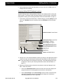
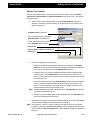
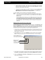
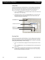
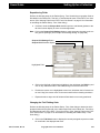
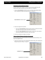
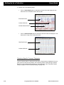
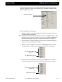
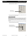
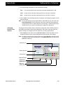
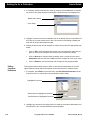
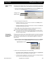
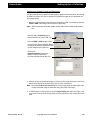
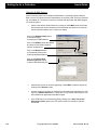
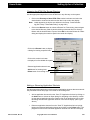
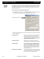
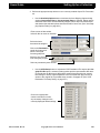
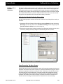
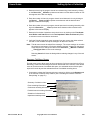
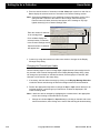
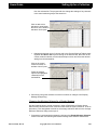
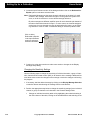
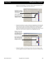
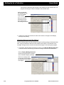
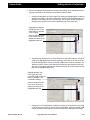
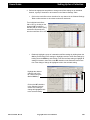
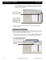
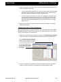
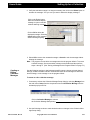
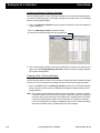
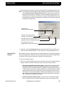
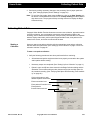
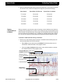
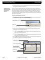
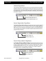
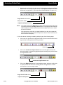
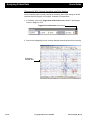
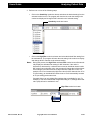
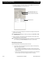
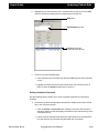
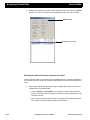
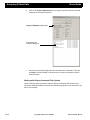
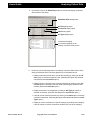
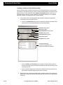
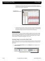
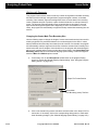
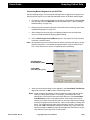
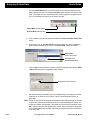
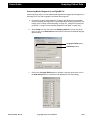
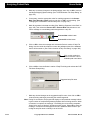
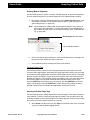
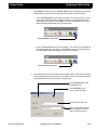
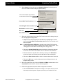
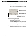
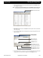
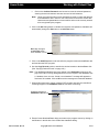
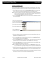
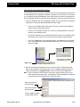
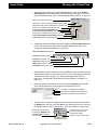
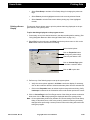
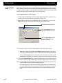
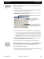
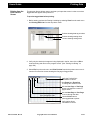
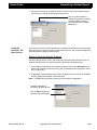
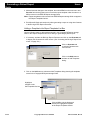
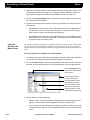
Setting Up for a Collection Users Guide new setting from the activated list. The program will change all settings to the selected value. Verify no channels are highlighted, then click on the LF or HF control button. Select the desired filter setting from the list to close the list and change all settings. 3. Continue by using other sections to make more entries or changes in the Display Montage Setup dialog. Changing the Notch Filter Settings Use the following steps to either attenuate the narrow band of frequencies centered around the notch filter frequency set at the factory (selected) or disable the option to prevent attenuation from occurring. This feature cannot be disabled during analysis if the Notch Filter option was activated during collection and the data was recorded as filtered. 1. If necessary, load the desired montage by clicking on the Display Montage Selection combo box button and selecting the desired montage name from the activated list. Click on Display Montage Selection combo box arrow button to activate a list of available display montages. Click on a montage name to close the list and display the selection in the combo box display. 2-68 Ceegraph Vision Users Manual 590-CGVUM1, Rev B Users Guide Setting Up for a Collection 2. Perform the appropriate step below to change notch filter settings on an individual channel, a group of channels or all channels in the Channel Settings Table. • Click on the notch filter column checkbox for any channel in the Channel Settings Table to either activate or de-activate a selection checkmark. Turn individual notch filters ON or OFF, by clicking on the channel’s NF checkbox to activate (ON) or remove (OFF) a selection checkmark and turn the notch filter ON or OFF. • Randomly highlight a group of unwanted notch filter settings by holding down the Ctrl key and clicking on the settings or highlight a series of notch filter settings by holding down the Shift key and clicking on the first and last setting to highlight all settings in between, then click on the NF checkbox in the Selected Controls section of the dialog to change all highlighted cells to the selected setting. Highlight the desired channel cells in the NF column using the Ctrl or Shift key. Click on the NF checkbox in the Selected Controls section of the dialog to change all highlighted cells to the selected setting. 590-CGVUM1, Rev B Ceegraph Vision Users Manual 2-69 Setting Up for a Collection • Users Guide Click on the NF checkbox control in the Selected Controls section of the dialog to activate or remove a selection checkmark and turn the Notch Filter ON or OFF respectively in all NF table cells. Verify none of the table cells in the NF column are highlighted before starting. Click on the NF control checkbox in the Selected Controls section of the dialog to change all NF table cell settings to the control checkbox setting. 3. Continue by using other sections to make more entries or changes in the Display Montage Setup dialog. Inverting the DC Channel Waveforms Use the following steps to invert selected DC channels on the program screen using table cell options in the Display Montage Setup dialog menu. Selections can be either saved to the current montage or used until exiting the program. 1. If necessary, load the desired montage by clicking on the Display Montage Selection combo box button and selecting the desired montage name from the activated list. Click on Display Montage Selection combo box arrow button to activate a list of available display montages. Click on a montage name to close the list and display the selection in the combo box display. 2-70 Ceegraph Vision Users Manual 590-CGVUM1, Rev B Users Guide Setting Up for a Collection 2. Locate the desired DC channel row(s) in the Channel Settings table display and perform the appropriate step below. • To invert individual DC channels: Click on the Op column table cell of the desired DC channel row to activate a list of available options. Click on Inv from the activated list to display the selection in the Op column table cell. • To invert several DC channels at the same time: Highlight the desired DC channels in the Channel Settings table, click on the - / Inv control box button in the Selected Controls section of the dialog and select the Inv option from the activated list to display the new selection in the Op column table cell of each highlighted channel. 3. Continue by using other sections to make more entries or changes in the Display Montage Setup dialog. Changing the Color of Channel Waveforms Use the following steps to change the waveform color of channels listed in the Display Montage Setup dialog. Dialog features allow users to change waveform colors individually, as a selected group or simultaneously. 1. If necessary, load the desired montage by clicking on the Display Montage Selection combo box button and selecting the desired montage name from the activated list. Click on Display Montage Selection combo box arrow button to activate a list of available display montages. Click on a montage name to close the list and display the selection in the combo box display. 2. Perform the appropriate step below to change the waveform color of an individual channel, a group of channels or all channels in the Channel Settings Table. 590-CGVUM1, Rev B Ceegraph Vision Users Manual 2-71 Setting Up for a Collection • Users Guide Highlight an undesired channel waveform color in the Color column of the Channel Settings table and select a new color from the activated color palette. Click on the undesired channel color to highlight it and select a new color from the activated palette. • Highlight a group of individual channel waveform colors by holding down the Ctrl key and clicking on each unwanted channel color before selecting the desired color from the last activated color palette. Highlight a group of channel waveform colors in a series by holding down the Shift key, clicking on the first and last color in the series and selecting the desired waveform color from the last activated palette. Highlight unwanted channel colors randomly or in a sequence. Click on the desired channel color in the last activated palette to change all highlighted channels to the selected color. • 2-72 Click on the Color column heading in the Channel Settings Table to highlight all color cells in the column, then click on the Color combo box button in the Selected Ceegraph Vision Users Manual 590-CGVUM1, Rev B Users Guide Setting Up for a Collection Controls section of the dialog and click on the desired color from the activated color palette. Highlight all channel color cells by clicking on the Color column heading. Click on the Color control box and select a new color from the activated palette to change all cells to the selected color. 3. Continue by using other sections to make more entries or changes in the Display Montage Setup dialog. Saving a Montage as the Program Default Use the following steps to save a currently selected display montage as the program default. Once selected, the system will automatically load the montage each time the program is entered. In cases where a new display montage is being saved as the default and there isn’t a montage file, the program will also save the average references as the default at the same time 1. If necessary, load the desired montage by clicking on the Display Montage Selection combo box button and selecting the desired montage name from the activated list. Click on Display Montage Selection combo box arrow button to activate a list of available display montages. Click on a montage name to close the list and display the selection in the combo box display. 590-CGVUM1, Rev B Ceegraph Vision Users Manual 2-73 Setting Up for a Collection Users Guide 2. Verify all dialog options and settings are correct, then click on the Default button in the Display Montage Selection section to activate a message indicating the selected montage has been "set" as the default. Click on Default button to activate a message indicating the display montage was set as the program default. Click on OK to close the message and start using the display montage as the program default. 3. Select OK to close the message and begin using the selected montage as the program default. Deleting an Unwanted Display Montage Use the following steps to delete unwanted or outdated montages from the Display Montage Selection combo box list in the Display Montage Setup dialog. 1. If necessary, load the desired montage by clicking on the Display Montage Selection combo box button and selecting the desired montage name from the activated list. Click on Display Montage Selection combo box arrow button to activate a list of available display montages. Click on a montage name to close the list and display the selection in the combo box display. 2-74 Ceegraph Vision Users Manual 590-CGVUM1, Rev B Users Guide Setting Up for a Collection 2. Verify the selected montage is no longer necessary, then click on the Delete button to activate the message: "Are you sure you want to delete this display montage?" Click on the Delete button while the unwanted display montage is open to activate a deletio warning message. Click on OK to delete the displayed montage. Selecting Cancel will exit the message without deleting anything. 3. Select OK to remove the unwanted montage or Cancel to exit the message without deleting the montage. Note: The program can not delete a montage saved as the program default. To remove a default montage, first save another montage as the default and then perform steps 1 through 3. (See “Saving a Montage as the Program Default” on page 73.) Creating or Editing Collection Montages Use the following sections to load alternate amplifier setups, change selected channel settings, enable or disable collection channels and save the new changes to either the same montage, a new montage or as the program default. To create or edit a collection montage: 1. If necessary, activate the Collection Montage Setup dialog by selecting Montage from the main menu, Setup from the drop-down menu and Collection Montage from the activated pop-up menu list. Click on Collection Montage to activate the Collection Montage Setup dialog. 2. Use the following sections to make desired entries or changes in the Collection Montage Setup dialog. 590-CGVUM1, Rev B Ceegraph Vision Users Manual 2-75 Setting Up for a Collection Users Guide Loading an Alternate Collection Montage Use the following steps to load an alternate montage into the Collection Montage Setup for viewing or editing purposes. The loaded montage can be saved under a new montage name or as the program default. 1. Click on the Montage Selection combo box button to activate a list of all available collection montages. Click on the Montage Selection combo box button and select the desired montage from the activated list. 2. Click on the desired montage name in the activated list to close the list, enter the montage name in the Display Montage Selection combo box and all montage settings in the Channel Settings table. Creating a New Collection Montage. Use the following steps to create a new collection montage with desired amplifier settings for future use. Once created, new montage can also be saved as the program default. 1. Click on the New button in the Montage Selection section of the Collection Montage Setup dialog to clear the combo box display and change all amplifier settings to the program default. Note: The program will automatically display a warning message: "Collection montage has been modified. Select Yes to save changes. Select No to abandon changes" if the above step is performed before all changes to the montage have been saved. Continue by selecting either Yes to save the changes to the previous montage name, No to abandon the changes or Cancel to return to the Collection Montage Setup screen without saving or abandoning any of the changes. 2-76 Ceegraph Vision Users Manual 590-CGVUM1, Rev B Users Guide Setting Up for a Collection 2. Enter a unique collection montage name at the activated cursor in the Montage Selection combo box display, then make any desired changes to the Channel Settings table. Click on New to clear the Montage Selection Combo box and change all amplifier settings to the default. Enter the desired montage name at the activated cursor. 3. Select Save to save the default settings to the entered montage name, then use the following sections to make any desired changes to the montage. Changing the Low Filter Settings in a Collection Montage. Use the following steps to change the low filter settings assigned to channel(s) in a collection montage anytime alternate filter settings are available for the hardware in use. If available, users can simultaneously change all low filter channel settings, a selected group of low filter settings or an individual low filter setting as desired. 1. Verify the correct collection montage name appears in the Montage Selection combo box display, changing if necessary. 2. If available, perform the appropriate step below to change the low filter setting(s) on an individual channel, a group of channels or all channels in the Channel Settings Table display. 590-CGVUM1, Rev B Ceegraph Vision Users Manual 2-77 Setting Up for a Collection • Users Guide Change the low filter setting for an individual channel by clicking on the low filter table cell to activate a list button, clicking on the button to activate a list of available settings and then clicking on the setting to display it in the table cell. Highlight the unwanted setting and click on the activated arrow button to display a list of available settings. Select the desired setting to close the list and enter the setting in the table cell. • Highlight the desired group of Low Filter table cells in the Channel Settings Table using the Ctrl or the Shift key, then click on the combo box button in the last selected cell and select a new setting from the activated list to change all highlighted settings. Highlight the desired low filter table cells using the Ctrl or Shift key, then click on the combo box button to display a list of settings. Select the desired setting to close the list to enter the setting in all table cells. 2-78 Ceegraph Vision Users Manual 590-CGVUM1, Rev B Users Guide Setting Up for a Collection • Click on the LF control box button in the Selected Electrodes section while none of the cells in the Channel Settings table are highlighted, then select the desired setting from the activated list to change all highlighted to the selected value. Click on the LF control box button while none of the table cells are highlighted to activate a list of available settings. Select the desired setting from the activated list to enter the setting in all cells that can be changed. 3. Continue by making other desired changes in the Collection Montage Setup dialog. Changing the Collection Montage Input Ranges Use the following steps to change peak to peak voltage input range of a selected channel to an alternate voltage input range. Changing the input range in one or more Channel Settings Table cells will automatically change the input range of all channels in the same hardware group. 1. If necessary, activate the Collection Montage Setup dialog and verify the correct montage name appears in the Montage Selection combo box display before continuing. 2. Click on the desired channel cell in the Input Range column of the Channel Settings Table to activate a button. Highlight an Input Range cell and click on the cell button to display a list of ranges. Select a range from the list to display it in all channels in the same hardware group. 590-CGVUM1, Rev B Ceegraph Vision Users Manual 2-79 Setting Up for a Collection Users Guide 3. Click on the button to display a list of all available input range settings. 4. Select the desired setting to close the list and change all channels in the same hardware group to the selected input range. Note: Changes made to individually configurable Netlink Traveler channels will only apply to the channel being changed. 5. Continue by making other desired changes in the Collection Montage Setup dialog. Enabling or Disabling a Montage Channel. Use the following steps to add or remove channels from a collection montage. The amount of channels in this table will be dependent on the amplifier options as well as the type of patient connection in use. The program will automatically add or remove the appropriate electrodes from the Electrodes (View Only) panel as users enable or disable channels in the Channel Settings Table. 1. Verify the correct montage name appears in the Montage Selection combo box display, changing if necessary. 2. Use the following steps to enable or disable individual channels, a group of channels or all channels in the Channel Settings Table. • Enable or disable an individual channel by clicking on the checkbox in the Enable column of any channel in the Channel Settings Table to enable (checked) or disable (unchecked) the channel. Click on a checkbox to enable (checked) or disable (unchecked) the selected channel. Disabled channels will appear shaded. Click on the En checkbox to enable or disable all channels at once. 2-80 • Enable or disable channels in random order by holding down the Ctrl key and clicking on the desired checkboxes in the Enable column to either enable the selected channels (checked) or disable them (unchecked). • Enable or disable a channels in sequential order by holding down the Shift key and clicking on the first and last checkbox in the Enable column to either enable all channels in between (checked) or disable them (unchecked). • Enable or disable all channels at once by clicking on the En control checkbox in the Selected Electrodes section of the dialog to enable all channels (checked) or disable all channels (unchecked). Ceegraph Vision Users Manual 590-CGVUM1, Rev B Users Guide Setting Up for a Collection 3. Continue by making other desired changes in the Collection Montage Setup dialog. Renaming Channel Electrodes Use the following steps to rename any channel electrode being displayed in the Electrodes (view only) section of the Collection Montage Setup. 1. Highlight the unwanted electrode name in the Name column of the Channel Settings Table and enter the desired electrode name in its place. Highlight the unwanted electrode name and enter the desired electrode name in its place. 2. Repeat the above step as often as necessary until all electrodes have the desired names. 3. Continue by making other desired changes in the Collection Montage Setup dialog. Saving the Collection Montage as the Program Default. Use the following steps to save any collection montage as the program default. Once saved, the program will automatically load the collection montage settings each time Ceegraph Vision is entered. 1. If necessary, load the desired collection montage by clicking on the Montage Selection combo box button and selecting the desired montage from the activated list to enter it in the combo box display. 2. Verify all amplifier settings in the Channel Settings Table are correct, changing if necessary. 3. Click on the Default button to activate the message: “Collection montage has been set as the default collection montage.” 4. Click on OK to close the message and save the montage as the program default. The program will automatically load the montage each time it is launched. 590-CGVUM1, Rev B Ceegraph Vision Users Manual 2-81 Pre-collection Activities Users Guide Deleting a Collection Montage. Use the following steps to delete unwanted collection montages. This feature can not be used to delete a montage that has been saved as the program default. Default montages can only be deleted by saving another montage as the default first. 1. Load the unwanted montage by clicking on the Montage Selection combo box button and selecting the montage from the activated list. 2. Verify the correct montage is being displayed, then click on Delete to activate the message: "Are you sure you want to delete this collection montage?". 3. Select OK to delete the unwanted collection montage. Notes: Selecting Cancel will exit the message without performing the deletion. The program cannot delete a collection montage that has been saved as the program default. To remove a default collection montage, first save another montage as the default and then perform the above steps to delete the unwanted montage. Pre-collection Activities Performing a Manual Calibration Although Ceegraph Vision automatically calibrates the headbox amplifiers during start up, users can also perform a manual calibration to ensure the all amplifiers are performing correctly. To perform a manual calibration: 1. Select Tools from the main menu and Calibrate Amplifiers from the drop-down menu to display “Calibrating Amplifiers” in the message area and start calibrating the system headbox. 2. Allow the program to complete calibration and display the message: “Calibration Completed” in the message area of the screen before continuing. 2-82 Ceegraph Vision Users Manual 590-CGVUM1, Rev B Users Guide Pre-collection Activities c. Select Display from the main menu and Calibration Results from the drop-down menu to review the calibration results table on the program screen. Calibration Results for each channel in the display montage Select the OK button to exit the dialog Note: The program will automatically display a warning message and highlight any channel row with unacceptable calibration results. If re-calibration does not bring the desired results, run the headbox diagnostics program and call Customer Support with the results. (See “Customer Support” on page 8.) Viewing Calibration Signals Ceegraph Vision allows users to disable the patient electrode input from the system headbox and display a square wave calibration signal using the frequency and amplitude specified in the Calibrator Signal Settings dialog. Since Ceegraph Vision automatically calibrates the headbox whenever Ceegraph is entered, viewing calibration signals or recording them to the beginning of a collection is optional. To view headbox calibration signals: 1. If necessary, load a referential montage with a system reference on the program screen, then verify the correct amplitude and frequency are selected in the Calibrator Signal Settings dialog before starting. (See “Creating and Saving a New Display Montage” on page 61 and the “Calibrator Signal Settings Dialog” on page 274) 2. Click on the View Only toolbar button or select View from the main menu and View only (data not saved) from the drop-down menu to display incoming signals on the program screen. 3. Click on the Calibration Signals toolbar button or select View from the main menu and Calibration Signals from the drop-down to begin displaying calibration signals on the program screen. 4. If necessary, adjust the amplifier or display settings until the signals are correct, then reselect the Calibration Signals toolbar button to toggle it OFF unless the signals are being recorded to the beginning of the collection. 590-CGVUM1, Rev B Ceegraph Vision Users Manual 2-83 Pre-collection Activities Users Guide 5. Exit View Mode by selecting File from the main menu and Stop Viewing from the drop-down menu or clicking on the Stop Viewing toolbar button. Calibrating External Devices on DC Channels Prior to a Collection If desired, users can calibrate an external device for a specific DC channel in order to display the incoming numeric values on the channel display. This type of calibration can only be performed if there is a steady input signal and is only necessary if it’s important for DC numeric values to appear in the channel display. To calibrate an external device on a DC channel: 1. If necessary, load the appropriate DC Channel montage and start a patient collection before continuing. (See “Creating and Saving a New Display Montage” on page 61 and “Starting a Collection” on page 91.) 2. Highlight the label of the DC channel requiring a numeric value display; set the external DC device to low calibration mode and perform one of the following steps. • Click on the DC Cal toolbar button and select Enter Low DC Calibration Value from the pop-up menu list to activate the DC Calibration Data Entry Menu dialog. Activated toolbar drop-down menu DC Cal toolbar Button Click on the Enter Low DC Calibration Value option • Select Tools from the main menu, DC Calibration from the drop-down menu, and Enter Low DC Calibration from the drop-down menu to activate the DC Calibration Data Entry Menu dialog. Replace the highlighted value with the desired value Leave blank Click on OK to exit dialog 3. Enter the desired calibration value in the Low Calibration Value text box and select OK without making an entry in the Data Units text box. 2-84 Ceegraph Vision Users Manual 590-CGVUM1, Rev B Users Guide Pre-collection Activities 4. Set the external DC device to high calibration mode and perform one of the following steps. • Click on the DC Cal button and select Enter High DC Calibration Value from the pop-up menu list to activate the DC Calibration Data Entry Menu dialog. • Select Tools from the main menu, DC Calibration from the drop-down menu and Enter High DC Calibration from the pop-up menu to activate the DC Calibration Data Entry Menu dialog. 5. Enter the desired value in the High Calibration Value dialog box and select OK without making any entry in the Data Units text box. Replace the highlighted value with the desired value Leave blank Click on OK to exit dialog 6. When the DC Calibration Results confirmation dialog appears, review the entered calibration values and then select OK to return to the DC Calibration screen. Note: If the DC Calibration Results confirmation dialog doesn’t appear on the screen, the calibration is not complete and must be performed again. 7. Click on the DC Cal button and select Quit from the pop-up menu list; or select Tools from the main menu, DC Calibration from the drop-down menu and Quit from the pop-up menu to exit the dialog. 590-CGVUM1, Rev B Ceegraph Vision Users Manual 2-85 Pre-collection Activities Users Guide 8. Review a summary of all calibrations, by selecting Display from the main menu and DC Calibration Results from the drop-down menu then select OK to exit the dialog. Summary of all channel calibrations Click on OK to exit the Calibration Summary window Entering Patient Information & a Test ID Because Ceegraph Vision permanently stores the patient’s name with each data collection file, users must enter a patient name and patient ID before starting a collection. If desired, users can also store additional patient and test information to the patient file using features in the P&TI database program. To add patient information and a test ID number to a file: 1. Select File from the main menu and New Recording from the drop-down menu to activate the Begin Collection dialog on the program screen. Enter test number here Enter patient ID number here Enter patient’s first and last name here 2-86 Ceegraph Vision Users Manual 590-CGVUM1, Rev B Users Guide Pre-collection Activities 2. Enter the patient’s last name, first name and Patient ID in the appropriate text boxes. Note: The program will automatically activate a Matching Patient Record ID Found dialog if the Save, Record or Ready to Record button is selected and a file with an identical Patient ID number is entered in the P&TI database. Dialog options provide the option of entering a new Patient ID, using the existing Patient ID or viewing the previously existing recording before continuing. (See “Matching Patient ID Found Dialog” on page 294.) Has the same patient ID for both patients Use this button after entering entering a new patient ID Use this button to insert the patient information for the currently existing ID Use this button to exit the dialog without making any changes. 3. If desired, click on the Patient Info button to activate the P&TI Form View tab menu screen and enter additional patient or test information in the provided tab menus. () Selecting Test Options Users have the option of collecting data in a compressed format, automatically stripping a file, performing periodic collections, record and store patient movements on digital video, run spike & seizure detections and make changes to the sampling rate. To select recording test options: 1. Click on any of the following options in the Test Options section of the Begin Collection dialog to activate a selection checkmark and use the option during collection. 590-CGVUM1, Rev B • Record Compressed Data checkbox option - allows users to activate a SmartPack data compression program for compressing data as it is being collected. During this process, the optional software is capable of collecting and storing up to 2.5 times the normal amount of patient data without any loss of information. Other program features allow users to page through data recordings at a much faster rate and transmit compressed data over network and telephone lines in less time than it takes to transmit standard data files. This optional program is only selectable if SmartPack is installed on the system. • Periodic Collection checkbox option - allows users to record data at specific times or selected intervals. Program features allow users to collect data at the Ceegraph Vision Users Manual 2-87 Pre-collection Activities Users Guide same time every day for a selected amount of days, a specified number of times per hour for a selected number of hours or a specified number of minutes when the F2 keyboard key or Patient Event button is pressed. Additional features also allow users to test impedance at selected times during the collection. Users must verify the program has been setup for periodic collections before attempting to use this option. (See “Periodic Collection Setup Dialog” on page 301.) • AutoArchive checkbox option - allows uses to automatically archive (or copy) previously un-archived data files from the collection drive(s) to a user specified drive at the beginning of a collection, during a cascade and at the end of a collection, provided the parameters and software criteria entered in the Setup AutoArchive dialog have been met. (See “Setup AutoArchive Dialog” on page 307.) • AutoStrip checkbox option - tells the program to automatically strip each file whenever the recording stops or cascades to a new file. During this process the program will display an Automatic Stripping dialog showing the number and segment of the file being processed and the percentage completed. • Digital Video (MPEG) checkbox option - allows users to create a digital video recording while the system is collecting data. The program will automatically synchronize incoming video data with the incoming data signals to ensure accurate viewing. Once the data has been saved to a disk, users can view the data and video recordings individually or at the same time. • Spike/Seizure Detection checkbox option - allows users to activate an installed Spike/Seizure Detection program from the Begin Collection dialog. It is only available if Spike/Seizure Detection program is installed on the system and enabled for use. • Magic Marker checkbox option - allows users to automatically start a Magic Marker Analysis at the beginning of a collection, provided MagicMarker software is installed on the system. During this process the MagicMarker program will analyze data as it becomes available. It will also open, close and cascade to a new file whenever collection files are opened, closed and cascaded. Test Options Sample Rate Options 2-88 Ceegraph Vision Users Manual 590-CGVUM1, Rev B Users Guide Pre-collection Activities 2. If necessary, change the sample rate being used by clicking on the desired rate in the Sample Rate (Hz) section of the dialog to activate a selection bullet. Note: Sample Rate options automatically reflect the type of amplifier being used and may not be available for some boxes. For example, systems with a 32 channel headbox (Gamma), a 128 channel headbox (XL), a 44 channel headbox (Netlink) or 16 to 32 channel amplifier (Netlink Traveler) can use sample rates of 256 Hz or 512 Hz, while systems with a 132 channel headbox (XL2) use sample rates of 256 Hz, 512 Hz or 1024 Hz. Verifying Disk Space and Recording Time Availability To avoid problems, verify the Estimated Recording Time text box in the Begin Collection dialog shows enough time and disk space to run the intended collection. In cases where the system hard drive doesn’t have enough disk space, remove unnecessary files from the collection drive before starting. (See “Deleting Patient Records” on page 170.) Estimated Recording Time and Disk Space Running an Impedance test If desired, users can run an impedance test from the Begin Collection dialog before starting a collection. During this process the program will measure and compare incoming electrode impedance values against the impedance limit specified in the Impedance Limit Settings dialog and display all values within the specified limits in GREEN or BLACK text and all values outside the limits in RED. To perform an impedance test: 1. Click on the Impedance button in the Begin Collection dialog or press the Impedance button on the Netlink headbox to activate an Impedance Results dialog and begin testing. 2. Verify all impedances are satisfactory, re-applying or replacing electrodes as needed until the results are satisfactory. Notes: 590-CGVUM1, Rev B The Impedance Results dialog will automatically display electrode impedances that are within the limits entered in the Impedance Limit Settings dialog in GREEN text (default color) and impedances that exceed those limits in RED Ceegraph Vision Users Manual 2-89 Pre-collection Activities Users Guide text. The program will automatically re-measure impedances every 18 seconds (time approximate). (See “Impedance Results Dialog” on page 291.) Passing impedances are displayed in Green Click on Close to stop the impedance test and exit the dialog To change the impedance limits used by the Impedance Results dialog, select Setup from the main menu and Impedance Limits from the drop-down menu. (See “Impedance Limit Settings Dialog” on page 291.) Currently selected Impedance Limit 3. Click on the Close button at the bottom of the Impedance Results dialog or press the Impedance button on the Netlink headbox to close the dialog and save all test results. Previewing Patient Data If desired, users can view patient data and make necessary changes to screen settings from the Begin Collection dialog before recording patient data to a file. The program will automatically display a red warning message in the program status bar indicating the displayed data is not being saved to a disk. To view patient data before starting a collection: 1. Click on the View Only button in the Begin Collection dialog to exit the dialog and begin scrolling unsaved data across the program screen. 2-90 Ceegraph Vision Users Manual 590-CGVUM1, Rev B Users Guide Collecting Patient Data 2. Continue by making necessary changes to the sensitivity, filter or paper speed settings. (See “Changing Display Screen Settings” on page 96.) Note: To exit View Only mode, either press the Esc key, click on the Stop Viewing toolbar button or select File from the main menu and Stop Viewing from the activated drop-down menu. The program will stop scrolling data and re-display the Begin Collection dialog. Collecting Patient Data Ceegraph Vision Netlink Traveler allows users to start a new collection, append/overwrite a previous collection, pre-record patient movements, add calibration signals to the recording, archive data at selected intervals, view previously collected data in a separate window, display data trends, perform photic/hyperventilation tests, view patient movements on the screen, and enter comments into the data. Starting a Collection Users can start a new patient collection after the appropriate setup and pre-collection activities have been performed. (See “Setting Up for a Collection” on page 11 and “Precollection Activities” on page 82. To start a new patient collection: 1. Verify the following procedures have been performed before continuing. • All hardware and patient equipment have been properly connected to the system and/or patient before starting. • Necessary setups are completed. (See “Setting Up for a Collection” on page 11.) • Patient’s name and ID have been entered in the Begin Collection dialog and the Estimated Time and Recording text box shows enough time and disk space for the intended recording. (See “Verifying Disk Space and Recording Time Availability” on page 89.) Click on this button to add additional patient information. Enter test number here. Enter patient ID number here. Enter patient’s first and last name here. 590-CGVUM1, Rev B Ceegraph Vision Users Manual 2-91 Collecting Patient Data Users Guide • All test options have been selected. (See “Selecting Test Options” on page 87.) • An impedance test has been performed and all results are satisfactory. (See “Running an Impedance test” on page 89.) • Patient data was pre-viewed and changes to sensitivity, filter and paper speed settings have been made. (See “Changing Display Screen Settings” on page 96.) 2. Click on Record to start collecting data. Note: If desired, continue by recording calibration signals or patient movements to the beginning of the collection for use during analysis. (See “Recording Calibration Signals at the Start of a Collection” on page 92 and “Recording Patient Movements at the Start of a Collection” on page 93.) Recording Calibration Signals at the Start of a Collection Use the following steps to disable patient electrode inputs and record calibration signals at the start of a recording. Square wave calibrations can only be produced if a referential montage with an appropriate sensitivity is being used. 1. If necessary, load a referential montage and verify all necessary collection setups and pre-collection activities are complete before continuing. (See “Display Montages Dialog” on page 283, “Setting Up for a Collection” on page 11 and “Pre-collection Activities” on page 82.) 2. Click on Record to exit the Begin Collection dialog and begin recording data. 3. Verify the Sensitivity toolbar combo box in the Settings toolbar displays an appropriate setting, such as a sensitivity of 10 for a 100 UV input. (See “Sensitivity Toolbar Combo Box” on page 5.) Sensitivity combo box set at 10 uV/mm 4. Click on the Calibration Signals toolbar button or select View from the main menu and Calibration Signals from the drop-down menu to start displaying square wave calibration signals on the program screen. Calibration toolbar button 2-92 Ceegraph Vision Users Manual 590-CGVUM1, Rev B Users Guide Collecting Patient Data 5. Collect the desired amount of calibration signals, then re-select the Calibration Signals toolbar button or menu option to stop displaying square wave calibration signals. 6. If necessary, change montages by clicking on the Select Display Montage toolbar button and selecting the desired montage from the Display Montages dialog. Default Montage List of available montages Recording Patient Movements at the Start of a Collection Use the following steps to record patient movements at the beginning of a recording. If desired, insert either a keyboard comment or a predefined comment to describe each movement. (See “Entering Collection & Event Comments” on page 103.) 1. If necessary, complete all collection setups, activate the Begin Collection dialog and make all necessary entries and selections before continuing. (See “Setting Up for a Collection” on page 11 and “Pre-collection Activities” on page 82.) 2. Click on the Record button in the Begin Collection dialog to start recording incoming patient data. Note: A matching Patient ID Found dialog will automatically appear anytime the patient’s ID is already entered in the system database. If this should occur, either use the ID and corresponding information stored in the database or enter a new ID.(See “Matching Patient ID Found Dialog” on page 294.) 590-CGVUM1, Rev B Ceegraph Vision Users Manual 2-93 Collecting Patient Data Users Guide 3. Use the Comment Toolbar to enter a predefined or keyboard comment as the patient performs each requested movement. (See “Entering Collection & Event Comments” on page 103.) Predefined Comments Keyboard Comments Note: If necessary, pause or stop the recording at any time, using the button. Appending to a Collection or toolbar Users have the ability to add additional data to a previously recorded data file or a paused collection that is still being displayed on the program screen. When appending to a previous recording, users should ensure the Patient ID, test number and date are correct to avoid collecting data to the wrong file. To append to a currently displayed or pre-existing collection: 1. Perform the appropriate step below. 2-94 • For paused recordings, click on the Start Recording toolbar button, select File from the main menu and Start Recording from the drop-down menu or press the Start/Stop button on the Netlink headbox to activate an Append/Overwrite dialog on the program screen. • For previous recordings, load the desired file on the program screen and either click on the Start Recording toolbar button, select File from the main menu and Start Recording from the drop-down menu or press the Start/Stop button on the Ceegraph Vision Users Manual 590-CGVUM1, Rev B Users Guide Collecting Patient Data Netlink headbox to activate an Append/Overwrite dialog on the program screen. (See “Loading a Data Recording” on page 122.) Append dialog option Estimated Recording Time text box OK button 2. Click on Append to activate a selection bullet, then verify the Estimated Recording Time text box shows enough disk space and time to perform the desired collection. 3. Select OK to close the Append/Overwrite dialog and start collecting data from the last stopping point in the data recording. Overwriting a Collection If necessary, users can overwrite a previously recorded patient file that is no longer being displayed on the program screen, as well as a recording that has been paused during a collection. When overwriting a pre-existing file, users should ensure the selected file has the correct Patient ID, Test Number and Test Date to eliminate any chance of overwriting the wrong file. To overwrite a paused or pre-existing recording: 1. Perform the appropriate step below. 590-CGVUM1, Rev B • For paused recordings, click on the Start Recording toolbar button, select File from the main menu and Start Recording from the drop-down menu or press the Start/Stop button on the Netlink headbox to activate an Append/Overwrite dialog on the program screen. • For previous recordings, load the desired file on the program screen and either click on the Start Recording toolbar button, select File from the main menu and Start Recording from the drop-down menu or press the Start/Stop button on the Netlink headbox to activate an Append/Overwrite dialog on the program screen. (See “Loading a Data Recording” on page 122.) Ceegraph Vision Users Manual 2-95 Collecting Patient Data Users Guide 2. Click on Overwrite to activate a selection bullet, then verify the Estimated Recording Time text box shows enough disk space and time to perform the desired collection. Overwrite dialog option Estimated Recording Time text box OK button 3. Select OK to close the Append/Overwrite dialog and start collecting data from the beginning of the file, eliminating all previously recorded data in the process. Note: The program will only overwrite the last file when data has been collected in a multi-cascaded file sequence. In cases where the file is cascaded and a Persyst SpikeDetector file (SD) is present, the program will automatically display the message: "Spike Detection has been run on this collection. Overwrite will not be allowed." and prevent the file from being overwritten. Changing Display Screen Settings Users have the option of changing the sensitivity, filter and paper speed settings at any time during a collection, while the paging speed can only be changed during Lookback or if the collection is stopped. Information provided in these sections can also be used during Lookback or Analysis, provided the View as Recorded button is toggled to OFF. Changing the Sensitivity to Change Waveform Size Use the following steps to increase or decrease the size of incoming waveforms using the Sensitivity combo box in the Settings toolbar. Screen changes will remain until a new recording is started, the program is exited or, if the program is in Lookback, Review or Analysis Mode, the View as Rec button is toggled back to ON. 1. If the Lookback, Editing or Analysis screen is active, verify the View-as-Recorded toolbar button in the Settings toolbar is toggled to OFF before continuing. Sensitivity toolbar combo box button View as Recorded toolbar button toggled to OFF. 2. Perform the appropriate step below. 2-96 Ceegraph Vision Users Manual 590-CGVUM1, Rev B Users Guide Collecting Patient Data • Increase or decrease the size of an individual waveform by highlighting the desired waveform’s channel label, clicking on the Sensitivity toolbar combo box button and selecting the appropriate sensitivity setting from the activated list. List of Available Sensitivities Highlighted Channel Label • Increase or decrease the size of all M/C waveforms by verifying none of the waveform channel labels are highlighted, clicking on the Sensitivity toolbar combo box button and selecting the appropriate sensitivity setting from the activated list. Changing a Low Filter Setting Use the following steps to change the low filter setting of an individual channel or all M/C channels using the Low Filter combo box in the Settings toolbar. Screen changes will remain until a new recording is started, the program is exited or, if the program is in Lookback, Review or Analysis Mode, the View as Rec button is toggled back to ON. 1. If the Lookback, Editing or Analysis screen is active, verify the View-as-Recorded toolbar button in the Settings toolbar is toggled to OFF before continuing. Low Filter toolbar combo box button View as Recorded toolbar button toggled to OFF. 2. Perform the appropriate step below. 590-CGVUM1, Rev B Ceegraph Vision Users Manual 2-97 Collecting Patient Data • Users Guide Change the low filter setting for an individual channel by highlighting the desired waveform’s channel label, clicking on the Low Filter toolbar combo box button and selecting the appropriate filter setting from the activated list. List of Available Low Filter Settings Highlighted Channel Label • Increase or decrease the size of all M/C waveforms by verifying none of the waveform channel labels are highlighted, clicking on the Low Filter toolbar combo box button and selecting the appropriate filter setting from the activated list. Changing the High Filter Settings Use the following steps to change the high filter setting of an individual channel or all M/C channels using the High Filter combo box in the Settings toolbar. Screen changes will remain until a new recording is started, the program is exited or, if the program is in Lookback, Review or Analysis Mode, the View as Rec button is toggled back to ON. 1. If the Lookback, Editing or Analysis screen is active, verify the View-as-Recorded toolbar button in the Settings toolbar is toggled to OFF before continuing. High Filter toolbar combo box button View as Recorded toolbar button toggled to OFF. 2. Perform the appropriate step below. 2-98 Ceegraph Vision Users Manual 590-CGVUM1, Rev B Users Guide Collecting Patient Data • Change the high filter setting on an individual channel by highlighting the desired waveform’s channel label, clicking on the High Filter toolbar combo box button and selecting the appropriate filter setting from the activated list. List of Available High Filter Settings Highlighted Channel Label • Increase or decrease the size of all M/C waveforms by verifying none of the waveform channel labels are highlighted, clicking on the High Filter toolbar combo box button and selecting the appropriate M/C filter setting from the activated list. Changing the Notch Filter Setting Use the following steps to either enable the Notch Filter and attenuate the narrow band of frequencies centered around the notch filter frequency that was set at the factory or disable the Notch Filter to prevent attenuation from occurring. If data is collected with the Notch Filter enabled, it cannot be disabled during Analysis or Edit Mode. Changes made to the Notch Filter will remain until a new recording is started, the program is exited or, if the program is in Lookback, Review or Analysis Mode, the View as Rec button is toggled back to ON. 1. If the Lookback, Editing or Analysis screen is active, verify the View-as-Recorded toolbar button in the Settings toolbar is toggled to OFF before continuing. Notch toolbar button View as Recorded toolbar button toggled to OFF. 590-CGVUM1, Rev B Ceegraph Vision Users Manual 2-99 Collecting Patient Data Users Guide 2. Highlight the desired channel label and click on the Notch toolbar button to change the button to either Notch=In (Frequency turned ON) or Notch=Out (Frequency turned OFF). Note: Notch = Out (OFF) isn’t available during Lookback or Analysis if patient data was recorded as a disk filtered collection with the Notch Filter enabled. Notch Toolbar Button Highlighted Channel Label Changing the Paper Speed Use the following steps to select the number of seconds of data that will appear on the program screen at one time. Changes to this option will automatically change the size of epochs appearing on the program screen. 1. Click on the Paper Speed toolbar combo box button to activate a list of available paper speeds. List of available Paper Speeds 2-100 Ceegraph Vision Users Manual 590-CGVUM1, Rev B Users Guide Collecting Patient Data 2. Select an appropriate paper speed using the following chart. The program will display the selection in the combo box display and change the epoch size accordingly. Paper Speed Viewing Collected Data in Lookback Epoch Size in Full Screen Epoch Size in Lookback 7.5 mm/sec 40 seconds 20 seconds 15 mm/sec 20 seconds 10 seconds 20 mm/sec 15 seconds 8 seconds 30 mm/sec 10 seconds 5 seconds 60 mm/sec 5 seconds 3 seconds During a collection, users have the option of opening a second window on the bottom or right side of the raw data screen in order to view or edit previously recorded data from the same collection. During this process, the program will automatically activate the appropriate screen buttons for the window in use. Lookback isn’t available during photic stimulation, nor can it be opened until the program has collected an adequate amount of data. To activate Lookback window during a collection: 1. Perform one of the following steps to activate a Lookback window showing all previously recorded data in the current collection. • Select View from the main menu and Lookback from the drop-down menu to activate the Lookback window on the program screen. • Click on the Open Lookback toolbar button in the collection toolbar to activate the Lookback window on the program screen. Comment Window toolbar button Lookback toolbar button Window selection bar showing window is active Raw data screen Lookback Window Navigational toolbar buttons 590-CGVUM1, Rev B Ceegraph Vision Users Manual 2-101 Collecting Patient Data Users Guide 2. Perform any of the following steps. • Click on the View as Rec button to toggle it to OFF to make desired changes to the screen filter settings. (See “Changing Display Screen Settings” on page 96.) • Use the Navigation toolbar buttons to move through the data or locate a point of interest. (See “Using Navigation Buttons to Move through Patient Data” on page 114.) • Locate comments in the data by selecting the Comment Window button in the Standard toolbar to activate the Comment Position dialog. (See “Comment Position Dialog” on page 277.) • Change between the Lookback and raw data window by clicking on the inactive window to display a selection bar at the top of the newly activated window. • "Tile" the Lookback and Collection windows vertically or horizontally by changing the Lookback tiling selection in the Display Setup Options dialog.(See “Tiling Lookback Windows Vertically or Horizontally” on page 29.) 3. Close the Lookback window at any time by reselecting the Lookback menu option or toolbar button. Changing the Paging Speed in Lookback Use the following steps to change the number of pages displayed per second when viewing data in Lookback. This feature is also available during Review and Analysis Mode, but is not available in the collection screen. 1. If necessary, activate or change to the Lookback screen before continuing. (See “Viewing Collected Data in Lookback” on page 101.) 2. Click on the Paging Speed Control combo box button in the Navigation toolbar to activate a list of available paging speeds. Paging Speed Control combo box list in the Navigation toolbar 2-102 Ceegraph Vision Users Manual 590-CGVUM1, Rev B Users Guide Collecting Patient Data 3. Click on the desired paging speed to close the list and enter the selection in the combo box display. Note: Speeds appearing in this combo box list can be selected in the Display Setup Options dialog. (See “Display Setup Options Dialog” on page 283.) • Entering Collection & Event Comments Re-dock the Trend Options toolbar at its last docked position by double clicking on the toolbar title bar. Users can enter predefined, keyboard and event comments at any time during a collection using the Comments toolbar or the event push button feature. Comments inserted during collection can be viewed in the Lookback window or when the program is in Review or Analysis Mode, provided the appropriate comment categories have been checked in the Comments section of the Display Setup Options dialog or the Display Comments Filter section of the Comments dialog. (See “Display Setup Options Dialog” on page 283 and “Comments Dialog” on page 278) To enter a enter a predefined, keyboard or event comment during collection: 1. Perform the appropriate step below. • Insert a Keyboard comment into the data by either clicking on the Keyboard Comment button in the Comments toolbar or typing the first few letters of the comment to activate the Enter Keyboard Comment window. Enter the comment text into the window, then press the Enter key to insert the comment into the data. Note: Comment text must start with an alphabetical letter (A-Z or a-z) or a single digit number (0 to 9), but may contain different types of punctuation or symbols in the remaining text. Keyboard Comment toolbar button Activates an Enter Keyboard Comment window • Insert a predefined comment by clicking on a Comments toolbar button with the appropriate comment abbreviation. (See “Comments Definition Menu Dialog” on page 279 to change comment abbreviations or text.) Comment buttons for inserting predefined comment text 590-CGVUM1, Rev B Ceegraph Vision Users Manual 2-103 Collecting Patient Data • Users Guide Insert an event comment into the data by pressing the provided event button. Note: Depending on the headbox being used, systems may have one event button (Netlink Traveler and Gamma I Headboxes) or two event buttons (Netlink headbox). In cases where a Netlink headbox is being used, the program will automatically label the inserted event comment as Patient Event 1 or Patient Event II to indicate which event button was used. 2. If necessary, continue by inserting any additional comments into the data. Note: If desired, use the Lookback window to view comments that have been inserted into the data. (See “Viewing Collected Data in Lookback” on page 101 and “Comment Position Dialog” on page 277.) Performing a Photic Stimulation Test Users can perform a photic stimulation test during a collection using one of two previously setup automatic stimulation sequences or by selecting a stimulation rate in the Photic Rates combo box. During testing, the program will automatically enter a stimulation mark at the bottom of the waveform display each time a stimulation occurs. To perform a photic stimulation test: 1. Perform the appropriate step below. • Start an automatic stimulation sequence by clicking on Photic Auto 1 or Photic Auto 2 button in the Activations toolbar to insert a photic stimulation comment into the record and start a sequence of photic stimulations at pre-determined rates. Note: Automatic stimulation sequences can have a maximum of 30 steps with each step using values entered in the Photic Sequence Control Settings dialog. Selected values determine the frequency of stimuli presented to the patient (Rate), how long the stimuli are presented (Duration) and the amount of elapsed time between stimulation steps (Interval). (See “Setting up Photic Sequences” on page 35.) Photic Auto 1 toolbar button Photic Auto 2 toolbar button Stop Photic toolbar button Photic combo box drop-down menu list • Click on the Photic combo box button and select the desired stimulation rate from the activated combo box list to insert a photic comment into the record and start photic stimulation at the selected rate. 2. Allow the program to execute the selected stimulations for the required amount of time. If necessary, terminate the stimulations by clicking on the Stop Photic button. 2-104 Ceegraph Vision Users Manual 590-CGVUM1, Rev B Users Guide Performing a Hyperventilation Test Collecting Patient Data Users can mark patient hyperventilation at specific times during the collection using the Hyperventilation toolbar button. During this process, the program will automatically insert comments marking the hyperventilation and post hyperventilation time periods in the recording and display the amount of elapsed time since each period began. Elapsed times must be setup before performing a hyperventilation test. (See “Setting up Hyperventilation Times” on page 36.) To mark hyperventilation and post hyperventilation during a collection: 1. Click on the HV=OFF button in the Activations toolbar to toggle it to HV=ON, insert an HV Start comment into the recording and mark hyperventilation for the time entered in the Hyperventilation Settings dialog. Notes: Re-selecting the HV button will stop the timer early and toggle the button to HV=PST. HV toolbar button toggled to OFF 2. Allow the program to mark hyperventilation for the required amount of time. The program will insert a HV Stop comment into the data, then change the HV button to HV=PST and insert a HV post start comment into the data. 3. Allow the program to complete the post time hyperventilation period and insert a HV Post Stop comment into the data before continuing. Note: Re-selecting the HV button will stop the timer early and toggle the HV button to HV=OFF. Using the Program Stopwatch This program feature allows users to time events and other occurrences on the program screen without affecting ongoing program activities. Once enabled, users can move the window display to any location on the screen, stop and restart timing or completely start over as desired. The Stopwatch icon is designed to remain "on top" of other programs and can run up to a maximum of four days. Times appearing in this display will automatically reflect the number of hours, minutes and seconds the timer has been running and can not be stored for future use. To use the program stopwatch to time an event: 1. If necessary, click on the Stopwatch toolbar button or select View from the main menu and Stopwatch from the drop-down menu to activate the Stopwatch icon. Click here to start the timer and change the text to Stop Displays elapsed hours, minutes & Seconds Click here to clear the timer 590-CGVUM1, Rev B Ceegraph Vision Users Manual 2-105 Collecting Patient Data Users Guide 2. Click on the Start button to change the button display to Stop and begin tracking the amount of elapsed time in the Stopwatch display. 3. Click on the Stop button to stop the timer and display the current amount of elapsed time in the window display. Note: If necessary, click on Start to continue timing or Reset to clear the displayed time and start over. Using Trend Windows During a Collection Users can display a maximum of two Trend windows showing Heart Rate (Pulse) and/or Oximetry (SaO2) channel measurement trends during collection, analysis or lookback as defined in the Trend Windows Setup dialog. During collection, channel measurement trends will appear as graphical data bars moving across the Trend window display with each data bar representing a minimum and maximum signal measurement in the DC channel. As data appears in the Trend window, the accompanying text boxes provide the starting, ending and duration time of each bar at the window cursor as well as the minimum and maximum measurements. Trend window measurements reflect current trends and can not be saved to the patient file or retrieved after they exit the window. Additional features in Analysis and Lookback allow users to move to any point in the recording in order to display the corresponding data bar at the Trend window cursor, the associated measurements in the Cursor Min and Cursor Max text boxes along with the starting, ending and duration time of each data bar. (See “Working with Trend Windows During Analysis or Lookback” on page 163.) To view DC channel measurement trends: 1. Select View from main menu and Trend Window from the drop-down menu to activate the Trend Window display on the screen. Cursor Max text box Cursor Min text box Trend window display 2-106 Ceegraph Vision Users Manual 590-CGVUM1, Rev B Users Guide Collecting Patient Data 2. View from the main menu and Trend Options from the drop-down menu to activate a Trend Options toolbar for viewing minimum and maximum measurements as the mouse is moved over trend data. Minimum measurement appears here Maximum measurement appears here Name of channel being measured 3. Allow the program to collect, measure and display data in the Trend Window display(s), then perform any of the following steps. Using the Digital Video Window • Click on a data bar in the Trend Window display to show its minimum and maximum measurements in the window’s Cursor Min and Cursor Max text boxes. • Move the mouse over one or more data bars in the Trend window display to show changing measurements in the Min and Max lines in the Trend Options toolbar. • Change the Trend Options toolbar from a docked to a floating toolbar by doubleclicking on an open space in the toolbar. Conversely, dock the floating Trend Options toolbar in it’s last position by double-clicking on the toolbar title bar. During a digital video collection, users can activate a MPEG Video Window for displaying real time patient images that are synchronized to the incoming patient data signals provided the system camera is connected and turned ON. In addition, collection systems must have a Mpgator board and digital video software installed to use this feature. To view video data during a digital video collection: 1. Click on the Video Window toolbar button or select View from the main menu and Video Window from the drop-down menu to activate the MPEG video window. Note: The Digital Video (MPEG) option must be checked in the Test Options section of the Begin Collection dialog to use this feature. (See “Selecting Test Options” on page 87.) Click on the Video Window toolbar button to activate the video window. Activated video window 590-CGVUM1, Rev B Ceegraph Vision Users Manual 2-107 Collecting Patient Data Users Guide 2. Start the collection to view incoming video data along with the incoming data signals. (See “Starting a Collection” on page 91.) Deleting Digital Video Files After an Automatic Archive Users can remove unwanted digital video recordings after they’ve been automatically archived to a storage disk during a recording. Attempts to delete digital video files during the during an automatic archive will activate the message: "AutoArchiving is currently copying a file. Please try again when this operation is complete." Once deleted, the program will automatically change the status of the corresponding patient files to indicate the video files no longer exists. To delete unwanted digital video files: 1. Select Edit from the main menu and Delete Digital Video from the drop-down menu to activate a Delete Digital Video - Select Path dialog. Select Paths combo box OK button 2. Perform one of the following steps to enter the pathname label of the archive drive containing the unwanted digital video files. • Click on the Select Paths combo box button to select the pathname label of the archive drive from the activated list. • Click on the Select Paths combo box display and enter the pathname label of the archive drive at the activated text cursor. 3. Click on OK to close the Delete Digital Video dialog and activate a Select Patients dialog showing all database records with digital video files. Select All button Table column headings Selection buttons for Data recordings with digital video files Find button OK button 2-108 Ceegraph Vision Users Manual 590-CGVUM1, Rev B Users Guide Post collection Activities 4. Perform any of the following steps in the Select Patients dialog. • Click on the Select All dialog button to simultaneously highlight all database records. • Double click on any table column heading to sort all cells in the selected column in either ascending or descending numeric/alphabetical order. • Click on the selection button preceding an individual file or press down the Ctrl or Shift key to either select files randomly or in a sequence. • Click on the Find button to activate a Find dialog for locating data recordings with specific text or numbers in user selected fields. Find dialog for locating data recordings with specific text in user selected fields 5. Verify all files with unwanted digital video files have been highlighted, then click on OK to begin deleting the unwanted video files. Note: In cases where the digital video file hasn’t been archived, the program will automatically activate the message: "You are about to delete a video file without archiving it. This file will be permanently deleted." If this occurs, select either Yes to continue deleting the video file or No to stop the deletion process. Post collection Activities Archiving Patient Files Manually If desired, users can manually archive patient records to a selected storage disk from the P&TI database program instead of automatically archiving them during a collection. Program features allow users to exclude digital video files to save space, delete the original tests once they have been archived or retain them for additional use. Once archiving is complete, the program will automatically insert archive information into the P&TI -Table View and P&TI - Form View screens for reference purposes. To manually archive patient records to an archive disk. 1. If necessary, select File from the main menu and Open Recording from the dropdown menu to activate the P&TI database program in Table View mode. 590-CGVUM1, Rev B Ceegraph Vision Users Manual 2-109 Post collection Activities Users Guide 2. Verify the correct Path Name Label appears in the Location combo box display, then highlight the record(s) being archived in the table display. Location combo box Highlighted Files 3. Select File from the main menu and Archive Record from the drop-down menu or click on the Archive Records toolbar button to activate the File Archive dialog. Destination combo box Source text Box Exclude Digital Video checkbox option Delete Tests After Archive checkbox option 4. Verify the Path Name labels in the Destination combo box, Source text box and Destination Disk Label text box are correct before continuing. Note: The Destination Disk Label text box will appear ghosted unless the selected destination drive doesn’t have a Path Name label. If this should occur, click on the Destination Disk Label text box and enter a name label at the activated cursor. 5. Click on the Exclude Digital Video checkbox option to add or remove a selection checkmark and exclude or keep any digital video files with the archived recording. 6. Click on the Delete Tests After Archive checkbox option to activate or remove a selection checkmark and delete or retain the original tests after archiving. 2-110 Ceegraph Vision Users Manual 590-CGVUM1, Rev B Users Guide Post collection Activities 7. Click on OK to begin archiving the selected records. Notes: A message: "The database *:\*.* does not exist. Create a new database?" will appear on the screen anytime the selected drive doesn’t have a P&TI database. If this should occur, select Yes to close the message, create a new database and restart the archiving process. If necessary, select Cancel in the File Archive or Archive Progress dialog to exit the dialog without archiving any of the selected records. The program will archive the selected records and insert archive information in the P&TI - Table View screen as well as the P&TI - Form View screen. Reviewing Patient Data The following sections explain how to view patient data with or without the corresponding video data, page or scroll through the data, view the data surrounding a selected comment and enter additional comments into the data. Viewing Patient Recordings with or without Digital Video Use the following steps to view patient data prior to analysis with, or without, the accompanying digital video files. If desired, change the paging or scrolling speed to move through the data at the appropriate pace. 1. If necessary, load the desired patient recording, then use one of the following steps to activate or remove the video window from the program screen. (See “Loading a Data Recording” on page 122.) • Select View from the main menu and Video Window from the drop-down menu to activate or hide an MPEG Video Window for displaying video data.(This option is only active if video data was collected with the file being displayed on the screen.) • Click on the Video Window button in the Standard toolbar to activate or remove the MPEG Video Window for displaying video data. (This toolbar button is only active if video data was collected with the file being displayed on the screen.) Video Window toolbar button View Main Menu Option Video Window menu option Begin Scroll button Paging Speed Control box display Paging Buttons in Navigation toolbar 590-CGVUM1, Rev B Ceegraph Vision Users Manual 2-111 Post collection Activities Users Guide 2. Perform the appropriate step(s) below. • Click on the Begin Scroll button in the Navigation toolbar to begin scrolling through the data at the speed selected in the adjoining Adjust Scroll Speed slide bar. Use the accompanying Stop toolbar button to stop scrolling at any time. • Click on the Continuous Page Forward or Continuous Page Backward button in the Navigation toolbar to continuously page through the patient data at the paging speed displayed in the adjoining Paging Speed Control combo box display. Use the accompanying Stop toolbar button to stop continuous paging. • Click on the appropriate paging button in the Navigation toolbar to move forward or backward through the data in the specified increment each time the button is clicked. Loading Data Being Collected or Stored on a Remote System Use the following steps to load patient and video data being collected or stored on a different networked system for review, editing or analysis purposes. Once the data is loaded, review incoming data on the program screen or perform standard editing and analysis functions in the Analysis or Lookback window. Remote system drive paths must be entered in the Setup - Data Paths and Patient Setup - Defaults dialog before starting. 1. Ensure the Setup - Data Paths dialog and the Patient Setup - Defaults dialog have the correct entries before starting. (See “Setup - Data Paths Dialog” on page 306 and “Patient Setup - Defalts Dialog” on page 297.) 2. Select File from the main menu and Open Recording from the drop-down menu to activate the P&TI - Table View screen. Note: One or more warning messages will appear on the screen anytime data paths are not correctly set up or the database configuration file isn’t available. If this should occur, set up the required data paths and defaults in Step 1 before continuing. 3. If necessary, click on the Location combo box button and select the remote system’s pathname label from the activated list to enter it in the combo box display and show all database files in the screen table. Location combo box with activated list Selection button 2-112 Ceegraph Vision Users Manual 590-CGVUM1, Rev B Users Guide Post collection Activities 4. Double click on the selection button preceding the desired patient file to close the P&TI - Table View screen and display the selected file on the program screen. Viewing Data being collected on a remote system Use the following steps to view patient and video data as it is being collected on another networked system or a data file that has been saved to a remote system database. During collection, most of the standard Lookback functions will be available to review data that is already saved to a disk and data that is within one page of the live data. In some cases there may be a slight delay while the program verifies a cascade was performed on the remote system and starts reading the new file. 1. If necessary, load the file being collected on the remote system before continuing. (See “Loading Data Being Collected or Stored on a Remote System” on page 112.) Note: If video data is being recorded, but isn’t being displayed, click on the Video Window toolbar button to activate the MPEG Video Window with the video data. (See “Viewing Patient Recordings with or without Digital Video” on page 111.) 2. Perform the appropriate step below to review previously collected data or view live data at the end of the file. • Review previously collected data using the provided paging buttons or Begin Scroll button in the Navigation toolbar to move through the data. Pause during scrolling by clicking on the Stop toolbar button, then resume scrolling by re-selecting the Begin Scroll button. Note: The program will automatically start at the time the data was paused and update the file bar to reflect current conditions when scrolling is resumed. If the time becomes more than one page behind the incoming live data during a pause, the program will display a space between the position indicator and the end of the file bar to indicate the discrepancy in time. To move to the most recent page of EEG and video data, click on the far, right end of the File Bar. Paging buttons Begin Scroll button Stop button File Bar Most recent page of EEG & video data 590-CGVUM1, Rev B Ceegraph Vision Users Manual 2-113 Post collection Activities • Users Guide View live data as it is being collected by either clicking on the far, right end of the File Bar or by clicking on the Stop Collection comment in the Comment Position dialog. (See “Comment Position Dialog” on page 277.) Using Navigation Buttons to Move through Patient Data Use the following steps to scroll, page or move to a new section of the currently displayed data recording. An alternate method is to select a comment in the Comments dialog to display the comment and its surrounding data on the program screen. (See “Comments Dialog” on page 278.) 1. If necessary, activate the Navigation toolbar by clicking on the Navigation checkbox in the Toolbars tab menu screen of the Customize dialog to activate a selection checkmark. (See “Customize Dialog” on page 280.) 2. Use the following descriptions to use different paging and scrolling icons. Paging Speed Control Combo Box The Paging Speed Control combo box allows users to determine how fast the program will display data by entering the number of pages to be shown per second. For example, entering 3.0 p/s will display 3 pages of data per second. Paging Speed Control combo box Adjust Scroll Speed Slide Bar The Adjust Scroll Speed slide bar allows users to determine the speed at which the vertical scroll line will move through the patient data by clicking to the left (slower) or right (faster) of the current speed marker’s position. Begin Scroll toolbar button Adjust Scroll Speed marker 2-114 Ceegraph Vision Users Manual 590-CGVUM1, Rev B Users Guide Post collection Activities Continuous Paging Buttons The Continuous Paging buttons allow users to move continuously forward or backward through the patient file at a selected speed. Program features allow users to determine how many seconds of data will be displayed at one time by changing the paper speed in the Settings toolbar. (See “Changing the Paper Speed” on page 26.) These buttons are only available if the program is in Lookback, Analysis or Review Mode and are not available during a collection. Continuous Page Forward button Continuous Page Backward button Forward 1 Page and Back 1 Page Buttons The Forward 1 Page and Back 1 Page buttons allow users to move forward or backward a page at a time in the data. Users can also determine how many seconds of data the program will display at one time by changing the paper speed in the Paper Speed Control combo box. (See “Changing the Paper Speed” on page 26.) These toolbar buttons are only available if the program is in Lookback, Analysis or Review Mode and are not selectable during a collection. Forward 1 Page button Backward 1 Page button Forward 1/2 Page and Back 1/2 Page Buttons The Forward 1/2 Page and Back 1/2 Page toolbar buttons allow users to move forward or backward a 1/2 page at a time in the data. Users can also determine how many seconds of data the program will display on the screen by changing the paper speed in the Paper Speed Control combo box. (See “Changing the Paper Speed” on page 26.) These toolbar buttons are only available if the program is in Lookback, Analysis or Review Mode and are not selectable during a collection. Forward 1/2 Page button Back 1/2 Page button 590-CGVUM1, Rev B Ceegraph Vision Users Manual 2-115 Post collection Activities Users Guide Forward and Back 1 Second Buttons The Forward and Back 1 Second toolbar buttons allow users to move forward or backward one second in the data. Users can also determine how many seconds of data will be displayed on the screen by changing the paper speed in the Paper Speed Control combo box. (See “Changing the Paper Speed” on page 26.) These toolbar buttons are only available if the program is in Lookback, Analysis or Review Mode and are not selectable during a collection. Forward 1 Second button Back 1 Second button Forward 1 Frame and Backward 1 Frame Buttons The Forward 1 Frame and Backward 1 Frame toolbar buttons allow users to move 1/30 of a second forward or 1/30 of a second backward through digital video data. During this process the scroll cursor in the waveform display will automatically move the same distance in the EEG data. These toolbar buttons are only available if the program is in Lookback, Analysis or Review Mode and are not selectable during a collection. Back 1 Frame button Forward 1 Frame button Previous and Next File Buttons The Previous and Next File toolbar buttons allow users to move to the file that was recorded before or after the currently displayed file. These toolbar buttons are only available if the program is in Lookback, Analysis or Review Mode and are not selectable during a collection. Previous File button Next File button 2-116 Ceegraph Vision Users Manual 590-CGVUM1, Rev B Users Guide Post collection Activities Adding Comments to the Data Use the following steps to insert additional comments into the patient data while the program is in Lookback, Analysis or Review mode. The program will automatically insert the comments in line with the comment position marker that appears as a blue inverted arrow in the blank space above the waveform display area. 1. Perform the appropriate step below to insert a new comment. • Using the system mouse, insert a predefined comment into the data by clicking on any comment button in the Comment toolbar. Comment toolbar buttons • Using the system mouse, click on the Keyboard Comment button in the Comments toolbar to activate an Enter Keyboard Comment text box. Type the desired text at the activated text cursor and press Enter to insert the comment into the data. Comment text must start with an alphabetical letter (A-Z or a-z) or number (0-9), but the remaining text may contain any type of punctuation or symbols. Click on the Keyboard Comment toolbar button to activate the Enter Keyboard Comment text box • Using the system keyboard, type the first few letters of the comment text to activate an Enter Keyboard Comment text box showing the entered letters. Type the remaining comment text at the activated cursor, then press Enter to insert the comment into the data. Comment text must start with an alphabetical letter (A-Z or a-z) or number (0-9), but the remaining text may contain any type of punctuation or symbols. Enter Keyboard Comment text box showing first few letters of comment text 2. If necessary, continue by inserting additional comments into the data. 590-CGVUM1, Rev B Ceegraph Vision Users Manual 2-117 Post collection Activities Users Guide Reviewing Trend Window Data Use the following steps to review DC channel measurements during Analysis or Lookback in program trend windows. The displayed windows show the DC channel measurement trends as graphical data bars moving across the window display with each data bar providing a visual interpretation of the minimum and maximum measurements of a recorded DC channel signal, such as Heart Rate (Pulse) or Oximetry (SaO2). Moving to a specific point in the data recording will automatically display the corresponding data bar at the window cursor and its numerical measurements in the Cursor Min or Cursor Max text boxes. Additional trend window text boxes provide the starting, ending and duration times as well. 1. If necessary, activate the program Trend window(s) by selecting View from the main menu and Trend Window from the drop-down menu. Note: This option is only available when DC channels are being displayed on the program screen and one or both Trend windows have been enabled in the Trend Windows Setup dialog. (See “Trend Windows Setup Dialog” on page 312.) Pulse trend window SA02 trend window Selected point in the Data File Bar Graphical data bar DC Channel Measurements 2. Move to a specific point in the recording by clicking on the desired location in the data file bar. 3. Review the graphical data bars and DC channel measurements corresponding to the selected point in the data recording. 4. Continue by selecting other desired points in the data to view the DC channel measurements and trending patterns. Working with Digital Video Data 2-118 The following sections explain how to activate an MPEG video window to review video data, manually scroll forward and backward through the video data, scroll between selected points in the data, change the scrolling speed and use the digital video zoom feature. Although a video camera doesn’t need to be connected to the system during Ceegraph Vision Users Manual 590-CGVUM1, Rev B Users Guide Post collection Activities Review or Analysis, the video window can only be enabled if digital video software is installed on the system and video data was recorded with the patient data. Activating the MPEG Video Window Use the following steps to activate an MPEG video window for viewing patient video data during Review or Analysis Mode. 1. Click on the Video Window toolbar button or select View from the main menu and Video Window from the drop-down menu to activate the digital video window. Video Window toolbar button View Main Menu Option Video Window menu option 2. Continue by scrolling through or viewing selected points in the video data. (See “Manually Scrolling Through Video Data” on page 119 and “Scrolling Between Selected Points in the Video Data” on page 120.) Manually Scrolling Through Video Data Use the following steps during Review, Editing or Analysis to manually scroll forward and backward through the video data from any point in the data. Use additional program features to scroll between selected starting and ending points one or more times, change the scrolling speeds or enlarge video data for easier viewing. (See “Scrolling Between Selected Points in the Video Data” on page 120, “Changing Video Data Scroll Speeds” on page 121 and “Using Digital Video Data Zoom” on page 121.) To manually scrolling through video data: 1. If necessary, load the desired digital video/data file and bring up the MPEG Video Window before starting. (See “Loading a Data Recording” on page 122 and “Activating the MPEG Video Window” on page 119.) 590-CGVUM1, Rev B Ceegraph Vision Users Manual 2-119 Post collection Activities Users Guide 2. Click on the desired starting point in the patient data to move the scroll cursor to the selected location and display the corresponding video data in the Video window. Note: Data must be stationary when performing this step. 3. Hold down the left mouse button and perform the appropriate step below. • Manually scroll forward by "dragging" the mouse toward the right edge of the screen. The scroll cursor and video data will simultaneously move forward with the mouse. • Manually scroll backward by "dragging" the mouse cursor toward the left edge of the screen. The scroll cursor and video data will simultaneously move backward with the mouse. Scrolling Between Selected Points in the Video Data Use the following steps to scroll between two points in the video data. During this process, the program will automatically retain the last starting and ending points for video data replays. 1. If necessary, load the desired digital video/data file and bring up the MPEG Video Window before starting. (See “Loading a Data Recording” on page 122 and “Activating the MPEG Video Window” on page 119.) Scroll cursor located at starting point Begin Scroll toolbar button Stop toolbar button Adjust Scroll Speed icon 2. Click on the desired starting point in the patient data to move the scroll cursor to the selected location and display the corresponding video data in the Video window. Note: Data must be stationary when performing this step. 3. Click on the Begin Scroll toolbar button to begin scrolling through the patient and video data from the selected point. 4. Click on the Stop toolbar button to stop scrolling at any point in the data. 2-120 Ceegraph Vision Users Manual 590-CGVUM1, Rev B Users Guide Post collection Activities Changing Video Data Scroll Speeds Use the following steps to change the scrolling speed for faster visual review of patient events. In cases where the selected scroll speed is too fast to maintain the signal window display the program will stop scrolling data and display only the visual and audio data until a slower speed is selected. 1. If necessary, load the desired video/data file, bring up the MPEG Video Window and click on the desired starting point in the patient data to move the scroll cursor to the desired starting point. (See “Loading a Data Recording” on page 122 and “Activating the MPEG Video Window” on page 119.) 2. Click on the Begin Scroll toolbar button to start scrolling through the data at the currently selected speed. 3. Increase or decrease the scrolling speed by clicking to the right (increase) or left (decrease) of the speed marker in the Adjust Scroll Speed slide bar display. Begin Scroll toolbar button Speed Marker in Adjust Scroll Speed slide bar Using Digital Video Data Zoom Use the following steps to define an area for enlargement in the video window. Areas can be enlarged up to 3 x their normal size and then be proportionally reduced back to their original size. This feature is available during Collection, Analysis and Review. 1. If necessary, load the desired video/data file, bring up the MPEG Video Window and click on the desired starting point in the patient data to move the scroll cursor to the desired starting point. (See “Loading a Data Recording” on page 122 and “Activating the MPEG Video Window” on page 119.) 2. Click on the Zoom In button, position the mouse curser at the beginning of an area of interest, hold down the left mouse button and "drag" the mouse cursor to the opposite end of the area. 590-CGVUM1, Rev B Ceegraph Vision Users Manual 2-121 Analyzing Patient Data Users Guide 3. Release the left mouse button to display only the selected area in the video window display. Zoom In button enlarges an area up to 3x its size Pan button moves enlarged section in any direction Zoom Out button reduces enlarged data proportionally Zoom to 100% button changes the image back to its original state Note: Borders surrounding a selected area may change slightly to maintain the correct aspect ratio of the image, but the center of the defined area will remain in the center of the window. 4. Perform any of the following steps after the first enlargement. • Repeat the above steps to enlarge the video data two more times. • Click on the Pan button to depress it, then hold down the left mouse button and "drag" the video data in any direction to view other enlarged areas of the data. • Click on the Zoom Out button to reduce the enlarged data in the same proportions it was enlarged. • Click on the Zoom to 100% button to change the altered image back to its original state. Analyzing Patient Data Loading a Data Recording This program function allows users to load a previously existing file from the P&TI database program in order to analyze the data, strip segments to a separate file or create a report. To load an previously existing file from a P&TI database: 1. If necessary, clear currently displayed data from the program screen by selecting File from the main menu and Close Recording from the drop-down menu. 2. Select File from the main menu and Open Recording from the drop-down menu to activate the P&TI Table View screen. Note: One or more warning messages may appear on the screen if data paths have not been set up or a database configuration file isn’t available. If this should occur, set 2-122 Ceegraph Vision Users Manual 590-CGVUM1, Rev B Users Guide Analyzing Patient Data up the required data paths and defaults before continuing. (See “Setup - Data Paths Dialog” on page 306 and “Patient Setup - Defalts Dialog” on page 297.) Location combo box with drop-down list File selection button 3. Verify the correct pathname label appears in the Location combo box display. If necessary, click on the combo box button to select an alternate location from the activated list. Note: Pathname labels and data paths for remote systems must first be defined in the Patient Setup - Defaults and the Setup - Data Paths dialogs. (See “Setup - Data Paths Dialog” on page 306 and “Patient Setup - Defalts Dialog” on page 297.) 4. Double-click on the selection button preceding the desired patient file to load the associated data recording on the program screen. Viewing Data Being Collected on Another System This program feature allows users to view patient and video data being collected or stored on another networked system. During a remote collection, users can view data within a page of the live data and use most of the features provided in Lookback. To view data being collected or stored on a remote system: 1. Load the file being collected or stored from the remote system. The file will automatically open to the first page of the collection. (See “Loading Data Being Collected or Stored on a Remote System” on page 112.) 2. If necessary, toggle the MPEG Video Window toolbar button ON to activate a video window for viewing patient movements when digital video data is present. (See “Working with Digital Video Data” on page 118.) 3. View previously recorded data by performing the appropriate step below. • Move forward or backward through the recorded data by selecting the appropriate paging button in the Navigation toolbar. (See “Using Navigation Buttons to Move through Patient Data” on page 114.) Navigation toolbar paging buttons 590-CGVUM1, Rev B Ceegraph Vision Users Manual 2-123 Analyzing Patient Data • Users Guide Continuously scroll through the data at a selected speed by clicking on the Begin Scroll button and moving the speed marker in the Adjust Scroll Speed bar to the left (slower) or right (faster). (See “Adjust Scroll Speed Slide Bar” on page 114.) Begin Scroll toolbar button Stop toolbar button Adjust Scroll Speed slide bar Notes: If necessary, click on the Stop button to pause during scrolling, then start scrolling again by reselecting the Begin Scroll button. The program will automatically start scrolling from the point data was paused and update the file bar to reflect all current conditions. If the pause time is more than one page behind the live data, the program will automatically add a space between the position indicator and the end of the file bar to show the discrepancy. 4. View live data as it is being recorded by performing any of the following steps. • Click on the far, right side of the program file bar to move to the end of the recording and view incoming data as it is being recorded. Click Here • Click on the Continuous Page Forward button in the Navigation toolbar and allow the program to continuously page through the recording to the point live data is being added to the file. Continuous Page Forward button • Click on the Begin Scroll button in the Navigation toolbar, adjust the scroll speed to quickly scroll to the end of the recording and then change back to a normal scroll speed to view incoming live data. Begin Scroll Toolbar button Adjust Scroll Speed bar 2-124 Ceegraph Vision Users Manual 590-CGVUM1, Rev B Users Guide Analyzing Patient Data • Open the Comment Position dialog and click on the “Stop Collection” comment to move to the end of the recording. (See “Comment Position Dialog” on page 277.) Comment Position Dialog Stopped Collection comment Changing Sensitivity and Filter Settings During Analysis, Lookback or Review, users can quickly change the sensitivity and filter settings of individual or MC channels using toolbar control boxes on the program screen. Channels belonging to the same hardware group will automatically change to the selected setting at the same time. Changing Individual Channel Settings Use the following steps to quickly change the sensitivity and filter settings of individual channels in the waveform display area. Channels belonging to the same hardware group will automatically change to the selected setting at the same time. 1. Verify the View-as-Recorded toolbar button in the Settings toolbar is toggled to OFF before continuing. View as Recorded toolbar button 2. Perform the appropriate step below to highlight the channel(s) being edited. 590-CGVUM1, Rev B • Highlight a single channel by clicking on the label of the desired channel. • Highlight multiple channels in random order by holding down the Ctrl key and clicking on each desired channel label. Ceegraph Vision Users Manual 2-125 Analyzing Patient Data • Users Guide Highlight channels in a sequence by holding down the Shift key and clicking on the first and last channel label in the sequence. Highlighted label in waveform display area 3. Perform one or more of the following steps to change the sensitivity and filter settings of the selected channel(s). • Click on the Sensitivity combo box button and select the desired setting from the activated combo box list. The program will close the list, enter the setting in the combo box display and change the waveform size on the program screen. Sensitivity combo box button 2-126 Ceegraph Vision Users Manual 590-CGVUM1, Rev B Users Guide Analyzing Patient Data • Click on the Low Filter combo box button and select the desired setting from the activated list. The program will close the list, enter the new filter setting in the combo box display and change the low filter setting on the selected channel(s). Low Filter combo box button • Click on the High Filter combo box button to select a new filter setting from the activated list, enter the new filter setting in the combo box display and change the high filter setting on the selected channel(s). High Filter combo box button • Click on the Notch Filter toolbar button to toggle it to ON or OFF. Note: During Analysis, Lookback or Review, the Notch=OUT option is not available if the patient data was recorded in a disk filtered collection using the Notch=IN option. Notch Filter in/out button 590-CGVUM1, Rev B Ceegraph Vision Users Manual 2-127 Analyzing Patient Data Users Guide Changing All M/C Channel Sensitivity and Filter Settings Use the following steps to quickly change the sensitivity and/or filter settings of all M/C channels while the program is in Analysis, Lookback or Review Mode. 1. If necessary, click on the Toggle View-as-Recorded toolbar button in the Settings toolbar to toggle it to OFF. Toggle View as Recorded toolbar button 2. Remove the highlighting from all currently displayed channel labels before continuing. Highlighted channel label 2-128 Ceegraph Vision Users Manual 590-CGVUM1, Rev B Users Guide Analyzing Patient Data 3. Perform one or more of the following steps. • Click on the Sensitivity combo box button and select the desired setting from the activated combo box list. The program will close the list, enter the setting in the combo box display and change all M/C channels to the selected setting. Sensitivity combo box button • Notes: Click on the High Filter combo box button and select the desired filter setting from the activated list. The program will enter the new setting in the combo box display and change all M/C channels to the selected setting. During this process, the High Filter and Low Filter combo boxes will automatically display the standard filter setting for M/C channels. If the value is increased or decreased by a selected amount and an individual channel under M/C control has an alternate value, the program will change the individual channel’s settings by the same amount as other channels under M/C control. For example, if the user increases the High Filter value for M/C channels from 35 to 70 (one setting), an individual M/C channel set at 15 will automatically increase to 35 (one setting) at the same time. Ceegraph Vision can only display filter settings that are available for use. For example, if a file was collected with a high filter setting of 70, settings above that value (100) will not be available for use. High Filter combo box button 590-CGVUM1, Rev B Ceegraph Vision Users Manual 2-129 Analyzing Patient Data • Users Guide Click on the Low Filter combo box button and select the desired filter setting from the activated list. The program will enter the new setting in the combo box display and change all M/C channels to the selected setting. Low Filter combo box button • Note: Click on the Notch toolbar button to toggle it to Notch = IN (ON) or Notch = OUT (OFF). The program will change all M/C channels to the selected setting. The Notch=OUT setting is not available anytime data was recorded in a disk filtered collection using the Notch IN setting. Notch = IN / Notch = OUT Button Using the Program Editing Screen Editing screen features allow users to review, remove or enter additional comments into a data recording, measure voltages, view peak to peak waveform readings, mark data segments for strip files and tag data for printing to a system printer. To activate and use the Program Editing screen: 1. If necessary, open the recording being edited on the program screen. (See “Loading a Data Recording” on page 122.) 2-130 Ceegraph Vision Users Manual 590-CGVUM1, Rev B Users Guide Analyzing Patient Data 2. Select Edit from the main menu and Edit Test from the drop-down menu to change to Editing Mode and activate the Edit toolbar with editing buttons and options. Note: The Edit checkbox option must be enabled in the Toolbars tab menu screen of the Customize dialog to appear on the program screen. (See “Customize Dialog” on page 280.) Edit checkbox option 3. Use the following sections to perform different functions in the Editing screen. Reviewing and Entering Additional Comments Use the following section to quickly insert additional comments into a displayed data recording, delete previously inserted comments, copy a comment to the system clipboard, display data surrounding any comment or move between comments in the data recording. Users can also display selected comment categories as well as determine if the program should list comments from the currently displayed file or comments from all files in a multi-file recording. The Comments dialog is currently available during Review, Edit and Analysis Modes. (See the “Comment Position Dialog” on page 277 to locate comments during Collection or Lookback.) 590-CGVUM1, Rev B Ceegraph Vision Users Manual 2-131 Analyzing Patient Data Users Guide 1. If necessary, activate the Comments dialog by selecting View from the main menu and Comment Window from the drop-down menu. Show Filter/Hide Filter button Display Comments Filter section Comment list box 2. Verify the correct comment categories are checked in the Display Comments Filter section before continuing. Note: This section can be displayed or hidden by clicking on the Show Filter or Hide Filter dialog button. 3. Use the information in the following sections to edit, delete, review, locate or copy comments appearing in the data recording. Note: This dialog can be closed at any time by clicking on the X button in the window title bar or reselecting the Comment Window menu option or toolbar button. Editing Existing Comments Use the following steps to edit previously entered comments. a. If necessary, perform the appropriate step below to display comment(s) being edited in the Comments list box. • Click on All Files or Current File in the Display Comments Filter section to activate a selection bullet and display comments from the selected file(s) in the Comments list box. • Check comment categories that should be represented in the Comments list box and uncheck any comment categories that aren’t necessary. 2-132 Ceegraph Vision Users Manual 590-CGVUM1, Rev B Users Guide Analyzing Patient Data b. Highlight the incorrect comment in the Comments list box and click on the Edit button to activate an editing text box containing the comment text. Edit button Edit Comment text box Highlighted comment in the Comments list box c. Perform one of the following steps. • Click anywhere in the comment text and enter additional text at the activated cursor. • Highlight unwanted comment text and either enter new comment text in its place or press the delete keyboard key to remove it. Deleting Unwanted Comments Use the following steps to delete one or more unwanted comments from the patient recording. a. If necessary, perform the appropriate step below to display comment(s) for deletion in the Comments list box. • Click on All Files or Current File in the Display Comments Filter section to activate a selection bullet and display comments from the selected file(s) in the Comments list box. • Check comment categories that should be represented in the Comments list box and uncheck any comment categories that aren’t necessary. 590-CGVUM1, Rev B Ceegraph Vision Users Manual 2-133 Analyzing Patient Data b. Users Guide Highlight the unwanted comment in the Comments list box and click on the Delete button to remove the comment from the displayed list box and data recording. Delete button Highlighted Comment Moving to the Next or Previous Comment in the Data Use the following steps to move through the recorded data to any comment appearing in the Comments list box, as well as comments appearing before or after the selected comment. a. If necessary, perform the appropriate steps to display the desired comments for viewing in the Comments list box. • Click on All Files or Current File in the Display Comments Filter section to activate a selection bullet and display comments from the selected file(s) in the Comments list box. • Check comment categories that should be included in the Comments list box and uncheck comment categories that aren’t necessary. 2-134 Ceegraph Vision Users Manual 590-CGVUM1, Rev B Users Guide Analyzing Patient Data b. Double click on the first desired comment in the Comments list box to display the selected comment with its surrounding data in the signal waveform display area. Next button Previous button Highlighted comment c. Click on the Previous or Next button to display the comment before or after the currently displayed comment along with the surrounding data. d. Repeat as necessary to review additional comments in the data. Copying a Comments list to the System Clipboard Use the following steps to copy a list of comments in one or more selected categories to the system clipboard for insertion into another application. Listed comments can be from the displayed file or all files in the data recording, as desired. a. If necessary, perform the appropriate step(s) below to display the desired comment(s) in the Comments list box. • Click on All Files or Current File in the Display Comments Filter section to activate a selection bullet and display comments from the selected file(s) in the Comments list box. • Check comment categories that should be included in the Comments list box and uncheck comment categories that aren’t necessary. 590-CGVUM1, Rev B Ceegraph Vision Users Manual 2-135 Analyzing Patient Data b. Users Guide Click on the Copy to Clipboard button to copy all comments from the selected categories to the system clipboard. Copy to Clipboard dialog button Comments from selected categories c. Continue by opening the application the comments will be inserted in, then use the Paste command or Ctrl – V shortcut keys to insert the comment list at the desired location. Working with Display Comments Filter Options Use the following steps to display or hide the Display Comments Filter section in the Comments dialog and display comments from selected categories in the current file or all files in the recording. 2-136 Ceegraph Vision Users Manual 590-CGVUM1, Rev B Users Guide Analyzing Patient Data a. If necessary, click on the Show Filter button to activate the Display Comments Filter section of the dialog. Show/Hide Filter dialog button All Files dialog option Current File dialog option None dialog option All Types dialog option Comments belonging to checked categories in the Display Comments Filter section. b. Perform any of the following steps in the Display Comments Filter section of the dialog to determine which comments appear in the Comments list box. • Display comments from all files in a multi-file recording by clicking on the All Files option to activate a selection bullet. (Selecting this option will automatically deselect the Current File option.) • Display only the comments in the currently loaded file by clicking on the Current File option to activate a selection bullet. (Selecting this option will automatically deselect the All Files option.) • Display comments in all categories by clicking on All Types to activate a selection checkmark. (Selection will deselect the Current File option.) • Clear all current comment selections by clicking on the None option to activate a selection checkmark. (Selecting this option will automatically deselect the All Types option.) • Display or remove comments in a specific category by clicking on the category name to activate or remove a selection checkmark in front of the category. 590-CGVUM1, Rev B Ceegraph Vision Users Manual 2-137 Analyzing Patient Data Users Guide Locating a Comment in the Data Recording Use the following steps to select a comment in the Comments list box to move to a specific location in the data recording. If desired, continue viewing additional comments in the data by clicking on the Comments dialog’s Next and Previous buttons to move to the comment before or after the original comment. The Comments dialog is only available when the program is in Analysis, Review or Editing Mode. a. If necessary, perform the appropriate step(s) below to display the appropriate comment(s) in the Comments list box. • Click on the Show Filter dialog button to activate the Display Comments Filter section when it isn’t being displayed in the Comments dialog. Previous dialog button Next dialog button Show/Hide Filter dialog button All Files dialog option Current File dialog option None dialog option All Types dialog option Comments belonging to checked categories in the Display Comments Filter section. • Click on All Files or Current File in the Display Comments Filter section to activate a selection bullet and display comments from the selected file(s) in the Comments list box. • Check comment categories that should be included in the Comments list box and uncheck comment categories that aren’t necessary. b. 2-138 Double-click on the desired comment in the Comments list box. The program will display the comment and all data associated with the comment in the signal waveform area. Ceegraph Vision Users Manual 590-CGVUM1, Rev B Users Guide Analyzing Patient Data c. View additional comments in the data by clicking on the Previous or Next dialog button to move to the comment coming before or after the selected comment. Docking or Floating the Comments Dialog Use the following steps to attach or "dock" the Comments dialog to the side of the signal waveform area or “float” it anywhere in the waveform area. When “docked”, the Comments dialog will automatically lose its title bar and appear to merge with the top and bottom of the screen. a. Perform one of the following steps below to “dock” a “floating” Comments dialog to the side of the screen. • Double-click on the Comments dialog title bar to remove the title bar and merge the dialog to whichever side of the screen it was previously attached to. Comments dialog title bar • Position the mouse cursor over the Comments dialog title bar, press down on the left mouse button and "drag" the dialog to the left or right screen edge. When a shadow appears, release the left mouse button to merge the dialog to the selected side of the screen. b. 590-CGVUM1, Rev B Perform one of the following steps to “float” a “Docked” Comments dialog in the waveform display area. Ceegraph Vision Users Manual 2-139 Analyzing Patient Data Users Guide • Double-click on the top edge of the “docked” Comments dialog to detach it from the side of the screen, add a dialog title bar and move it to its last floating position in the waveform display area. Top edge of the docked Comments dialog. • Position the mouse cursor on the top edge of the “docked” Comments dialog, press down on the left mouse button and "drag" the dialog to a selected site in the waveform display area before releasing the left mouse button. Measuring Voltages Program features allow users to measure voltages at whatever point the active voltage cursor intersects the displayed channel waves. Additional features allow users to view peak to peak readings in either the Analysis, Editing or Review Mode screen. Voltage measurements are automatically displayed in micro volts. Activating Voltage Cursors and the Voltage Toolbar Use the following steps to activate the Voltage toolbar and cursors to measure waveform voltages at the active cursor line, peak to peak readings or the difference between voltage cursors. a. Verify the View as Recorded button in the Settings toolbar is toggled to OFF before continuing. View as Recorded toolbar button 2-140 Ceegraph Vision Users Manual 590-CGVUM1, Rev B Users Guide Analyzing Patient Data b. Select View from the main menu and Voltage Cursor from the drop-down menu to activate the Voltage toolbar and cursors on the program screen. Voltage toolbar Voltage Cursors Moving the Activated Voltage Cursor Use the following steps to either move the activated voltage cursor to a specific point in the data with the system mouse or move it pixel by pixel with the appropriate mouse button or toolbar button. When active, the left voltage cursor will move between the left edge of the waveform display and the right voltage cursor, while the right voltage cursor will move between the left voltage cursor and the right edge of the waveform display. a. If necessary, activate the desired voltage cursor by clicking on the appropriate voltage cursor button in the Voltage toolbar. Right Voltage Cursor toolbar button Left Voltage Cursor toolbar button b. Perform the appropriate step below to move the currently active toolbar to the left or right of its current position. • Click on a point in the data to move the active voltage cursor to the selected location. 590-CGVUM1, Rev B Ceegraph Vision Users Manual 2-141 Analyzing Patient Data Users Guide • Click on the Cursor Left or Cursor Right toolbar button to move the active voltage cursor one pixel to the left or right. Cursor Left Toolbar Button Cursor Right Toolbar Button Reading Voltages at an Activated Voltage Cursor Use the following steps to display a voltage measurement wherever the active cursor crosses a waveform baseline in the waveform display area. Voltage measurements will appear in microvolts in the channel label area of the screen. a. If necessary, activate the desired voltage cursor by clicking on the appropriate voltage cursor button in the Voltage toolbar. Right Voltage Cursor toolbar button Left Voltage Cursor toolbar button b. Verify the Left minus Right and Right Minus Left toolbar buttons are inactive before continuing. Left Minus Right toolbar button Right Minus Left toolbar button c. Move the active cursor to the desired point in the data using one of the following steps. • Click on the desired point in the data to move the active cursor to the selected location. 2-142 Ceegraph Vision Users Manual 590-CGVUM1, Rev B Users Guide Analyzing Patient Data • Click on the Cursor Left or Cursor Right toolbar button to move the active cursor one pixel to the left or right of its current position, then repeat as necessary. Cursor Left toolbar button Cursor Right toolbar button d. Review the voltage measurement at each point the active cursor crosses a waveform baseline. Reading Peak to Peak Voltages Use the following steps to measure the peak to peak voltages between the active and inactive voltage cursor as well as the voltage at each point the active cursor crosses a waveform baseline. Voltage readings will automatically appear in microvolts. a. If necessary, activate the desired voltage cursor by clicking on the appropriate voltage cursor button in the Voltage toolbar. Right Voltage Cursor toolbar button Left Voltage Cursor toolbar button b. Select either the Left Minus Right toolbar button or the Right Minus Left toolbar button to display the appropriate peak to peak voltage measurement between the active and inactive voltage cursors. Left Minus Right toolbar button Right Minus Left toolbar button 590-CGVUM1, Rev B Ceegraph Vision Users Manual 2-143 Analyzing Patient Data Users Guide Working with Segments This program feature allows users to mark any number of segments in the data recording and then save the markings, along with their program assigned numbers, to the data recording. Once marked, segment markings allow users to locate data in the recording, create a separate strip file or perform a spike & seizure detection on selected data segments. The program will automatically merge segments that are less than 7 seconds apart unless the segments appear at the beginning or end of a cascaded file. In such cases, the program will automatically recognize and strip marked data extending into the next file. Changing the Center-Mark Time Boundary Size Use the following steps to change the length of center-mark time boundary lines used for marking segments at a predefined distance from a selected point in the data. In cases where predefined time boundary lines extend into the next file of a cascade, the program will automatically mark the segment in both files unless the selected time boundary lines extend more than two file lengths. If this should occur, the program will automatically display an error message asking users to reduce the entered value in the Center Mark Time Boundary (msec) text box in the Manual Stripping Options dialog or mark the segment with the L-Mark and R-Mark options instead. a. If necessary, click on the Edit Options toolbar button in the program Editing screen to activate the Manual Stripping Options dialog. (See “Using the Program Editing Screen” on page 130.) Output File Format Section Center-Mark Time Boundary (msec) Text Box b. 2-144 Click on the format being used to activate a selection bullet in the Output File Format section. If necessary, click on the corresponding dialog button to make additional formatting changes. (See “Manual Stripping Options Dialog” on page 293.) Ceegraph Vision Users Manual 590-CGVUM1, Rev B Users Guide Analyzing Patient Data c. Change the length of the center-mark time boundary by highlighting the current length and entering a new length in its place. Note: Values entered in the Center Mark Time Boundary (msec) text box for BA/Dipole file conversions must be compatible with the Brain Atlas program. If users select the ASCII Segment for BA/Dipole option without entering a compatible value, the program will activate the message "Brain Atlas is only capable of reading 256 points. The C-Mark time boundary will be changed to X msec." If this should occur, select OK to exit the message and enter the required value in the Center Mark Time Boundary text box. The program will disable the text box to prevent further editing. Marking Segments in the Data Use the following steps to mark any number of segments in the data recording and then save the markings, along with their program assigned numbers, to the data recording. Once marked, segment markings can be used to locate data in the recording, create a separate strip file or perform a spike & seizure detection on selected data segments. The program will automatically merge segments less than 7 seconds apart unless the segments appear at the beginning or end of a cascaded file. In such cases, the program will automatically recognize and strip marked data extending into the next file. a. If necessary, load the desired data recording and change to Edit Mode by selecting Edit from the main menu and Edit Test from the drop-down menu. (See “Loading a Data Recording” on page 122.) b. Perform the appropriate step below: • Click on the center of the desired data segment to display a vertical marking line, then click on the Center Mark button in the Edit toolbar to replace the marking line with left and right segment markers spaced according to the time boundary entered in the Manual Stripping Options dialog. (See “Manual Stripping Options Dialog” on page 293.) Note: If ASCII segment for BA/Dipole was selected in the Manual Stripping Options dialog, the program will automatically verify whether the entered time boundary value can be used by the Brain Atlas program. If the value is incorrect, the program will display the message: "Brain Atlas is only capable of reading 256 points. The C-Mark time boundary will be changed to X msec." If this should occur, select OK to close the message. The program will automatically change the time in the Center-Mark Time Boundary text box to the time displayed in the activated message. (See “Manual Stripping Options Dialog” on page 293.) Center Mark toolbar button 590-CGVUM1, Rev B Ceegraph Vision Users Manual 2-145 Analyzing Patient Data Users Guide • Click on the desired starting point in the data to insert a vertical marking line, then click on the L-Mark button in the Edit toolbar to activate a green horizontal bar over the remaining data. Click on the desired ending point the data to insert a second vertical marking line, then click on the R-Mark button in the Edit Toolbar to change all segment markings to purple. R-Mark toolbar button L-Mark toolbar button c. Repeat the above steps until all segments have been marked. Viewing Marked Segments Use the following steps to view marked segments before or after they’re saved to the data recording or corresponding strip file. Segment markings and their associated comments can also be viewed in an archived or reopened recording by verifying Analysis is checked in the Display Comments Filter section of the Comments window or the Comments section of the Display Setup Options menu. Strip comments and all associated data (without section bars) will also appear on the main program screen. a. If necessary, load the desired file before continuing. (See “Loading a Data Recording” on page 122.) b. Select Edit from the main menu and Edit Test from the drop-down menu to display the data recording with all saved and currently marked data segments. c. Use the Comments dialog to locate and view segment comments and markings. See “Locating a Comment in the Data Recording” on page 138.) Note: If necessary, select the Previous File or Next File toolbar button to move between cascaded files. Previous File toolbar button Next File toolbar button 2-146 Ceegraph Vision Users Manual 590-CGVUM1, Rev B Users Guide Analyzing Patient Data Processing Marked Segments in Compressed Data Use the following steps to process (or save) all marked segments or newly marked segments from one or more recording files to a strip file. During processing, the program will automatically "cascade" to a new strip file when more than a 1,000 strips have been saved to the strip file or the program runs out of disk space. If desired, marked strips can also be saved as an 8-bit or ASCII file for Ceegraph E, Brain Atlas or Dipole systems. (See “Manual Stripping Options Dialog” on page 293.) a. If necessary, load the record being stripped and change to Edit Mode by selecting Edit from the main menu and Edit Test from the drop-down menu. (See “Loading a Data Recording” on page 122 and “Using the Program Editing Screen” on page 130.) b. Perform the appropriate step below. • Click on the Process All toolbar button to activate the message: “This option will consolidate all marked segments into strip file(s).” Select OK in the message to activate a Manual Stripping Destination and Comment dialog. Process All toolbar button • Click on the Process New toolbar button to activate the message: “This option will only consolidate newly marked segments. Segments previously consolidated into strip files will not be included.” Select OK to activate a Manual Stripping Destination and Comment dialog. Note: If unprocessed segments are not present, the program will automatically activate the message: "There are no new segments to process." If this should occur, select the OK button to close the message and return to the program editing screen. Process New toolbar button 590-CGVUM1, Rev B Ceegraph Vision Users Manual 2-147 Analyzing Patient Data c. Users Guide Click on Current File or All Files in the activated dialog to indicate whether the program should strip just the currently displayed file or all files in the recording. Select Current File to strip the currently displayed file Select All Files to strip all files in the recording Enter comment text Click on this button to select the destination drive the strip file will be stored on. d. Enter comment text for insertion at the start of the strip file in the Comments text box. See “Manual Stripping Destination and Comment Dialog” on page 292. e. If necessary, click on the Destination combo box button to select an alternate drive path for storing the strip file from the activated list. f. Click on OK to start processing marked segments in the selected file(s). Note: Before processing, the program will automatically check the amount of available disk space and display a warning message if the selected drive does not have adequate space. If this should occur, either select Continue to select an alternate drive or Quit to stop processing segments and return to the editing screen. In cases where marked segments are being converted to an 8-Bit or ASCII strip file, the program will activate a File Name Setup dialog with a suggested name for the converted file. If this should occur, make any necessary changes to the suggested file name and then select OK to begin processing all marked segments. g. Click on OK when the message: "File editing has successfully been completed. Select OK to return to Analysis." appears on the screen to exit the message and return to the program editing screen. Notes: The saved strip file will appear in the selected database drive with the same recording name and test number as the original file and a strip label in the File Status column. 2-148 Ceegraph Vision Users Manual 590-CGVUM1, Rev B Users Guide Analyzing Patient Data Converting Marked Segments to an ASCII File Use the following steps to convert marked data segments or tagged screen pages into a 256 point ASCII strip file for use with the Brain Math section of the Brain Atlas program. a. If necessary, load the desired data file and change to Edit Mode by selecting Edit from the main menu and Edit Test from the drop-down menu. (See “Loading a Data Recording” on page 122.) b. Delete all previous segment markings from the file before continuing. (See “Deleting Marked Segments” on page 153.) c. Select Setup from the main menu and Stripping Options from the drop-down menu to activate the Manual Stripping Options dialog. d. Click on ASCII Segment for BA/Dipole option in the Output File Format section to activate a selection bullet. Note: All segments must be removed from the file before performing this step or the program will activate the must delete all segments before doing an ASCII conversion.” If this should occur, remove all segments before continuing. ASCII Segment for BA/Dipole option Center-Mark Time Boundary option e. Verify the correct time boundary value appears in the Center-Mark Time Boundary text box and click on OK to return to the Editing Screen. Notes: Center-mark time boundaries) must be based on a sample rate that can be read by the Brain Atlas program. For example, if the sample rate of the selected file is 256 Hz then users must enter 500 msec in the Center-Mark Time Boundary text box. In the same manner, if the sample rate is 512 or 1024 Hz, then users must enter 250 msec or 125 msec respectively. Entering an incorrect sample rate will activate the Atlas is only capable of reading 256 points. The C-Mark time boundary will be changed to X msec." If this should occur, select OK to automatically change the current entry to the value in the warning message or Cancel to close the message and revert back to the previous selection in the Output File Format section. 590-CGVUM1, Rev B Ceegraph Vision Users Manual 2-149 Analyzing Patient Data f. Users Guide Use the Center Mark button in the Edit toolbar to mark desired segments in the Editing Screen, then click on the Process New toolbar button to activate the message: “This option will only consolidate newly marked segments. Segments previously consolidated into strip file()s will not be included.” Center Mark toolbar button Process New toolbar button g. Click on OK to close the message and activate the Select Location of Strip File dialog. h. If necessary, click on the Select Path combo box button and select a pathname label from the activated list to enter it in the Select Path combo box display. Select Path combo box button Activated list of available data paths i. Click on OK to close the Select Location of Strip File dialog and activate the ASCII / Dipole File dialog with a suggested ASCII filename. Suggested ASCII Filename j. Edit the filename as necessary, then click on OK to begin converting the marked segments to an ASCII file. (See “ASCII / Dipole File Name Setup Dialog” on page 268.) Note: During file conversion, the program will display a status dialog showing the file and segment being processed as well as number of completed segments. When conversion is complete, the message: "File editing has successfully completed. Select OK to return to Analysis" will appear on the screen. Each converted file will appear in the P&TI database with the letter T preceding the selected file name to identify it as an ASCII file. 2-150 Ceegraph Vision Users Manual 590-CGVUM1, Rev B Users Guide Analyzing Patient Data Converting Marked Segments to an Eight-Bit File Use the following steps to convert marked data segments and tagged screen pages to an 8-bit strip file for use with Ceegraph E and Brain Atlas programs. a. If necessary, load the desired data file, change to the Editing screen and either mark the required data segments or tag the appropriate screen pages before continuing. (See “Loading a Data Recording” on page 122, “Using the Program Editing Screen” on page 130 and “Marking Segments in the Data” on page 145.) b. Select Setup from the main menu and Stripping Options from the drop-down menu or click on the Edit Options toolbar button to activate the Manual Stripping Options dialog. Ceegraph E 8-Bit option 8-Bit Setup button c. 590-CGVUM1, Rev B Click on the Ceegraph E 8-Bit option to activate a selection bullet, then click on the 8-Bit Setup button to activate the CGE Destination File Setup dialog. Ceegraph Vision Users Manual 2-151 Analyzing Patient Data Users Guide d. Make any necessary changes to the dialog settings, then click on OK to return to the Manual Stripping Options dialog. (See “CGE Destination File Setup Dialog” on page 275.) e. If necessary, enter the appropriate value for marking segments in the CenterMark Time Boundary (msec) text box and click on OK to exit the dialog. (See “Changing the Center-Mark Time Boundary Size” on page 144.) f. Mark all segments in the data recording (See “Marking Segments in the Data” on page 145.), then select the Process All or Process New toolbar button to activate a message on consolidating marked segments to a strip file. Process New toolbar button Process All toolbar button g. Click on OK to close the message and activate the Select Location of Strip File dialog. Use the combo box features to enter the pathname label of the database the file will be saved to. (See “Select Location of Strip File Dialog” on page 306.) Click on this combo box button to activate a list of available path name labels h. Click on OK to close the Select Location of Strip File dialog and activate the CGE File Name Setup dialog. Suggested strip file name i. Make any desired changes to the suggested strip file name, then click on OK to close the dialog and begin processing the marked segments. Note: During file conversion, the program will display an informational message indicating the number of completed segments and where the file is being saved to. When conversion is complete, the message: "File Editing has successfully completed. Select OK to return to Analysis" will appear on the screen. Select OK to close the message. Converted files will appear in the P&TI database with the letter E preceding the strip file name to identify it as an 8-bit file. 2-152 Ceegraph Vision Users Manual 590-CGVUM1, Rev B Users Guide Analyzing Patient Data Deleting Marked Segments Use the following steps to delete a currently selected segment, all processed segments, all newly entered segments or all marked segments in the displayed data recording. a. If necessary, change to Edit Mode and click on the Delete Segment button in the Edit toolbar to activate a list of available deletion options. (See “Using the Program Editing Screen” on page 130.) Note: Unless disabled, the Edit toolbar will automatically appear on the screen as the program enters Edit Mode. To enable this toolbar, check the Edit option in the Toolbars tab menu screen of the Customize dialog. (See “Customize Dialog” on page 280.). Delete Segment toolbar button List of available deletions b. Click on the desired type of deletion to close the list and activate a message verifying the selected deletion should be performed. c. Click on OK to close the message and perform the deletion. Tagging Patient Data The following sections explain how to insert page tags and/or print tags into the data, view previously tagged pages, temporarily save page tags while working in the recording or permanently save tagged pages along with marked segments to a strip file. During tagging the program will assign a unique tag number using the same numerical sequence the data was tagged in. The assigned number, preceded by one or two zeros will replace the last three digits in the tag while additional letters indicate whether a print tag is selected (PSETxxx), the first page of a print range is selected (RSETSxxx) or the last page in a print range is selected (RSETExxx). Label changes only indicate whether a print tag is selected and not whether the tagged data can be saved to a file. Inserting Individual Page Tags Use the following steps to assign tag numbers to specific pages in the data recording for easy selection or viewing. Temporary page tags will remain in the recording until a new recording is loaded or users exit the program. Permanent tags will remain in the recording and can be saved with marked segments in a strip file. a. Select Setup from the main menu and Tags from the drop-down menu to activate a pop-up list with available tagging options. 590-CGVUM1, Rev B Ceegraph Vision Users Manual 2-153 Analyzing Patient Data b. Users Guide Perform the appropriate step below to permanently or temporarily save the tags being entered into the data. • To permanently save tags inserted into the data recording, click on the Save Tagged Screen Pages to activate a selection checkmark. • To temporarily save tags until loading a new recording or exiting the program, click on the Save Tagged Screen Pages option to remove the selection checkmark. c. Use the program file bar, Comments dialog or navigation paging buttons to move through the data to the first page being tagged.(See “File Bar Control” on page 6, the “Comments Dialog” on page 278 or “Using Navigation Buttons to Move through Patient Data” on page 114) d. Click on the SetTAG toolbar button to "tag" the page and change the button display to Set followed by the next available, three digit tag number assignment. SetTag button in Tag Toolbar SetTag Button changed to Set followed by the next available three digit number e. Repeat the above steps until all pages have been tagged. Inserting Print and Page Tags Simultaneously Use the following steps to simultaneously tag data pages for conversion into a strip file as well as printing to a system printer or HTML file. Pages can be tagged individually or in a sequential range of pages as desired. a. Select Setup from the main menu, Tags from the drop-down menu and verify the Tag for Screen Displayed Page option is checked in the activated pop-up list. Tag for Screen Displayed Page checked 2-154 Ceegraph Vision Users Manual 590-CGVUM1, Rev B Users Guide Analyzing Patient Data b. Re-select Setup from the main menu and Tags from the drop-down menu to perform the appropriate step below in the activated pop-up list. • Click on the Tag for Print/iEEG option to activate a checkmark and tag individual pages for printing and stripping. • Click on the Tag for Print Range/iEEG option to activate a checkmark to tag the first and last pages in a sequence of pages for printing and stripping. c. Move through the data to the first page being tagged or the first page in a range of pages being tagged. (See “File Bar Control” on page 6, the “Comments Dialog” on page 278 or “Using Navigation Buttons to Move through Patient Data” on page 114) d. Perform the appropriate step(s) below to tag individual data pages or the starting and ending pages in sequential ranges of data pages for printing and stripping. • Click on the PSetTag button to tag an individual page and show the assigned tag number in the SetTag button display. Button ready to tag individual data pages for printing and stripping Button changes to show tag number assigned to individual data page tagged for printing and stripping • Click on the RSetTagS button to tag the first page in a sequential range of pages and show the assigned tag number in the SetTag button display. Button ready to tag the first page in a sequential range of pages for printing and stripping Button changes to show the tag number assigned to the first page in a range of pages tagged for printing and stripping • Click on the RSetSxxx button to tag the last page in the sequential range of pages and change the SetTag button display to RSetExxx. Button ready to tag the last page in a sequential range of pages for printing and stripping Button changes to show the tag number is assigned to the last page in the range of pages tagged for printing and stripping 590-CGVUM1, Rev B Ceegraph Vision Users Manual 2-155 Analyzing Patient Data e. Users Guide Repeat the above steps to continue tagging individual data page(s) or ranges of data pages for printing or stripping. Viewing Tagged Pages Use the following steps to view tagged data pages in the same sequential order they were inserted into the displayed recording. The assigned number for each tagged data page will automatically appear in the ShowTAG button display as each tagged page appears on the screen. a. Click on the ShowTAG button in the Tag toolbar to display the first tagged page in the data recording and its assigned number in the ShowTAG button display. ShowTAG button display as it appears before selection. ShowTAG button showing the number assignment of the tagged data page being displayed. b. Repeat the above step to view additional tagged pages in the same order they were tagged and their tag number assignments in the ShowTAG button display. Saving Tagged Pages with Segments to a Strip File Use the following steps to save tagged pages with marked segments to a strip file along with all patient and test information from the original data recording. Ceegraph Vision will only save page tag assignments to a strip file. Print tags cannot be saved for future use. a. Verify all required data pages are tagged before continuing. (See “Inserting Individual Page Tags” on page 153 and “Inserting Print and Page Tags Simultaneously” on page 154.) b. Select Setup from the main menu and Tags from the drop-down menu to verify the Save Tagged Screen Pages menu option is checked. Verify Save Tagged Screen Pages is checked 2-156 Ceegraph Vision Users Manual 590-CGVUM1, Rev B Users Guide Analyzing Patient Data c. Select Edit from the main menu and Edit Test from the drop-down menu to enter Editing Mode, then perform the appropriate step below in the Edit toolbar. • Click on Process New to activate the message: “This option will only consolidate newly marked segments. Segments previously consolidated into strip file(s) will not be included.” Select OK to close the message and activate the Manual Stripping Destination and Comment dialog. Process New toolbar button • Click on Process All to activate the message: “This option will consolidate all marked segments into strip file(s).” Select OK to close the message and activate the Manual Stripping Destination and Comment dialog. Process All toolbar button d. Use dialog options to select the file(s) being stripped, enter a descriptive comment and select the destination drive the new file will be stored on. (See “Manual Stripping Destination and Comment Dialog” on page 292.) Select Current File to strip the displayed file Select All Files to strip all files in the recording Enter comment text here Click on this button to select which destination drive the strip file will be stored on. 590-CGVUM1, Rev B Ceegraph Vision Users Manual 2-157 Analyzing Patient Data Users Guide e. Click on OK to exit the Manual Stripping Destination and Comment dialog and activate the Manual Stripping Status dialog showing the file and segment being processed and the percent complete. f. Allow the program to finish stripping the tagged pages to the new file, then click on OK when the “Stripping is Complete.” message appears on the screen. Stripping Data Files Automatically Stripping a File Ceegraph Vision will automatically mark and strip spikes, seizures and/or push button events that were entered during a collection and save them in a strip file at a pre-selected location. Users can determine which types of events should be stripped, the size of the data segments and where the strip file is saved. a. If necessary, activate the program editing screen before continuing. (See “Using the Program Editing Screen” on page 130.) b. Select Setup from the main menu and Stripping Options from the drop-down menu or click on the Edit Options toolbar button to activate the Manual Stripping Options dialog. Edit Options toolbar button 2-158 Ceegraph Vision Users Manual 590-CGVUM1, Rev B Users Guide Analyzing Patient Data c. Click on the type of data being stripped (Compressed or Uncompressed Data) in the Output File Format section of the dialog to activate a selection bullet. Type of data being stripped AutoStrip Options button d. Click on the Auto Strip Options button to activate the Auto Stripping Options dialog with all available stripping options. Types of Events mS of data before and after an event Drive path file will be saved to e. 590-CGVUM1, Rev B Check each type of event that should be stripped, the amount of data included before and after each event and where the strip file should be saved. (See “Auto Stripping Options Dialog” on page 269.) Ceegraph Vision Users Manual 2-159 Analyzing Patient Data f. Users Guide Click on OK to exit the Auto Stripping Options dialog, then select File from the main menu and New Recording from the drop-down menu to activate the Begin Collection dialog. Enter required patient information here Check AutoStrip Option Impedance Button g. Enter all required patient information and verify the AutoStrip test option is checked along with other desired options. (See “Begin Collection Dialog” on page 189.) h. Click on the Impedance button to perform an impedance test. All impedances must be satisfactory before continuing. (See “Running an Impedance test” on page 89.) i. Click on Record to begin collecting data. The program will mark and strip selected events to a strip file whenever the recording cascades to the next file or stops. Manually Stripping a File Use the following steps to manually strip data segments from a displayed recording and save the segments to a strip file for further analysis. If available, include or exclude the corresponding digital video data as desired. a. If necessary, load the recording being stripped and change to the Editing screen before continuing. (See “Loading a Data Recording” on page 122 and “Using the Program Editing Screen” on page 130) 2-160 Ceegraph Vision Users Manual 590-CGVUM1, Rev B Users Guide Analyzing Patient Data b. Select Setup from the main menu and Stripping Options from the drop-down menu to activate the Manual Stripping Options dialog. Click on the desired output format to activate a selection bullet Center-Mark Time Boundary text box Include Digital Video Checkbox Option Destination combo box button OK button Save Choices button c. Select the desired output in the Output File Format section of the dialog, then perform the appropriate step(s) below. • Change the size of center-mark time boundaries by highlighting the current value in the Center-Mark Time Boundary (msec) text box and entering a new value in its place. Note: If ASCII Segment for BA/Dipole is selected in the Output File Format section, the entered value must be compatible with the Brain Atlas program. (See “Changing the Center-Mark Time Boundary Size” on page 144.) • Click on the Include Digital Video option to activate or remove the selection checkmark and include or omit digital video file segments during stripping. • Determine where the strip file will be stored by clicking on the Destination combo box button and selecting a drive path label from the activated list. • Click on the Save Choices button to save all current selections for future use. • Click on the OK button to exit the dialog and use the dialog selections in the program editing screen. d. Move through the data, using either the L-Mark and R-Mark toolbar buttons or the Center Mark toolbar button to mark the desired segments. e. Perform the appropriate step below when all segments are marked. • Click on Process New to activate the message: “This option will only consolidate newly marked segments. Segments previously consolidated into strip 590-CGVUM1, Rev B Ceegraph Vision Users Manual 2-161 Analyzing Patient Data Users Guide file(s) will not be included.” Select OK to close the message and activate the Manual Stripping Destination and Comment dialog. Process New toolbar button • Click on Process All to activate the message: “This option will consolidate all marked segments into strip file(s).” Select OK to close the message and activate the Manual Stripping Destination and Comment dialog. Process All toolbar button f. Use the dialog options to determine the file(s) being stripped, what comment text will be added and where the strip file will be stored. (See “Manual Stripping Destination and Comment Dialog” on page 292.) Select the source file(s) being stripped here. Enter comment text being inserted in the strip file here. Enter where the strip file will be stored here. 2-162 Ceegraph Vision Users Manual 590-CGVUM1, Rev B Users Guide Analyzing Patient Data g. Click on OK to activate the Manual Stripping Status dialog and begin stripping segments to a strip file on the selected drive. Note: Working with Trend Windows During Analysis or Lookback The program will automatically display a “Stripping is complete.” informational message after the file is stripped. Click on OK to close the message and return to the editing screen. During Analysis and Lookback, Trend windows show DC channel measurements as graphical data bars moving across the window display with each data bar providing a visual interpretation of the minimum and maximum measurements of previously recorded DC channels, such as Heart Rate (Pulse) or Oximetry (SaO2). As users move to a specific point in the recording, the Trend window will automatically display the corresponding data bar at the Trend window cursor along with its numerical measurements in the Cursor Min or Cursor Max text boxes. The Trend window will also display starting, ending and duration times in provided text boxes at the same time. Activating the Trend Window Display Use the following steps to view the maximum and minimum trend measurements of any DC channel that’s been activated in the Trend Windows Setup dialog and is being displayed on the program screen. Trend windows cannot be opened on XL and XL2 collection systems unless DC channels are included in the system hardware setup and used during the patient collection. 1. Select View from the main menu and Trend Window from the activated drop-down menu to activate the Trend Window display on the program screen. Note: The activated Trend window automatically will only display data for the DC channel(s) enabled in the Trend Windows Setup dialog.(See “Trend Windows Setup Dialog” on page 312.) 590-CGVUM1, Rev B Ceegraph Vision Users Manual 2-163 Analyzing Patient Data Users Guide 2. Continue by using the program file bar or navigational buttons to move through the data to a desired point in the recording. (See “Using Navigation Buttons to Move through Patient Data” on page 114.) Using Trend Window Text Boxes and Information Areas Use the following steps to determine when the first data bar entered the window display, the amount of time displayed as well as the minimum and maximum measurements at the cursor location. If desired, change the window duration for easier viewing. 1. If necessary, activate the Trend Window display by selecting View from the main menu and Trend Windows from the drop-down menu. Note: DC channels must be enabled in the Trend Windows Setup dialog before they can appear in this window. (See “Trend Windows Setup Dialog” on page 312.) Start Time window button Window Duration text box End Time window button Cursor Min text box Cursor Max text box 2. Use the Window Duration text box to determine the amount of time being displayed in the Trend Window display. Durations will appear in seconds, minutes and hours. Note: If necessary, increase or decrease the duration time by clicking on the Start Time or End Time dialog button to activate an Edit Trend Start/End time dialog and entering an alternate starting or ending time in the provided text box. (See “Edit Trend Start/End Time Dialog” on page 284.). DC Channel Label Highlight current time and enter the desired starting or ending time in its place. Click on OK to exit the dialog and show the altered duration time in the Trend Window display. 2-164 Ceegraph Vision Users Manual 590-CGVUM1, Rev B Users Guide Analyzing Patient Data 3. Review the minimum and maximum measurements for any window cursor location using one of the following steps. • Click on the desired data bar in the Trend Window display to view the data bar’s minimum and maximum values along with the time the measurements were taken in the Cursor Min and Cursor Max text boxes. • Move the cursor over the displayed data bars to view changing minimum and maximum measurements in the Cursor Min and Cursor Max text boxes. Using the Trend Options Toolbar Use the following steps to view the minimum and maximum measurements of a selected data bar in the Trend Window display. If desired, "float" or "dock" the Trend Options toolbar at a selected point on the screen for easy accessibility. The Trend Options toolbar can also be closed when not in use or reduced to an icon in the Start menu bar when being displayed in the “floating” format. 1. If necessary, activate the Trend Options toolbar by selecting View from the main menu and Trend Window Options from the drop-down menu. Channel Label Maximum Measurement Minimum Measurement 2. Perform any of the following steps. 590-CGVUM1, Rev B • Move the mouse over selected data bars in the Trend window display to show the changing measurements in the Trend Options Min and Max toolbar displays. • Position the mouse cursor over any data bar in the Trend Window display to show the minimum and maximum data bar measurements in the Trend Options Min and Max toolbar displays. • Float the Trend Options toolbar in the waveform display area by double-clicking on the toolbar while it’s docked at the top or bottom of the screen. • Re-dock the Trend Options toolbar at its last docked position by double-clicking on the toolbar title bar. • Move a floating Trend Options toolbar to an alternate location by positioning the mouse cursor over the toolbar title and dragging it to the desired screen location. Ceegraph Vision Users Manual 2-165 Working with Patient Files Users Guide Working with Patient Files Storing & Retrieving Files From P&TI The P&TI database program is designed to store patient records as they are being recorded for fast retrieval by the same system or networked system for analysis. Additional features allow users to import or export records from one database to another, create archives, copy and delete files, sort files according to selected categories and create an HL7 server database. The following sections describe P&TI features that can be accessed from the Ceegraph Vision program. Refer to the P&TI manual or online Help for complete information on setting up and using this program. Copying Patient Records Use the following steps to copy patient records from one database to another. 1. If necessary, select File from the main menu and Open Recording from the dropdown menu to activate the P&TI - Table View screen. Location combo box button Highlighted files 2. Verify the correct drive path label appears in the Location combo box. If necessary, click on the combo box button and select the desired label from the activated list. 3. Highlight all records being copied to a new database, then perform one of the following steps to display the File Copy dialog on the program screen. • Select File from the main menu and Copy Record from the drop-down menu. • Click on the Copy Records button in the Operations toolbar. Copy Records toolbar button 2-166 Ceegraph Vision Users Manual 590-CGVUM1, Rev B Users Guide Working with Patient Files 4. Click on the Destination combo box button and select the derivable label the file will be copied to from the activated list to display it in the combo box display. Note: The adjoining Destination Disk Label text box will automatically appear “ghosted” unless the drive path selected in the Destination combo box doesn’t have a disk label. If this should occur, click on the text box and enter the desired label at the activated text cursor. Destination combo box button Drive path label entered in Destination Disk Label text box text box Exclude Digital Video checkbox option 5. If necessary, click on the Exclude Digital Video checkbox option to either activate a selection checkmark (won’t copy corresponding digital video files) or remove the current selection checkmark (will copy corresponding digital video files). 6. Click on OK to close the File Copy dialog and begin copying the highlighted record(s) in the P&TI - Table View screen to the destination drive. Notes: A Copy Progress dialog will appear on the screen showing the drive being processed and the amount of records already copied along with the name of the file currently being copied and how much of the file has already copied. Selecting Cancel in either the File Copy or Copy Progress dialog will close the dialog without copying any of the highlighted records. Drive being processed Amount of records already copied Name of file being copied Amount of file already copied Cancel Button 590-CGVUM1, Rev B Ceegraph Vision Users Manual 2-167 Working with Patient Files Users Guide Archiving Patient Records Use the following steps to archive records to a specific storage disk, then either delete or retain the original record as desired. When archiving is complete, the program will automatically insert archive information into the P&TI -Table View and P&TI - Form View screens for reference purposes. 1. If necessary, select File from the main menu and Open Recording from the dropdown menu to activate the P&TI - Table View screen. Location Combo Box button Highlighted files 2. Verify the correct drive path label appears in the Location combo box. If necessary, click on the combo box button and select the desired drive path from the activated list. 3. Highlight the records being archived, then perform one of the following steps to activate the File Archive dialog. • Select File from the main menu and Archive Record from the drop-down menu. • Click on the Archive Records button in the Operations toolbar. Archive Records toolbar button 2-168 Ceegraph Vision Users Manual 590-CGVUM1, Rev B Users Guide Working with Patient Files 4. When the File Archive dialog appears, verify the correct drive appears in the Destination combo box. Notes: Change to an alternate destination drive by clicking on the Destination combo box button and selecting the desired drive path label from the activated list. The Destination Disk Label text box will appear ghosted unless the selected drive doesn’t have a path name label. If this should occur, click on the Destination Disk Label text box and enter a path name label at the activated cursor. Destination combo box button Destination Disk Label text box Delete Tests After Archive checkbox option Exclude Digital Video checkbox option 5. If necessary, perform either of the following steps. • Check the Exclude Digital Video checkbox option to either activate a selection checkmark and exclude digital video files from the archive or remove the current selection checkmark to include digital video files. • Check the Delete Tests After Archive checkbox option to either activate a selection checkmark and delete all original tests once archiving is complete or remove the current selection checkmark and retain the original tests when archiving is complete. 6. Click on OK to close the File Archive dialog, activate the Archive Progress dialog and begin archiving the selected files. Notes: 590-CGVUM1, Rev B A message:"The database *:\*.* does not exist. Create a new database?" will appear on the screen anytime the destination drive does not already have a database. If this should occur, select Yes to close the message, create a new database and restart the archiving process. Ceegraph Vision Users Manual 2-169 Working with Patient Files Users Guide Selecting Cancel in the File Archive or Archive Progress dialog will exit the dialog without archiving any of the selected records. Drive being processed Amount of archived records Name of file being archived Amount of file already archived Cancel button The P&TI program will automatically insert archive information into the P&TI Table View and Form View screens once arching is complete. Deleting Patient Records This P&TI feature allows users to quickly delete unwanted patient records from the P&TI database or just the associated tests. Additional options allow users to determine whether the program activates a warning message if a selected record isn’t archived or delete all records regardless of status. To delete one or more patient record(s): 1. If necessary, activate the P&TI - Table View screen by selecting File from the main menu and Open Recording from the drop-down menu. Location combo box button Highlighted Files 2. Verify the correct drive path label appears in the Location combo box. If necessary, click on the combo box button and select the desired drive path from the activated list. 2-170 Ceegraph Vision Users Manual 590-CGVUM1, Rev B Users Guide Working with Patient Files 3. Highlight the record(s) being deleted, then perform one of the following steps to activate the File Delete dialog. • Click on the Delete Records button in the Operations toolbar. Delete Records toolbar button • Select File from the main menu and Delete Record from the drop-down menu. Number of files being deleted Source text box Delete Tests Only checkbox option Do Not Prompt if File is Not Archived checkbox option 4. Verify the Source text box shows the correct path name label, then perform either of the following steps. 590-CGVUM1, Rev B • Click on the Delete Tests Only option to activate a selection checkmark and delete only the tests from the highlighted records or remove the current checkmark to delete the tests and the patient records. • Click on the Do Not Prompt if File is Not Archived option to activate a checkmark and delete unarchived files without displaying a warning message or remove the current checkmark and display a warning message when a file isn’t archived. Ceegraph Vision Users Manual 2-171 Working with Patient Files Users Guide 5. Click on OK to activate the Delete Progress dialog and begin deleting records. The program will automatically revert back to the P&TI screen when the deletion process is complete. Drive path files are being deleted from Amount of files already deleted Name of file currently being deleted Notes: A warning message: "This test is not archived, do you still want to delete test?" will appear anytime a record hasn’t been archived and the Do Not Prompt if File is Not Archived option wasn’t checked. If this should occur, click on Yes to continue deleting the record, No to retain the record or Cancel to stop the entire deletion process. Importing Patient Records Use the following steps to add patient records from another P&TI database to the current one. The imported records can be viewed on the screen, analyzed, copied or archived to an alternate drive as desired. This feature will not function correctly unless the P&TI Setup - Data Paths and Patient Setup - Defaults dialogs are correctly setup before starting. (See “Setup - Data Paths Dialog” on page 306 and “Patient Setup - Defalts Dialog” on page 297.) 1. If necessary, perform one of the following steps to activate the P&TI - Table View screen. • Select File from the main menu and Open Recording from the drop-down menu. • Click on the Open Recordings toolbar button in the Standard toolbar. Open Recordings toolbar button 2-172 Ceegraph Vision Users Manual 590-CGVUM1, Rev B Users Guide Working with Patient Files 2. Verify the pathname label for the desired database appears in the Location combo box, changing if necessary. Note: To change to an alternate database, click on the Location combo box button and select the desired label in the activated list to enter it in the combo box display. Location Combo Box button 3. Select File from the main menu and Import from the drop-down menu to activate the P&TI Import dialog. 4. Verify the Files of Type combo box displays the correct type of program files (*.dbf) before continuing. Directory with the desired database Main List Box with LOCALPAT.DBF file File Name text box Files of Type combo box (must have a dbf extension) Move Data Files checkbox Copy Data Files checkbox 5. Use the dialog features to navigate to the desired database directory, then click on the Localpat.dbf file in the main list box to display it in the File Name: text box. 590-CGVUM1, Rev B Ceegraph Vision Users Manual 2-173 Working with Patient Files Users Guide 6. Click on the Copy Data Files or Move Data Files option to activate a selection checkmark and copy or move the database files respectively. Note: Using the Copy Data Files option will prevent data loss if problems occur while data files are being transferred. 7. Click on Open to exit the P&TI Import dialog and start importing patient records to the current database. Note: Files must have a patient ID to be imported. In cases where the ID isn’t present, the program will activate an error message indicating the file can not be imported. If this should occur, click on OK to continue importing other files in the database. Exporting Patient Records Use the following steps to export patient records in an ASCII text file format that can be used in other programs, separating the fields in the exported data by starting a new line, inserting tabs or entering a comma between each field. Fields labels can also be exported with the data along with a P&TI Table View screen checkbox column indicating which records have already been exported. 1. If necessary, activate the P&TI database program in Table View mode by selecting File from the main menu and Open Recording from the drop-down menu. 2. Verify the pathname label of the desired database appears in the Location combo box. Note: To change to an alternate database, click on the Location combo box button and select the desired pathname label to enter it in the combo box display. Location combo box button Highlighted files 2-174 Ceegraph Vision Users Manual 590-CGVUM1, Rev B Users Guide Working with Patient Files 3. Highlight the desired patient record(s), then select File from the main menu and Export from the drop-down menu to activate the File Export Record dialog. Click on Select Export File text box button to activate a Save As dialog. 4. Click on the Select export file: text box button to activate a Save As dialog, then use the dialog features to navigate to the directory the patient record(s) will be saved in. Directory the new ASCII file will be saved to Enter ASCII filename here Select ASCII file type here 5. Enter the ASCII file name in the File name text box, verify the correct file type appears in the Save as type combo box display and click on Save to exit the Save As dialog and return to the File Export Record dialog. 6. Change the format for separating fields in the ASCII file by clicking on the Delimiter Character combo box button and selecting the desired format from the activated list. Delimiter Character combo box button Check the Export Field Labels option to add field labels Select a delimiter character for separating fields from list. 7. If desired, click on Export Field Labels checkbox option to activate a selection checkmark and write all field labels to the destination disk before adding field values. 590-CGVUM1, Rev B Ceegraph Vision Users Manual 2-175 Working with Patient Files Users Guide 8. Verify all entries are correct, then click on OK to close the File Export Record dialog and export the selected record(s) in ASCII format to the selected directory. Using dataShare The DataShare program allows users to create or view a disk that allows anyone with security clearance to view patient recordings from any system that meets the system requirements used to run Ceegraph Vision regardless of whether Ceegraph Vision is installed on the system or not. (See “Computer Requirements” on page 1.) Creating a dataShare Disk Use the following steps to create a disk containing one or more patient recordings as well as the Bio-logic dataShare Viewer. The disk drive used for creating dataShare disks must be entered in the Setup - Data Paths dialog before starting. (See “Setup - Data Paths Dialog” on page 306.) To create a dataShare Disk: 1. Select Tools from the main menu and Create dataShare Disk from the drop-down menu to activate the Create New dataShare dialog on the program screen. Click on dataShare Drive: combo box button to activate a list of available drives. Click on the Username: text box and enter a name with one or more characters. Click on the Password: text box and enter the desired password. Click on the Confirm Password: text box and re-enter the password. 2. Click on the dataShare Drive combo box button and select the drive the dataShare disk will be created on. The program will enter it in the combo box display. 3. Perform the following steps to enter a username and password for accessing files that will be stored on the disk. a. Click on the Username: text box and enter a name consisting of one or more characters at the activated text cursor. b. 2-176 Click on the Password: text box and enter a password consisting of four or more characters at the activated text cursor. The program will automatically replace the entered characters with asterisks to maintain anonymity Ceegraph Vision Users Manual 590-CGVUM1, Rev B Users Guide Working with Patient Files c. Click on the Confirm Password: text box and re-enter the selected password, ensuring the same characters and case are used in both instances. Note: Users must enter the same name and password used to create and add files to the dataShare disk in order to view a file stored on the disk at a later date. Usernames and passwords are case sensitive and must be correctly entered to be recognized by the program. 4. Click on the Set dialog button to validate the username and password, Validation will automatically change the Set button to an Add Files button. Set button changes to Add Files button once validation occurs 5. Click on the Add Files button and wait while the program creates the dataShare disk and launches the P&TI program. 6. Use the Copy Records option to transfer the desired records to the dataShare disk. (See “Copying Patient Records” on page 166.) Note: The dataShare pathname label must appear in the Destination combo box display of the P&TI File Copy dialog before files can be copied to the dataShare disk. A “database does not exist. Create a new database?” message will appear the first time a file is added. Click on OK to exit the message and create the database. 7. When all files have been copied, close the P&TI program and verify the transferred recordings appear in the dataShare Files list box before continuing. Selected recording in dataShare Files list box 8. Exit the Create New dataShare dialog and return to the program screen by clicking on the X button in the title bar of the Create New dataShare dialog. 590-CGVUM1, Rev B Ceegraph Vision Users Manual 2-177 Working with Patient Files Users Guide Updating a dataShare Disk Use the following steps to add additional recordings to a dataShare disk. The original username and password must be used to add more files to the original files in the disk. 1. Select Tools from the main menu and Create dataShare Disk from the drop-down menu to activate the Create New dataShare dialog on the program screen. Note: Systems with the Auto Run feature installed may launch the Bio-logic dataShare Viewer on top of the activated Create New dataShare dialog. If this should occur, close the Bio-logic dataShare Viewer before continuing. 2. Click on the dataShare Drive combo box button and select the dataShare disk label from the activated list. Click on this combo box button and select the dataShare disk label from the activated list. Enter original username here Enter original password here Click on Login button to display stored files 3. Enter the original username and password used to create the dataShare disk in the Username and Password text boxes. 4. Click on the Login button to display all current disk files in the dataShare Files list box and change the button text to Add Files. 5. Click on the Add Files button to activate the P&TI - Table View screen, then enter the pathname label of the desired database in the Location combo box display. 6. Use the Copy Records option to transfer the desired records to the dataShare disk. (See “Copying Patient Records” on page 166.) Note: The dataShare pathname label must appear in the Destination combo box display in the P&TI File Copy dialog before files can be copied to the dataShare disk. 7. When all files have been copied, close the P&TI program and verify the recordings are being displayed in the dataShare Files list box in the Create New dataShare dialog. 8. Exit the Create New dataShare dialog and return to the program screen by clicking on the X button in the title bar of the Create New dataShare dialog. 2-178 Ceegraph Vision Users Manual 590-CGVUM1, Rev B Users Guide Working with Patient Files Using the Bio-logic dataShare Viewer Use the following steps to activate a dataShare Viewer for viewing patient records stored on the dataShare disk, regardless of whether Ceegraph Vision is installed on the system or not. Systems running the dataShare viewer must meet the minimum requirements for running Ceegraph Vision. Records will only be available to users with security clearance. 1. Insert the dataShare disk in the appropriate system drive and perform the appropriate step below to activate the Bio-logic dataShare Viewer dialog. • If Auto-run is available, wait for the system to bring up the Bio-logic dataShare Viewer dialog on the program screen. • If Auto-run isn’t available, double click on the run_dataShare.BAT file in the root directory of the dataShare disk. • Use Windows Explorer to locate the BLdataShare.exe file on the dataShare disk, then double-click on the file to launch the Bio-logic dataShare Viewer dialog. • Click on the Start button in the Windows task bar, select Run from the activated menu, enter the disk drive path and BLdataShare.exe in the combo box display and click on OK... Enter disk drive path and BLdataShare.exe here Start button 2. Enter the username and password used to create the disk in the appropriate text boxes of the dataShare Viewer dialog, then click on Login to display all password related recordings in the dataShare Files: list box and activate the View button Note: Text box entries are case sensitive and must be entered exactly as they were entered when the disk was made. The dataShare Viewer dialog will automatically close when three unsuccessful entries have been made. Enter case sensitive username here Enter case sensitive password here Click on Login to display all associated records 590-CGVUM1, Rev B Ceegraph Vision Users Manual 2-179 Working with Patient Files Users Guide 3. Highlight the desired recording in the dataShare Files: list box and click on View to launch the Data Viewer screen showing the data in the selected recording. Highlight the desired file in the provided list. Click on View to launch a Data Viewer with the highlighted file. 4. Continue by reviewing the displayed patient data in the Data Viewer screen. Note: Closing the Bio-logic dataShare Viewer dialog before exiting the Data Viewer screen will create a program error. If necessary, click on the Minimize button in the dialog title bar to reduce the dialog to an icon in the Windows Start bar. Reading a Patient Recording Use the following steps to analyze patient recordings on any system meeting the minimum requirements for running Ceegraph Vision, whether Ceegraph has been installed on the system or not. For security reasons, only recordings associated with the entered username and password will be available for viewing. 1. If necessary, insert the dataShare disk, activate the dataShare Viewer dialog and display the desired patient record in the Data Viewer screen. (See “Using the Bio-logic dataShare Viewer” on page 179.) 2. Perform any of the following steps while reviewing patient data. • Review all associated patient and test information by selecting Edit from the main menu and Patient/Test Info from the drop-down menu. • Use the navigational toolbar buttons, program file bar or Comments dialog to move to a specific point in the data. (See “Using Navigation Buttons to Move through Patient Data” on page 114, “File Bar Control” on page 6 and “Locating a Comment in the Data Recording” on page 138.) Click on a comment in the activated Comments Window to move to a selected comment in the data. Click on a paging button in the Navigation toolbar to move through the data at the selected pace. Click on a point in the program File Bar to move through the data to the selected location. 2-180 Ceegraph Vision Users Manual 590-CGVUM1, Rev B Users Guide Working with Patient Files • Change the screen display by selecting Setup from the main menu, Display Setup Options from the drop-down menu and selecting new options in the Display Setup Options dialog. (See “Selecting Display Screen Options” on page 26.) Select a new paper speed here Change the comment categories being displayed here Change the paging speed options here (4 speeds max) Enter a new comment marker position here Enable/disable View as Recorded here Enable/disable Clip to Baseline feature here Change how Lookback is tiled on the screen here Enable/disable Multi-File Recording feature here Enable/disable grid line spacings here • Change the sensitivity and filter settings by toggling the View as Recorded button to OFF and entering new values in the Settings toolbar combo boxes. (See “Changing Display Screen Settings” on page 96.) View as Recorded toolbar button Sensitivity combo box icon Low Filter combo box icon High Filter combo box icon Notch Filter combo box button Paper Speed combo box button • Activate different screen windows by selecting View from the main menu and the desired window option from the drop-down menu. (See “Reviewing and Entering Additional Comments” on page 131, “Working with Digital Video Data” on page 118 or “Working with Trend Windows During Analysis or Lookback” on page 163) • Review impedance and calibration results by selecting Display from the main menu and the appropriate menu option from the drop-down menu. Activates a Calibration Results dialog Activates a DC Calibration Results dialog Activates an Impedance Results dialog • Activate a Go To dialog for displaying data collected at a specific time by selecting Display from the main menu and Go To from the drop-down menu, then use the dialog features to enter a desired time. (See “Go To Dialog” on page 289.) Determine the time format by clicking on Elapsed Time or Time of day to activate a selection bullet 590-CGVUM1, Rev B Ceegraph Vision Users Manual Enter the hours, minutes and seconds according to the selected time format. Enter the month, day and year 2-181 Working with Patient Files • Users Guide Activate a Summary window showing a graphic interpretation of comments and events in the data by selecting Display from the main menu and Summary Window from the drop-down menu. (See “Summary Window” on page 311.) Color coded bars reflect the currently displayed comment and event categories Display Comments Filter showing the comment categories being displayed. Buttons for moving forward or backward through the window in two hour increments. Zoom button for enlarging a selected area by a factor of three. • Activate a Customize dialog with options for enabling/disabling toolbars and program commands by selecting Tools from the main menu and Customize from the drop-down menu. (See “Customize Dialog” on page 280.) Select Toolbars to hide or display program toolbars and create, rename or delete user toolbars. Select Commands to add a program commands to a screen toolbar. Select Keyboard to assign shortcut key to a program command. Select Options to change how menus, icons and screen tips are displayed. • Activate a Display Montage Setup dialog showing the montage settings used to collect the data appearing in the Data Viewer by selecting Montage from the main menu, Setup from the drop-down menu and Display Montage from the activated pop-up. (See “Display Montage Setup Dialog” on page 282.) Display Montage Name Collection Montage Name Electrode Setup Montage settings used to collect data appearing in the Data Viewer 2-182 Ceegraph Vision Users Manual 590-CGVUM1, Rev B Users Guide Sending Files Over the Internet Working with Patient Files This program feature allows users to save tagged EEG data in HTML file format that can be sent to E-mail clients over the internet. Systems sending the data must have a modem or network adapter configured for internet access and recipients must also use a Windows operating system for the data to display correctly. Saving Tagged Data to a HTML File Use the following steps to save one or more tagged EEG pages in HTML format for use on the Internet. The program will automatically save patient and test information with the EEG pages for display at the bottom of each page. Information will include the paper speed, time, date, patient name, facility, clinic, page number, high filter, low filter, notch filter, and sensitivity settings for all M/C channels or the highlighted channel at the time of conversion. 1. Select View from the main menu and Printing iEEG List from the drop-down menu to verify only pages tagged for HTML conversion are listed in the Printing List dialog. (See “Printing List Dialog” on page 303.) Note: Ceegraph Vision will automatically save all tagged pages appearing in the Printing List window to HTML format. To avoid problems, verify all unnecessary pages are removed and missing page tags have been added before continuing to the next step. In cases where tagged pages are not listed, the program will automatically save the data being displayed on the screen to HTML format. Remove tagged pages that aren’t being converted to HTML format by highlighting the unwanted tag and clicking on Delete. Highlighted tag Delete button 2. Exit the Printing List dialog, then select File from the main menu and Save to HTML File from the activated drop-down menu to activate the Set HTML File Name dialog. Enter the directory the HTML file should be saved in here. Enter the name of the HTML file here. Enter the file type here. Click on Save to convert the tagged data to an HTML file and save it to the selected directory. 3. Enter the directory the HTML file will be saved to in the Save in: combo box. (See “Changing the HTML File Storage Directory” on page 47.) 590-CGVUM1, Rev B Ceegraph Vision Users Manual 2-183 Working with Patient Files Users Guide 4. Verify the correct filename appears in the File Name text box and the correct file type appears in the Save as Type combo box, changing if necessary. 5. Click on Save to convert the tagged page(s) in a HTML file format and then store the file in the selected directory. Sending an HTML File Use the following steps to select an e-mail service for sending the tagged data pages in HTML format as a self-extracting E-mail attachment over the Internet. Systems must have a default mail application with MAPI support in order to use this feature. 1. Before starting, verify all selections in the iEEG Setup dialog are correct and the system is set up with a default mail application. (See “Configuring Mail Clients, Program Applications and Browsers” on page 43.) 2. Select File from the main menu, Send To from the drop-down menu and Mail Client from the pop-up menu to activate the Choose Profile dialog. Enter E-mail service being used Click on OK to save all entries and exit dialog Click on New to activate a wizard for creating a new profile. Clicking on Options will add more options at the bottom of the dialog. 3. Enter the desired e-mail service in the Profile Name combo box display and select OK to activate the Microsoft Exchange dialog with the items being sent. Note: Clicking New will activate a wizard for creating a new profile. Clicking on Options will activate checkbox options to set the selected profile as the program default or display a logon dialog box for each selected information service. (See “Choose Profile Dialog” on page 275.) Sending a Report to the HL7 Server 2-184 This program feature allows users to send patient reports to the Bio-logic HL7 server for use on hospital information systems requiring Health Level Seven messaging protocol standards. Ceegraph Vision Users Manual 590-CGVUM1, Rev B Users Guide Printing Data To send a patient report to the Bio-logic HL7 server: 1. If necessary, load the desired patient file and generate a report before continuing. (See “Loading a Data Recording” on page 122 and “Generating a Patient Report” on page 192.) 2. Select File from the main menu and Send to HL7 from the drop-down menu to either send the generated report to the Bio-logic HL7 server or activate an Available Reports dialog. Notes: The Available Reports dialog will only appear on the screen if two or more reports have been generated for the selected file. If this should occur, highlight the desired report in the list and click on Send before continuing to the next step. An error message will automatically appear on the screen if a report hasn’t been generated for the selected file. If this should occur, click on OK to close the error message and generate the report before continuing. (“Using the Generate Report Button” on page 195) Highlighted report that will be sent to HL7 server Click on Send button to send generated report to server Click on Cancel to exit dialog without sending generated report. 3. When the confirmation message: "The report has been copied to the Bio-logic HL7 server." appears, click on OK to close the message and return to the program screen. Printing Data Printing P&TI Database Records 590-CGVUM1, Rev B This program feature allows users to print database record information to a system printer from either the P&TI - Table View or Form View screen. Print dialog options allow users to select different types of output formats, change the printer setup or review the patient record in the selected format before printing. Ceegraph Vision Users Manual 2-185 Printing Data Users Guide To print one or more database records to the system printer: 1. If necessary, activate the P&TI - Table View screen and highlight the desired record(s) before continuing. Note: In cases where records haven’t been highlighted, the P&TI program will automatically print all database records in the Table View screen. Highlighted patient records 2. Select File from the main menu and Print from the drop-down menu or click on the Print toolbar button to activate the P&TI Print dialog. Click on the desired format in the Output Format section to activate a selection bullet Click on Print Preview to view before printing. Click on Print Setup to activate the Print Setup dialog. Click on Cancel to exit the dialog without printing. Click on Print to print highlighted records in the selected format 3. Click on Table Format, Form Format, Blank Form or Current Tab in the Print Output Format section to activate a selection bullet. 4. Perform the appropriate step(s) below. • 2-186 Select Print Preview to view the record(s) in the selected output format before printing. Ceegraph Vision Users Manual 590-CGVUM1, Rev B Users Guide Printing a Screen Display Printing Data • Select Print Setup to activate a Print Setup dialog for changing the printer settings. • Select Print to print the highlighted records in the currently selected format. • Select Cancel to exit the Print screen without printing any of the highlighted records. This program feature allows users to print the patient data being displayed on the program screen to the system printer. To print data being displayed on the program screen: 1. If necessary, move to the desired location in the data recording before starting. (See “Using Navigation Buttons to Move through Patient Data” on page 114.) 2. Select File from the main menu and Print from the drop-down menu or click on the Print toolbar button to activate the Print dialog. Select desired printer. Click on Properties button to change the printer setup. Check to print data to a file. Click on Current Page option to activate a selection bullet. Click on OK to print data. 3. Perform any of the following steps to set up the system printer. • Verify the correct printer appears in the Name: combo box display. If necessary, click on the combo box button to select an alternate printer from the activated list. • Click on the Properties button to activate a printer setup tab menu dialog. Verify Landscape is selected in the Orientation section and all other options are correct. 4. Click on Current Page in the Print Range section of the dialog to activate a selection bullet, then click on OK to begin printing the displayed data to the system printer. Note: An incomplete data printout may indicate an incorrect setting in the Printer Setup dialog. If this should occur, refer to the printer’s manual to make any necessary changes before performing a second printout. Edits to this dialog will remain until exiting the program. 590-CGVUM1, Rev B Ceegraph Vision Users Manual 2-187 Printing Data Printing Tagged Data Users Guide This feature allows users to print out previously selected data pages to a system printer. Before starting, users must add a print tag to all data pages being printed. As each page or range of pages is "tagged", the program will automatically retain the tag number, along with the start time, end time and tag type for use during printing. To print tagged data to a system printer: 1. Verify the desired data pages have been tagged for printing before continuing. (See “Inserting Print and Page Tags Simultaneously” on page 154.) 2. Select File from the main menu and Print from the drop-down menu or click on the Print toolbar button to activate the Print Dialog on the program screen. Enter printer being used here Click on Properties button to change printer setup options, Click on Tagged Pages option to print only the data pages tagged for printing. 3. If necessary, perform any of the following steps to set up the system printer. • Verify the correct printer appears in the Name: combo box display. If necessary, click on the combo box button to select an alternate printer from the activated list. • Click on the Properties button to activate a printer setup tab menu dialog. Verify Landscape is selected in the Orientation section and all other options are correct. 4. Click on the Tagged Pages Option in the Print Range section of the dialog to activate a selection bullet, then click on OK to begin printing all tagged pages in the recording. Note: Incorrect tagging will automatically activate an error message that provides information on how to locate and correct tagging problems. An incorrect setting in the Printer Setup dialog may produce an incomplete printout. If this should occur, refer to the printer’s manual for information on checking the printer setup. Edits to the printer setup will only remain until exiting the program. 2-188 Ceegraph Vision Users Manual 590-CGVUM1, Rev B Users Guide Printing from a Selected Page to the End of the File Printing Data This program feature allows users to print from the currently displayed data page in the recording to the end of the file. To do a continuous print: 1. Move to the desired point in the data recording before continuing. (See “Using Navigation Buttons to Move through Patient Data” on page 114.) 2. Select File from the main menu and Print from the drop-down menu or click on the Print toolbar button to activate the Print Dialog. Enter the printer being used here. Click on Properties button to change the settings for the selected printer. Click on the All/Continuous option to print all data from the currently displayed page to the end of the file. 3. If necessary, perform one or both of the following steps to set up the system printer. • Verify the correct printer appears in the Name: combo box display. If necessary, click on the combo box button and select the desired printer from the activated list. • Click on the Properties button to activate a printer setup tab menu dialog. Verify Landscape is selected in the Orientation section and all other options are correct. 4. Click on the All/Continuous option to activate a selection bullet and print all data pages from the currently displayed page to the end of the file. 5. Click on the OK button to close the dialog and start printing the selected data. Printing Data from Selected Starting and Ending Times This program feature allows users to print data between a user selected starting and ending time unless the ending time is in the next file. In such cases, the program will only print to the end of the current file unless the data is being displayed in epochs. To print data between two selected times: 1. Move to the desired point in the data recording before continuing. (See “Using Navigation Buttons to Move through Patient Data” on page 114.) 590-CGVUM1, Rev B Ceegraph Vision Users Manual 2-189 Printing Data Users Guide 2. Select File from the main menu and Print from the drop-down menu or click on the Print toolbar button to activate the Print Dialog. Enter the printer being used here. Click on Properties button to activate a dialog for changing the printer setup options. Check to print data to a file. Click on this option to activate a selection bullet and enable the From and To text boxes Enter the starting ET or TOD here. Enter the ending ET or TOD here. 3. If necessary, set up the system printer by performing one or both of the following steps. • Verify the correct printer appears in the Name: combo box display. If necessary, click on the combo box button to select an alternate printer from the activated list. • Click on the Properties button to activate a printer setup tab menu dialog. Verify Landscape is selected in the Orientation section and all other options are correct. 4. Click on the radio button preceding the From ET or From TOD text box to activate a selection bullet and enable the displayed text boxes. 5. Enter the desired starting and ending elapsed time (ET) or time of day (TOD) in the provided text box to print patient data between the selected times. Note: Time of day and elapsed times are limited to eight characters and must be entered in standard time format (hh:mm:ss) using numbers and colons. Entered times must also occur in the current file. In cases where an end time extends into the next file, the program will only print data pages from the entered start time to the end of the current file. 2-190 Ceegraph Vision Users Manual 590-CGVUM1, Rev B Users Guide Printing from the Print Preview Screen Printing Data This program feature allows users to activate a print preview screen in order to see how tagged data will appear when printed out. To preview tagged data before printing: 1. Before starting, activate the Printing List dialog by selecting View from the main menu and Printing IEEG List from the drop-down menu. Column showing data tag numbers Column showing starting times Column showing ending times 2. Verify only the desired print tags are being displayed in the list, then click on Exit to close the dialog and return to the program screen. (See “Printing List Dialog” on page 303.) 3. Select File from the main menu and Print Preview from the drop-down menu to activate the Print Preview screen showing the first page of tagged data. Verify the Facility/Clinic information is correct. Use Zoom In or Zoom Out to change the waveform size . Use the One Page or Two Page button to change the number of pages shown. Prev Page button to move through the data Use the Next Page or Prev Page to move through the data. Use the Print button to print tagged data to printer. Verify patient & test information is correct. 590-CGVUM1, Rev B Ceegraph Vision Users Manual 2-191 Generating a Patient Report Guide Users 4. Perform any of the following tasks in the activated screen. • Verify the correct information appears at the top and bottom of the displayed page. • Click on the Zoom In or Zoom Out toolbar button to change the size of the displayed data. • Select the One Page or Two Page toolbar button to either display a single data page or two data pages at once. • Click on the Next Page or Previous Page toolbar button to move to the next tagged page or previously tagged page in the list. 5. After previewing the data, select the Print toolbar button to activate the Print dialog, verify the correct print options have been selected and click on OK to start printing. Note: Incomplete data printouts may indicate incorrect selections have been made in the Print Setup dialog. If this should occur, refer to the system printer’s user manual to obtain the necessary setup information. Generating a Patient Report Once analysis is complete, users can generate patient reports in Microsoft Word and keep them on file for future reference. Program features allow users to access or create report templates, save patient reports to a system directory or print the report as desired. Report templates must be saved in C:\Program Files\BLReport\BLReports\EEG to be accessed by Ceegraph Vision for patient reports. Activating the Bio-logic Report Generator The Bio-logic Report Generator can be activated for use anytime the program is in Post Collection or Analysis Mode. To activate the Bio-logic Report Generator: 1. Select File from the main menu and Report from the drop-down menu to activate the Bio-logic Report Generator on the program screen. 2-192 Ceegraph Vision Users Manual 590-CGVUM1, Rev B Users Guide Generating a Patient Report 2. Continue by clicking on provided the tabs to activate screens with template options and features for editing or generating a patient report. Click on a tab to activate a screen with options for creating or editing reports, verifying tags and definitions or adding parameters. , Using the Generator Tab Menu Screen The following sections provide information on using options and features in the Generator tab menu screen to generate a report as well as add, remove, edit or create templates for generating different types of patient reports. Editing a Previously Existing Template Use the following steps to view or edit a template in Microsoft Word and then save the template with the same or an alternate name in the Report Templates list box. 1. If necessary, activate the Bio-logic Report Generator and click the Generator tab to display the Generator Tab menu screen. (See “Activating the Bio-logic Report Generator” on page 192.) 2. Highlight the desired template in the Report Templates list box and click on the Edit button to display the template in Microsoft Word. Note: The Edit button will appear "ghosted" until a template is highlighted. Highlight a template in the Report Template list box Click on Edit to display the template in Microsoft Word 590-CGVUM1, Rev B Ceegraph Vision Users Manual 2-193 Generating a Patient Report Guide Users 3. Make all desired changes to the template, then select File from the main menu and Save As from the drop-down menu to save the report template under the same or a different name in the EEG BLReports storage folder. Note: Report templates must be saved in the EEG BLReports storage folder to appear in the Report Templates list box. 4. Exit Microsoft Word and continue by either generating a report or using other features in the Bio-logic EEG Report Generator. Adding a Template to the Report Templates List Box Use the following steps to add templates stored in the Ceegraph BLReports storage folder to the Report Templates list box for editing or generating a patient report. 1. If necessary, activate the Bio-logic Report Generator and click on the Generator tab to display the Generator tab menu screen. (See “Activating the Bio-logic Report Generator” on page 192.) Click on Generator tab to activate Generator tab menu screen. Click on the Add button to activate an Add Templates dialog. 2. Click on the Add button to activate an Add Templates dialog showing all templates stored in the Ceegraph BLReports storage folder. Highlight a template in the Add Templates list box. Click on OK to exit the dialog and transfer the highlighted template to the Report Templates list box. 2-194 Ceegraph Vision Users Manual 590-CGVUM1, Rev B Users Guide Generating a Patient Report 3. Highlight the desired template in the dialog list box, then select OK to close the dialog and transfer the highlighted template to the Report Templates list box in the Generator tab menu. Note: Selecting Cancel will close the dialog and return to the Generator tab menu screen without transferring the template. Removing a Template from the Report Template List Box Use the following steps to remove an unwanted template name from the Report Templates list box. The program will only remove the template name from the list box without deleting the actual template from the Ceegraph BLReports storage folder. The template name can be added back to the list at any time using the Add button. 1. If necessary, activate the Bio-logic Report Generator and click on the Generator tab to display the Generator tab menu screen. (See “Activating the Bio-logic Report Generator” on page 192.) 2. Highlight the unwanted template name in the Report Templates list box, then click on the Remove button to delete the template name from list. Note: Performing the above step will only remove the template name from the list, it does not delete the template from Ceegraph BLReports storage folder. Using the Generate Report Button Use the following steps to generate a report after adding the desired EEG parameters and making necessary changes to the template being used. (See “Using the EEG Parameters Tab Menu Screen” on page 197 and “Editing a Previously Existing Template” on page 193.) Once generated, either save the report to a directory folder or print it to the system printer as desired. 1. If necessary, highlight the name of the desired report template in the Report Templates list box of the Generator tab menu screen. (See “Activating the Bio-logic Report Generator” on page 192.) Click on the Generator tab to activate the Generator tab menu screen. Highlight the name of the template being used to generate the report. Click on the Generate Report button to generate a report using the highlighted template. 590-CGVUM1, Rev B Ceegraph Vision Users Manual 2-195 Generating a Patient Report Guide Users 2. Make any necessary changes to the template before continuing. (See “Editing a Previously Existing Template” on page 193, “Using the Glossary Tab Menu Screen” on page 196 and “Using the EEG Parameters Tab Menu Screen” on page 197.) 3. Click on the Generate Report button to generate the report in Microsoft Word using the currently selected template. 4. Review the generated report and then continue by performing one or both of the following steps. Using the Glossary Tab Menu Screen • Select File from the main menu in the Microsoft Word screen and Save As from the drop-down menu to activate a Save As dialog. If necessary, use the dialog Help to save the report in the desired system directory. • Select File from the main menu in the Microsoft Word screen and Print from the drop-down menu to activate a Print dialog. If necessary, use the dialog directions to print the report to a system printer. The Glossary tab menu screen appears in the Report Generator tab menu window. It allows users to verify tag names and definitions when editing a report template. Users can also cut and paste glossary tags into the report template to minimize typing errors during editing and edit tags as necessary. To verify a tag name or definition in a report template: 1. If necessary, bring up the desired report template for editing in Microsoft Word before continuing. (See “Editing a Previously Existing Template” on page 193.) 2. Click on the Glossary tab in the Bio-logic EEG Report Generator and use the list box scroll bar to move through the list to the desired tag name, macro and tag definition. Click on Glossary tab to activate the Glossary tab menu screen. Use list box scroll bar to move through list Use this column to find the desired tag name. Use this column to view the macro for each tag. Use this column to view a description of each tag. 3. Perform either of the following steps. 2-196 • Replace a tag in the report template by highlighting the unwanted tag and either typing or cut & pasting an alternate tag name from the Glossary list box. • Insert a tag into the report template by clicking on the desired insertion point in the template and either typing or cut & pasting the desired tag name at the activated cursor. Ceegraph Vision Users Manual 590-CGVUM1, Rev B Users Guide Using the EEG Parameters Tab Menu Screen Generating a Patient Report The EEG Parameters tab menu screen appears in the Report Generator tab menu window. It allows users to add additional parameters to a generated report. To add additional parameters to a generated report: 1. If necessary, bring up the desired report template and edit in Microsoft Word before continuing. (See “Editing a Previously Existing Template” on page 193.) Click on EEG Parameters tab to activate the EEG Parameters tab menu screen. Check option to include in generated report. 2. Click on the EEG Parameters tab to activate the EEG Parameters tab menu screen, then check the desired option(s) to include the option in the generated report. 590-CGVUM1, Rev B Ceegraph Vision Users Manual 2-197 Generating a Patient Report Guide 2-198 Users Ceegraph Vision Users Manual 590-CGVUM1, Rev B