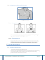
1
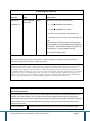
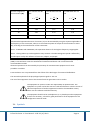
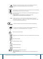
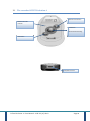
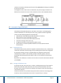
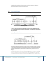
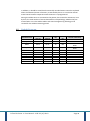
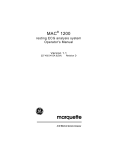
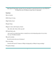
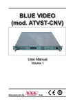
R.TEST Evolution 4 User Manual R.TEST Evolution 4 User Manual NOVACOR SAS 4 passage Saint-Antoine 92508 Rueil-Malmaison Cedex - France R.TEST Evolution 4 Manual NOVACOR SAS - All rights reserved R.Test Evolution 4 - User Manual – 6UK -23/07/2012 Page 2 R.Test4 Evolution 1 CONTENTS ............................................................................................................................................... 5 2 INTRODUCTION ....................................................................................................................................... 7 3 DESCRIPTION OF THE HARDWARE ......................................................................................................... 15 4 OPERATION............................................................................................................................................ 19 5 CONNECTING THE PATIENT .................................................................................................................... 27 6 MAINTENANCE ...................................................................................................................................... 37 7 SPECIFICATIONS ..................................................................................................................................... 39 8 ACCESSORIES AND CONSUMABLES ........................................................................................................ 41 1 Contents 1 CONTENTS ............................................................................................................................................... 5 2 INTRODUCTION........................................................................................................................................ 7 2.1 DESCRIPTION OF THE DEVICE ......................................................................................................................... 7 2.2 THE MANUAL ............................................................................................................................................. 7 2.3 SAFETY INFORMATION ................................................................................................................................. 7 2.4 SYMBOLS ................................................................................................................................................ 11 2.5 GUARANTEES ........................................................................................................................................... 14 2.5.1 Specific Guarantees of the device .................................................................................................... 14 2.5.2 Specific Guarantees of the accessories ............................................................................................ 14 2.5.3 Limits of guarantee ......................................................................................................................... 14 2.5.4 Responsibilities ................................................................................................................................ 14 2.5.1 Users information ............................................................................................................................ 14 2.5.2 Copyrights ....................................................................................................................................... 14 3 DESCRIPTION OF THE HARDWARE ......................................................................................................... 15 3.1 3.2 3.3 4 THE RECORDER R.TEST EVOLUTION 4 .......................................................................................................... 16 R.TEST-PC USB CABLE ............................................................................................................................. 17 ACCESSORIES ........................................................................................................................................... 17 OPERATION............................................................................................................................................ 19 4.1 COLLECTION OF ECG SIGNAL....................................................................................................................... 19 4.2 RECORDING MODES .................................................................................................................................. 20 4.2.1 Manual Recording ........................................................................................................................... 20 4.2.2 Automatic Recording (with the option of patient activated recordings) ......................................... 20 4.3 OPERATION IN MANUAL RECORDING MODE.................................................................................................... 20 4.4 OPERATION IN AUTOMATIC RECORDING MODE ............................................................................................... 20 4.5 AUTOMATIC SIGNAL ANALYSIS .................................................................................................................... 21 4.5.1 Basal heart rate ............................................................................................................................... 21 4.5.2 Storage of the heart rate ................................................................................................................. 21 4.5.3 Detection of rhythm disorders ......................................................................................................... 22 4.6 CONSECUTIVE EVENTS ............................................................................................................................... 24 4.6.1 Simple Events................................................................................................................................... 24 4.6.2 Superimposed Events ...................................................................................................................... 24 4.6.3 Multiple Events ................................................................................................................................ 25 4.7 SETTING OF THE EVENTS IN MEMORY ............................................................................................................ 25 4.8 DEFAULT PROGRAM .................................................................................................................................. 26 5 CONNECTING THE PATIENT .................................................................................................................... 27 5.1 ORDER OF CONNECTION ............................................................................................................................. 28 5.2 CHOICE OF LEAD ....................................................................................................................................... 28 5.2.1 “Neck-Sternum” Configuration ........................................................................................................ 28 5.2.2 Configuration CM5 .......................................................................................................................... 28 R.Test Evolution 4 - User Manual – 6UK -23/07/2012 Page 5 5.3 INSERTING NEW BATTERIES ......................................................................................................................... 28 5.4 PROGRAMMING OF THE RECORDER .............................................................................................................. 29 5.5 CONNECTING THE PATIENT CABLE TO THE R.TEST ........................................................................................... 29 5.6 PLACING THE ELECTRODES AND CONNECTING THE R.TEST ................................................................................. 30 5.6.1 Preparation...................................................................................................................................... 30 5.6.2 “Neck-Sternum” configuration with solid gel electrodes ................................................................ 30 5.6.3 Configuration in CM5: pre-gelled electrodes ................................................................................... 32 5.7 START UP AND HOOK-UP TEST ..................................................................................................................... 32 5.7.1 Startup in continuous mode ............................................................................................................ 32 5.7.2 Disconnection Test .......................................................................................................................... 33 5.8 REMOVING THE R.TEST.............................................................................................................................. 33 5.8.1 End of monitoring ............................................................................................................................ 33 5.8.2 Temporary Interruption of the monitoring ...................................................................................... 33 5.8.3 To Unplug the cable from R.Test ..................................................................................................... 33 5.9 CONNECTION TO A COMPUTER .................................................................................................................... 34 5.9.1 Connecting the R.Test PC cable ....................................................................................................... 34 5.9.2 Disconnection of the cable .............................................................................................................. 34 5.10 RESUMING MONITORING............................................................................................................................ 35 5.10.1 Without changing batteries ........................................................................................................ 35 5.10.2 Changing batteries ...................................................................................................................... 35 6 MAINTENANCE ...................................................................................................................................... 37 6.1 6.2 6.3 6.4 6.5 HANDLING AND USE .................................................................................................................................. 37 CLEANING ............................................................................................................................................... 37 AFTER-SALES SERVICE ................................................................................................................................ 37 STORAGE AND DISPATCHING ....................................................................................................................... 38 PREVENTIVE MAINTENANCE ....................................................................................................................... 38 7 SPECIFICATIONS ..................................................................................................................................... 39 8 ACCESSORIES AND CONSUMABLES ........................................................................................................ 41 R.Test Evolution 4 - User Manual – 6UK -23/07/2012 Page 6 2 Introduction 2.1 Description of the device The R.Test Evolution 4 is a miniature automatic ECG arrhythmia detection device; it is quick and easy to fit to the patient. It is designed to detect and store the most important pathologic events (symptomatic or asymptomatic) as well as the patient’s continuous heart rate, and is capable of up to 32 days of ambulatory monitoring. The system consists of a unit weighing approximately 40 grams that can be worn by the patient unobtrusively and without any discomfort. The R.Test Evolution 4 is connected to the patient by a system of electrodes and a neck cable. Events stored by the R.Test Evolution 4 are then transferred for interpretation via a USB cable connected to a computer. The use of a computer will allow: - the programming of the conditions and criteria for each recording made by the R.Test Evolution 4. - in addition, to select, organize and store the results of the examinations, then to print them in the form of a customised report according to your needs. 2.2 The manual This manual describes the physical operation, instructions, characteristics, technical specifications and the particular recommendations of use of the R.Test Evolution 4 and its accessories. Although the greatest care was taken in its drafting, in order to make it as complete as possible, NOVACOR does not accept any responsibility for any errors, omissions or inaccuracies which it may contain. The functionalities of the device and the accessories, as well as the contents of the manual, can be modified by NOVACOR without notice. 2.3 Safety information Intended Users: The R.Test Evolution 4 is intended for use by a licensed physician or a person working under his supervision. The patient is required to wear the device and should trigger recordings manually, the physician should ensure that the mental and physical condition of the patient is compatible with an R.Test procedure. The physician should inform the patient of the nature of the test and any actions that are required (e.g. removal of the recorder for a shower, manual activation of recordings etc.). R.Test Evolution 4 - User Manual – 6UK -23/07/2012 Page 7 The R.Test 4 should not be used on patients with potentially life-threatening arrhythmias who require inpatient monitoring or on patients who the attending physician thinks should be hospitalised. Recommendations and Manufacturer’s declaration The R.TEST Evolution 4 is meant to be used in an electromagnetic environment only as specified below. The clinician should make sure the device is used in such an environment Electromagnetic Emissions Tests of emissions Conformity Warning prone to the electromagnetic environment Emissions RF Group 1 R.TEST EVOLUTION 4 uses RF energy only for its internal functions. Consequently, its RF emissions are very weak and are not likely to cause interferences in a nearby electronic device. Class B R.TEST EVOLUTION can be used in all institutions, including domestic buildings. CISPR 11 Emissions RF CISPR 11 Emission of harmonics Nonapplicable CIS 61000-3-2 Emission of fluctuation of tension Nonapplicable CIS 61000-3-3 Electromagnetic Immunity Tests of immunity Level of tests CIS 60601 Conformity Warning regarding the electromagnetic environment Electrostatic Discharge + 6kV with the contact Conform If the ground is covered with synthetic materials, it is appropriate that the relative humidity is at least 30%. Conform It is appropriate that the magnetic fields at the frequency of the electrical communication have the levels characteristic of a representative place located in a typical hospital environment. + 8kV in the air Magnetic Fields 3 A/m at the frequency of the electrical communication R.Test Evolution 4 - User Manual – 6UK -23/07/2012 Page 8 Electromagnetic Immunity Tests of immunity Level of tests CIS 60601 Conformity Warning regarding the electromagnetic environment Led RF 3 Veff 3V CIS 61000-4-6 from 150 Khz with 80 MHZ outside tapes ISM It is appropriate that the portable RF devices and mobile communications devices are too not close to every part of R.TEST 4, including the cables; It is advisable to respect the distance from separation recommended, computed starting from the equation applicable to the frequency of the transmitter. (50/60 Hertz) CIS 61000-4-8 Recommended separation distance √ d= recommended separation distance in m p = maximum output power of the transmitter in W Ex: to see table Ci afterwards Interferences can occur near the marked devices of the following symbol: R.Test Evolution 4 - User Manual – 6UK -23/07/2012 Page 9 Electromagnetic Immunity Tests of immunity Level of tests CIS 60601 Conformity Warning regarding the electromagnetic environment Radiated RF 3 V/m of 80MHz with 2,5GHz 3 V/m Outdistance separation recommended CIS 61000-4-3 √ of 80MHz with 800 Mhzs * √ of 800Mhz with 2,5Ghz ** d= distance from separation recommended in m p = maximum power of output of the transmitter out of W Field intensity of RF transmitters should be set, determined by an electromagnetic investigation on locationa, and should be lower than the level of conformity, in each frequency rangeb *Ex : See the following table Note 1: With 80MHz and 800 MHZ, the highest band frequency applies. Note 2: These guides may not apply in all situations. The electromagnetic propagation may be affected by the absorption and reflections of structures, objects and people. a Field intensities of the transmitters that are set, such as base stations for radiotelephones (cellular/wireless) and land mobile radios, amateur radio, radio broadcasting AM and FM, and TV broadcasting, cannot be theoretically forecasted with accuracy. In order to evaluate the electromagnetic environment due to set RF transmitters, an electromagnetic investigation on location must be considered. If the field intensity, measured at the location where the R.TEST Evolution, including the cables, is used, exceeds the level of RF conformity applicable above, the R.TEST Evolution must be observed, including the cables, to check if it is running normally. If abnormal performances are observed, extra measures may be necessary, in order to reorient or reposition the R.TEST Evolution, including the cablesb , on the range of frequencies 150kHz to 80MHz, field intensities must be lower than 3 V/m Separation distances recommended between portable RF devices and/or mobile telephones and R.TEST Evolution 4 R.TEST Evolution 4 is meant to be used in an electromagnetic environment in which RF disturbances are checked. The R.TEST Evolution user can help prevent electromagnetic disturbances by maintaining a minimum distance between the portable device and the RF communication mobile (transmitters) and the R.TEST Evolution, as it is recommended below, according to the maximum transmission power of the communication device. Power of maximum Outdistance separation according to the frequency of the transmitter (m) R.Test Evolution 4 - User Manual – 6UK -23/07/2012 Page 10 emission assigned of the transmitter (W) From 150 Khz with 80 MHZ From 80 MHZ with 800 MHZ √ From 800 MHZ with 2.5 GHZ √ √ 0.01 0.12 0.12 0.23 0.1 0.37 0.37 0.74 1 1.17 1.17 2.33 10 3.70 3.70 7.37 100 11.70 11.70 23.30 For transmitters for which the maximum transmission power assigned is not displayed above, the recommended separation distance d in meters (m) can be estimated by using the equation applicable to the frequency of the transmitter, where P is the maximum power of output of the transmitter in watts (W), according to the manufacturer of that transmitter. Note 1 : At 80 MHz and at 800 MHz, The separation distance for the highest frequency range applies. Note 2 : These guides may not be applied in every situation. The electromagnetic spread is affected by the absorption and by the reflexion of structures, objects, and people Precautions for use must be taken with respect to the phenomena of electromagnetic compatibility (CEM). R.Test Evolution 4 must be installed and commissioned above and in accordance with recommendations CEM. Abnormal operations can be caused by the proximity of communication equipment such as RF portables or mobiles. R.Test Evolution 4 is not protected from the effects of the discharges of an external defibrillator. The minimal amplitude of the physiological patient signals is: 0.5 mV The use of the equipment close to this minimal level can generate incorrect results. The equipment or system is under the responsibility of qualified staff. This equipment or system can be the source of radio interferences or be the source of abnormal operations of another apparatus located in the immediate vicinity. Some care of instalment could be necessary. The equipment should not be used adjacent to, or placed upon other equipment. If this use is necessary, a check for good performance of the equipment in this configuration must be made. 2.4 Symbols R.Test Evolution 4 - User Manual – 6UK -23/07/2012 Page 11 This sign on an apparatus indicates to the user that additional information, available in the accompanying documents, must be consulted. R.Test Evolution 4 works exclusively with an internal power source and complies with standards of protection for units in class BF. IPX4 CEM Fitted with its ECG cable, R.Test Evolution 4 is classified IPx4 (protected against water projections) R.TEST Evolution 4 is not an apparatus of category AP nor APG R.TEST Evolution 4 is planned for a continuous service. R.TEST Evolution 4 is in conformity with the Electromagnetic standard of Compatibility EN 60 601-1-2. However, if it is used in a very specific way, there can be some problems with interference CE Mark, according to European Directive 93/42/CEE for medical devices The device does not possess any specific protection against humidity, as a consequence, it is recommended to store it in a dry place. Risk associated with the ESDs The product must be eliminated in a structure of suitable recovery and recycling Store away from light Storage Temperature Limits Humidity Storage Limits Pressure Storage Limits Connecting the ECG cable to the patient : When connecting it: Always connect the cable to the recorder first, then to the electrodes on the patient. R.Test Evolution 4 - User Manual – 6UK -23/07/2012 Page 12 When removing the unit: Always disconnect the ECG cable from the electrodes on the patient before unplugging the cable from the recorder. NOVACOR will provide electrical circuit diagrams and information about the nature of the materials for customers if required. R.Test Evolution 4 - User Manual – 6UK -23/07/2012 Page 13 2.5 Guarantees NOVACOR undertakes to deliver merchandise conforming to the technical specifications mentioned and to replace any merchandise recognised as being defective during the period of guarantee. 2.5.1 Specific Guarantees of the device NOVACOR guarantees the unit for the period of one year from the date of delivery against any defect resulting in the unit functioning abnormally. 2.5.2 Specific Guarantees of the accessories The parts or components not considered an integral part of the device, and in particular the accessories and cables, do not benefit from any particular guarantee. 2.5.3 Limits of guarantee The guarantee does not apply: 1. if the device is repaired or opened outside of our workshops. 2. if the device is damaged following negligence, accident, or use that does not conform with the procedures described in the instruction manual. If necessary, please contact your local distributor or our after-sales service directly. We do not accept any return of goods without prior arrangement. 2.5.4 Responsibilities NOVACOR will not, under any circumstances, be held responsible for physical or material damage of whatever nature, resulting either directly or indirectly from improper use of the unit or from failure to follow the instructions in the user manual. Although NOVACOR manufactures products to the highest standards, justifying customer confidence, it cannot guarantee or be responsible for the validity or accuracy of the measurements made with its units. Therefore, connection of the unit to the patient, interpretation of the ensuing clinical results and the diagnosis established from them are the entire responsibility of the physician. No damage, either direct or indirect, resulting from the use of one of its units can be attributed to NOVACOR, excluding the repair of the unit within the limits of the guarantee. 2.5.1 Users information All the customers duly recorded at NOVACOR or if necessary by its distributors, will be kept informed as well as possible of various developments of R.TEST Evolution 4. 2.5.2 Copyrights Manual R.TEST Evolution 4 ©2011 Novacor SAS - All rights reserved. R.Test is a registered trademark of NOVACOR SAS. Windows is a registered trademark of Microsoft Corporation. R.Test Evolution 4 - User Manual – 6UK -23/07/2012 Page 14 3 Description of the hardware R.TEST Evolution 4 is a recorder / analyser of ECG events ambulatory, automatic or manual, single channel, long term, Intended for asymptomatic and/or symptomatic patients. R.Test Evolution 4 - User Manual – 6UK -23/07/2012 Page 15 3.1 The recorder R.TEST Evolution 4 Real time transmission Multifunction LED Indicator Initialisation + Manual Event Recording Information ECG/USB Connector R.Test Evolution 4 - User Manual – 6UK -23/07/2012 Page 16 3.2 R.Test-PC USB Cable 3.3 Accessories 1- neck cable 2 – Pre-gelled electrodes. 3 - Reinforcements of electrodes. 4 - Metal electrodes. CM5Cable (standard 40 cm or long 57 cm) R.Test Evolution 4 - User Manual – 6UK -23/07/2012 Page 17 The use of accessories, sensors and cables other than those specified can induce an increase in the levels of emission or a reduction in the levels of immunity of the equipment. R.Test Evolution 4 - User Manual – 6UK -23/07/2012 Page 18 4 Operation 4.1 Collection of ECG signal The surface ECG signal is collected according to a bipolar configuration between two ECG electrodes especially adapted to the R.Test. The apparatus is integrated directly with one of the electrodes, in contact with the patient’s sternum. The second electrode, placed either behind the neck or on the patient’s side, is connected to the R.Test by using the supplied accessory. The physician is free to choose between the “neck-sternum” and the “CM5 lead” configurations, there is a specially designed cable for each. The neck-sternum configuration allows the collection of the ECG signal characterised by: a morphology and an amplitude of QRS similar to V2, significantly different right and left ventricular activations, generally optimal P waves amplitude. The CM5 configuration allows collection of the ECG signal characterised by: a morphology and an amplitude of QRS similar to V5, an amplitude often greater than the ‘neck-sternum’ configuration The CM5 cable may provide a better recording of ST changes and give more flexibility when the anatomy of the patient’s sternum makes it impossible to connect the R.Test normally. The R.Test stores significant ECG events in its memory. The physician can pre-program the duration of these events and the mode in which they will be recorded: - automatically (for asymptomatic problems), according to recognition criteria specific to each pathology, - or by patient activation (pressing the recording key) (for symptomatic events, whether they be cardiac or not). R.Test Evolution 4 - User Manual – 6UK -23/07/2012 Page 19 4.2 Recording modes The clinician can decide to use one of the two options below: 4.2.1 Manual Recording The ECG is recorded by the R.Test, for one predetermined length of time, without analysis or processing, when the patient presses on the manual event button on the device. Each recording is obtained according to the pre and post event durations set in the current program, configurable by the clinician, via the software. 4.2.2 Automatic Recording (with the option of patient activated recordings) The ECG signal is processed and analysed in real time, and the most significant pathologies are stored into the memory of the device. Each recording is obtained according to the criteria and to the pre and post event durations set in the current program, configurable by the clinician, via the software. 4.3 Operation in manual recording mode This mode is intended for symptomatic patients, for whom one wishes to carry out a recording of the crisis or symptom, even if this symptom is not very frequent. The patient simply has to press the R.Test recording key and the ECG recording will then be saved in the unit’s memory. This recording is stored, without being analysed or interpreted, so that the physician can examine it later on. 4.4 Operation in automatic recording mode The R.Test monitors the ECG signal continuously and stores it in a loop memory, which therefore contains, at any given moment, the previous few minutes of the ECG recording; this means that a given duration of the ECG preceding a detected event can be included in the recording. This duration, called the pre-event, can vary from 5 seconds to 5 minutes. During the detection of an event, R.TEST Evolution 4 will record the ECG corresponding to the pre-event recording time defined for this type of event and will R.Test Evolution 4 - User Manual – 6UK -23/07/2012 Page 20 continue to memorise the ECG until the end of the post-event recording time defined for this type of event. If during post-event, other events are detected, they will be simply marked on the ECG but the R.Test will not start a new recording (see also § 4.6.3 Multiple Events). 4.5 Automatic Signal Analysis The analysis of the ECG takes place in real time in the R.Test: as the ECG signal is stored in the buffer, the microchip of R.Test, using a specific software algorithm, carries out the following operations automatically: identification of the QRS and possible elimination of artefacts, determination of the morphology of the QRS, calculation of R-R intervals and the basal heart rate, continuous storage of the heart rate, recognition and hourly counting of arrhythmic events, memorisation of selected episodes with date and time, QRS and events characteristics 4.5.1 Basal heart rate The reference R-R interval, which corresponds to the basal heart rate, is obtained by continuous calculation of the average of the preceding few R-R intervals recognised by the R.Test as being “normal”. Excluded from this average are R-R intervals considered not “normal”, these include: periods of artefact, pauses, intervals preceding and following premature QRS (in order to also eliminate compensatory pauses). By default this calculation is carried out on the last 8 “normal” R-R intervals collected (noted RR8N). 4.5.2 Storage of the heart rate At regular intervals, the R.Test stores 3 values, enabling assessment of the patient’s heart rate trend to be made: minimum rate, mean rate and maximum rate. The duration of this interval is chosen according to the length of time that the patient is connected to the unit. The R.Test therefore also provides the physician with continuous monitoring of the minimum, mean and maximum heart rates for a period of up to 32 days. R.Test Evolution 4 - User Manual – 6UK -23/07/2012 Page 21 Duration of examination Sampling of the HR 4.5.3 < 48h From 2 to 4 days From 4 to 8 days From 8 to 16 days From 16 to 32 days 1' 2' 4' 8' 16' Detection of rhythm disorders Arrhythmias detected by the R.Test are classified in several categories. Some automatic functions of the R.Test Evolution 4 may be available only as additional options. 4.5.3.1 Fast Rhythm disorders (premature QRS and salvos) A QRS is considered as premature if the R-R interval preceding it is lower by a given percentage (standard program 25%) compared to the base period (RR8N). The R.Test characterises premature QRS according to: - The morphology: Normal or Narrow QRS as “Supraventricular” Aberrant or Wide QRS as “Ventricular” - Their organisation: Isolated QRS, Couplets and Triplets (1, 2 or 3 consecutive premature QRS) Runs (4 or more consecutive premature QRS). This identification enables the R.Test to distinguish 8 subcategories of rapid events: Isolated Supraventricular Ectopic Supraventricular Couplets Supraventricular Triplets Supraventricular Runs Isolated Ventricular Ectopic Ventricular Couplets Ventricular Triplets Ventricular Runs In the case of the isolated events, couplets and triplets of the same type, the reserved memory capacity is common. If the memory is full, a new event will replace another according to the following criteria of gravity: a triplet is more serious than a couplet, which itself is more serious than an isolated premature QRS. Standard program: RR < RR8N - 25% * RR8N 4.5.3.2 Absolute Pauses Characterised by an R-R interval exceeding a certain duration, whatever the morphology of the QRS, and irrespective of the presence of a premature QRS. Standard program: RR > 2.0 seconds R.Test Evolution 4 - User Manual – 6UK -23/07/2012 Page 22 4.5.3.3 Relative Pauses Characterised by an R-R interval exceeding a given percentage of the mean reference R-R interval, providing that it does not follow a premature QRS complex, and that its duration is shorter than the absolute pause threshold. Standard program: RR > 175% * RR8N 4.5.3.4 Bradycardia Characterised by the decrease of the reference heart rate below a threshold, with a minimum of 8 consecutive RR intervals. Standard program: 8xRR < 40 BPM 4.5.3.5 Sinus Tachycardia Characterised by the increase of the reference heart rate above a given threshold Standard program: 8xRR > 140 BPM 4.5.3.6 ST Segment Analysis The ST segment is characterised by its shift compared to the base line: it can be positive (elevation), or negative (depression). It is measured in millimetres (mm), the scale of the ordinates being of 1 mV/cm. Location of the measurement points An ST episode can be recorded by the R.Test if, during 32 QRS, the shift is larger than the programmed threshold. For the histograms, the R.Test computes the averages shift for each 30’’period, and retains the maximum and minimum shift values. 4.5.3.7 Atrial Fibrillation Analysis Atrial fibrillation is often associated with a fast and irregular heart rate. An analysis of the rhythm makes it possible to detect episodes of AF. The algorithm used analyses R.Test Evolution 4 - User Manual – 6UK -23/07/2012 Page 23 the width of the distribution of R-R intervals as well as the temporal stability of alternations between regular and irregular states. 4.6 Consecutive Events 4.6.1 Simple Events Simple Events In general, two consecutive events detected by the R.Test are sufficiently far apart from one another for their recordings to be separate. These two events are therefore two single events. 4.6.2 Superimposed Events Superimposed Events If the interval separating two events is lower than the post-event duration of the first + pre-event of the second, and the second event actually occurs after the post event of the first has finished, they will each be recorded normally, each one in its own category. Contrary to the operation of R.Tests of preceding generations, the second recording will not be shifted in time: the concept of chain events no longer exists with R.Test Evolution 4. Each event respects its parameter settings of pre-event and post-event. R.Test Evolution 4 - User Manual – 6UK -23/07/2012 Page 24 4.6.3 Multiple Events Multiple Events When two consecutive events are such that the second occurs in the post-event of the first, the second will not be recorded separately. However, if it is either an absolute pause, or a run (i.e. at least 4 consecutive premature QRS), the recording of this double event will be identified as a “multiple event”. 4.7 Setting of the events in memory When the R.Test is programmed, the total duration of its memory is divided up between the different types of pathologies. The number of events of each type which can be memorised by the R.Test depends on: - the size of the memory allocated to that type of event and - the duration of the recording period chosen for each episode (pre-event + postevent). In addition to this, each time an event corresponding to one of the pre-defined pathologies is identified: - the event counter for this type of pathology is incremented by 1 in the corresponding hour segment, and - the severity of the event is measured; for pauses, according to their duration; for premature complexes, according to their number; and for Bradycardia/Tachycardia and runs, according to their rate. The R.Test stores only the most serious detected events: When the memory allocated for a given “type” of pathology is saturated, the R.Test does not memorise a new event of the same type unless it more serious than the least serious event it has already preserved. In the case that a new event is more serious, in order to free enough memory for this new event, the least serious event is erased. This rule does not apply to the multiple events, which, once memorised, cannot be overridden. R.Test Evolution 4 - User Manual – 6UK -23/07/2012 Page 25 In addition, it should be noted that the manually recorded events cannot be replaced when the allocated portion of memory is saturated by them: as a result the manual event button becomes inoperative until the R.Test is reprogrammed. During the whole time it is connected to the patient, the R.Test also memorises, hour by hour, the total number of events detected for each pathology, whether they are memorised or not. This enables tables and event histograms by pathology to be created for the whole monitoring period. 4.8 Default Program VT VEs (1 to 3) Pre-event (mm:ss) 00:15 00:15 Post-event (mm:ss) 00:15 00:15 PSVT 00:15 SVEs (1 to 3) Absolute Pauses Relative Pauses Tachycardia Bradycardia ST shifts AF Manual Markers Standard event 10 21 Duration (S) 300 630 00:15 10 300 00:15 00:15 21 630 00:15 00:15 00:15 00:15 00:25 00:15 00:20 00:15 00:15 00:15 00:15 00:15 00:30 00:10 10 4 8 8 6 8 8 300 120 240 240 240 360 240 R.Test Evolution 4 - User Manual – 6UK -23/07/2012 Qty Criteria of detection Threshold < RR8N - 25% RR8N Threshold < RR8N - 25% RR8N RR > 2.0 S RR > 175% RR8N Threshold > 140 bpm Threshold < 40 bpm Offset ≥ 2 mm Page 26 5 Connecting the patient The R.Test Evolution is usually connected to the patient, using ECG electrodes, with the CM5 lead, although another lead (such as the “NeckSternum”) can be preferred. If the physician only wants to obtain manual recordings with no pre-event duration, the unit can be worn “loose” around the patient’s neck. In this case, the patient holds the R.Test Evolution, through his clothes, against his skin during the recording. The “Neck-Sternum” lead and metal electrodes can be used. The patient is connected as described below for most cases (ECG electrodes) R.Test Evolution 4 - User Manual – 6UK -23/07/2012 Page 27 5.1 Order of connection - Choice of lead - Inserting new batteries - Initialising the unit - Connecting the patient cable to the R.Test - Placing the electrodes on the patient and connecting the R.Test - Start up and start up test 5.2 Choice of lead 5.2.1 “Neck-Sternum” Configuration This configuration, which gives an ECG signal of very good quality, in particular with clear P waves, requires the use of the `neck cable’ (ref. ACC-0105-00). It must also be chosen to carry out specific “manual only” recordings, with metal electrodes, on symptomatic patients. 5.2.2 Configuration CM5 In some cases the “Neck-Sternum” lead will not be chosen, particularly if the QRS amplitude is inadequate. A preliminary decision can be made by examining the surface ECG: If the peak-to-peak amplitude of the QRS in V2 is less than 1 mV, it is best not to use the Neck-Sternum lead, and to choose, for example, the CM5 lead instead. The CM5 lead may also be used for analysis of ST segment changes, or if there are problems with the patient’s sternum. CM5 is the standard lead supplied with the R.Test Evolution 4. 5.3 Inserting new batteries The replacement of the used batteries should be carried out just before the initialisation of the R.Test in order that it can function for the longest possible time. The use of special NOVACOR batteries allows the operation of the R.Test for up to 16 days in automatic mode with all options activated. The R.Test should be used only with Zinc-Air 1.4V batteries PR44 respecting the polarity of insertion. Do not forget to remove the cover placed on the bottom of the batteries before use. R.Test Evolution 4 - User Manual – 6UK -23/07/2012 Page 28 - Insert the new batteries by respecting the polarity indicated, the + side (bottom of the batteries) directed upwards. The R.Test then begins a cycle of battery checks for a few seconds ending with a double tone. If the batteries are new, the LED illuminates green for 5 seconds If the batteries are not new, the LED illuminates orange for 5 seconds If the batteries are low, the LED illuminates in red for 5 seconds 5.4 Programming of the recorder Connect the R.TEST Evolution 4 to the PC via the USB cable, then Program/Read via the software to choose the program to be used as well as to input patient information. Note: it is not necessary to have inserted batteries to read or program and R.TEST Evolution 4 with the USB cable. 5.5 Connecting the Patient Cable to the R.Test R.Test /cable R.Test Evolution 4 - User Manual – 6UK -23/07/2012 Page 29 Make sure that the connector is lined up with the R.Test so that the logos on the connector and the front plate of the R.Test are visible at the same time. Guide the connector into the unit until it is locked into position. 5.6 Placing the electrodes and connecting the R.Test 5.6.1 Preparation Novacor recommends the exclusive use of the specially selected electrodes for R.Test monitoring, which are supplied in sealed pouches. These electrodes are hypoallergenic (Ag-AgCl) and can normally be worn for several days without any side effects. However, people with sensitive skin may have an allergic reaction (rashes, spots, etc.). These reactions will usually disappear spontaneously a few days after the electrodes are removed. If the patient’s skin is particularly sensitive, wait until the rash has completely disappeared before placing electrodes on him again, and take any other precautions that you consider necessary. The installation of the electrodes for the R.Test requires careful preparation of the patients’ skin: it is recommended to shave the site of the electrodes where necessary, and if clean the area with a suitable wipe and then thoroughly dry. 5.6.2 “Neck-Sternum” configuration with solid gel electrodes Neck-Sternum configuration R.Test Evolution 4 - User Manual – 6UK -23/07/2012 Page 30 5.6.2.1 Connecting the sternal electrode Sternal electrode Electrode with reinforcement Place the sternal electrode first, on the lower third of the sternum, if possible, or, in any case, as low as possible (if the patient’s chest is particularly large). Adhesive patches must be used to make sure that the solid gel electrodes adhere properly, especially for patients who perspire heavily or who will be connected to the R.Test for more than 24 hours. 5.6.2.2 Connecting the cervical electrode Cervical Electrode Electrode plus adhesive patch Put the R.Test and cable around the patients neck like a necklace, without attaching the unit to the sternum, and let it hang naturally against the cervico-thoracic spine. Locate the place where the neck electrode will be applied (round electrode), put it in place, then stick the adhesive patch over it (popper through a hole). Then connect the neck electrode, followed by the sternal electrode to the R.Test by simply applying light pressure. R.Test Evolution 4 - User Manual – 6UK -23/07/2012 Page 31 5.6.3 Configuration in CM5: pre-gelled electrodes Configuration in CM5 5.6.3.1 Placing the electrodes Sternal and V5 electrodes plus adhesive patch This is connected in the same way except that the sternal electrode is placed higher up, on the sternal manubrium, ideally at the angle of Louis. Then place the electrode in V5 as indicated. 5.6.3.2 Connecting the R.Test Plug the CM5 cable into the R.Test as indicated before for the neck-sternum cable, put the spiral support part around the patients neck, then click the R.Test onto the sternal electrode and the distant connector to the electrode in the V5 position. 5.7 Start up and hook-up test 5.7.1 Startup in continuous mode - Press on the central key on the device to start. The R.Test emits a signal modulated by the ECG. The modulation of the signal, during its 20 seconds duration, makes it possible to immediately detect with the ear, possible anomalies in the detection of the ECG. R.Test Evolution 4 - User Manual – 6UK -23/07/2012 Page 32 - After these 20 seconds, the recording starts and R.Test emits a beep synchronised with each detected QRS. In the absence of visualisation of the signal a perfect synchronization of the beeps with the pulse of the patient during at least 30 seconds constitutes the best guarantee that the selected configuration is sufficient in amplitude (>1 mV). In automatic mode, this check is imperative if you want to ensure a reliable detection. If it proves to be negative, it is advisable to check the quality of the connections and the positioning of the electrodes. - Once you are happy, press again on the central key to stop the beeps and to allow manual recordings to be made. Throughout the entire recording, the Led emits a green flash every 5 seconds to indicate the status is ‘recording in progress’. 5.7.2 Disconnection Test If the disconnection alarm has been programmed (recommended), disconnect the unit or the cable from an electrode for a few seconds to activate it and explain what it means to the patient. The warning signal will be emitted every 15 minutes by the R.Test until the problem has been resolved, for example by replacing an electrode which has come unstuck or has dried out. (The patient should be provided with an extra set of electrodes in case he needs them). 5.8 Removing the R.Test 5.8.1 End of monitoring If the R.Test monitoring is not to continue after data transfer, simply disconnect the recorder together with its cable from the electrodes. The electrodes can then be removed and the patient’s skin can then be cleaned and dried, if required, following any instructions given by the physician. 5.8.2 Temporary Interruption of the monitoring You can choose: - to proceed as previously described , and after the data transfer to replace the electrodes with new ones, or - to leave the electrodes in place: disconnect the R.Test from its sternal electrode, and then unplug the cable from the R.Test as described below. 5.8.3 To Unplug the cable from R.Test This operation must be carried out very carefully, so as not to damage the unit nor the cable. Training beforehand is essential: R.Test Evolution 4 - User Manual – 6UK -23/07/2012 Page 33 To disconnect the cable from the unit, the connector must first be unlocked: do not pull using brute force, the unit could be damaged! Press firmly on the two faces of the connector (marked PRESS), and pull straight until clear, as indicated in the picture above. 5.9 Connection to a computer 5.9.1 Connecting the R.Test PC cable Completely engage the R.Test on the connector, in accordance with the symbol shown on the interior of the connector, until the two red positioning triangles are exactly face-to-face: Correctly connected R.Test and connector 5.9.2 Disconnection of the cable To disconnect R.Test from the cable: After having turned over the R.Test-connector, it is necessary to: R.Test Evolution 4 - User Manual – 6UK -23/07/2012 Page 34 press firmly on the serrated part of the connector, using the thumb and forefinger, before releasing the R.Test from the connector by moving them apart. 5.10 Resuming monitoring 5.10.1 Without changing batteries It is possible, after reading the R.Test data, to continue the recording for the same patient. Simply reconnect the R.Test and its cable to the patient electrodes, the procedure continues automatically. 5.10.2 Changing batteries Carry Out the change of the batteries as indicated in the §5.3 Inserting new batteries. After the start up, the led must flicker green once every five seconds. Then simply reconnect the R.Test and its cable to the patient electrodes, the procedures continues automatically. R.Test Evolution 4 - User Manual – 6UK -23/07/2012 Page 35 6 Maintenance 6.1 Handling and use The installation of the apparatus to a patient must be carried out by a qualified person. Always press the centre of the recorder’s keys; never use a blunt or pointed object or your finger nail. The R.Test Evolution 4 can be fitted to children of less than ten kilograms. If you believe there is any risk of strangulation with the spiral cord of the CM5 cable, you can decide not to place it around the neck or alternatively make use of the V5 cable. Operation in moist environment: The R.TEST Evolution 4 is water resistant to IPx4 and is protected from splashing water projections. However, the device does not have any specific protection against moisture when the ECG cable is not connected. Do not use the R.TEST 4 if any part, including the cables, appears broken or damaged. Do not make any additions or modifications to the equipment, other than fitting a replacement Novacor branded cable, but return it to your dealer for repair. 6.2 Cleaning Before carrying out cleaning, the cable must be connected and the batteries removed. Regularly clean and disinfect the R.Test Evolution 4 and its accessories. We recommend gently wiping with surgical spirit (70%), never use very strong disinfectants such as nail polish remover or acetone. Never leave the device in touch with liquid or a wet tissue If you want to use another cleaning product, make a preliminary test to ensure there is no degradation to the coating. In particular, it is recommended to thoroughly clean the ECG cables between patients. 6.3 After-sales Service Maintenance is carried out in our workshop, as rapidly as possible. We are unable, however, to provide a unit on loan during the repair period or to provide compensation of any sort. R.Test Evolution 4 - User Manual – 6UK -23/07/2012 Page 37 In all cases, including units under guarantee, transport costs are the customer’s responsibility. If the unit is examined outside the guarantee period, there will be a minimum charge for administrative and testing costs. An estimate will be sent by mail or fax upon receipt of the unit and completion of the diagnostic tests. No repair can take place without a signed order from the customer. 6.4 Storage and dispatching Take care to remove the R.Test Evolution 4 batteries if the device will be stored for more than a few days. During shipping, the R.Test Evolution 4 is protected by its packaging. This should be kept in case it is needed at a later date; it also contains a Complaint Report form you will be able to use in the event of incident during the use of the device. When throwing out the batteries use proper containers, following any applicable local laws. You must respect the current regulations concerning the disposal of the unit. 6.5 Preventive Maintenance A preventive check-up of the recorder is recommended every two years. This checkup will reduce the number of potential break downs and prolong its useful life. The unit will be checked for its correct functioning, in particular ECG amplifiers and safeguard battery The check-up must be carried out in our workshop, or by an approved distributor. The invoicing covers the tests only, the quote for any necessary repair will be sent by mail or by fax. The repair can only be carried out upon reception of a customer order. R.Test Evolution 4 - User Manual – 6UK -23/07/2012 Page 38 7 Specifications R.TEST EVOLUTION 4 Evolution Overall Length 60 mm Overall Width 48 mm Overall Depth 28 mm Weight with batteries 40 g. Index IP (with ECG cable in place) IPX4 Conditions of storage/transport Operating Conditions Batteries Type Type of recorder Type of events (automatic mode) Maximum Number of events Duration of the events automatic mode manual mode only R.Test Evolution 4 - User Manual – 6UK -23/07/2012 Temperature - 20 °C to + 45 °C Moisture 10% to 95% (non condensing) Pressure 500hPA to 1060hPA Temperature + 10 °C to + 45 °C Moisture 10% to 99% Pressure 700hPA to 1060hPA 675 Zinc Air IEC - PR44 ANSI/NEDA - 7003ZD Automatic Recorder/ ECG Arrhythmia detection and Heart Rate trend. Manual Recorder of ECG episodes. Supraventricular and Ventricular QRS, (Isolated, couplets, triplets and runs). Absolute and relative Pauses. Bradycardia, Tachycardia ST shifts, Atrial Fibrillation Manual Markers 256 Programmable from 10s to 60 min, with pre-event minimum 5s, maximum 5 min, post-event minimum 5s, maximum 59 min 55s (looping memory). pre-event 0 + post-event 30s to 60min Page 39 Total Duration of recording ECG events Heart rate and histograms trend Maximum Duration of an examination automatic mode manual mode only Electrical Supply Number of channels Data Storage Memory Lifetime Sampling and analysis Vertical Resolution Precision of the ECG in duration Precision of the ECG in voltage: Storage PC connection R.Test Evolution 4 - User Manual – 6UK -23/07/2012 60 min 32 days 32 days 2 months 2 x zinc-air 1.4 V - 640 mAh batteries 1 Non-volatile Stable Memory 10 billion cycles 200 Hz 10bits ± 2.5 ms ± 6 µV 100 Hz USB2.0 Full compatible Speed Page 40 8 Accessories and consumables The following accessories and consumables are available from your supplier: Accessory & Consumables Reference Conditioning Special Batteries Pre-gelled Ag-AgCl Electrodes Neck Cable (configuration neck-sternum) CM5 Cable standard 40 cm CM5 Cable long 60 cm V5 cable standard 30cm V5 cable long 60cm Battery Cover (RT4) R.Test - PC USB Cable Software RTSoft PC User Manual R.TEST Evolution 4 (this handbook) ACC-0706-00 ACC-203-00 ACC-0105-00 ACC-0105-03 ACC-0105-04 ACC-0106-01 ACC-0107-01 ACC-0603-02 ACC-0159-00 LOG-0700-05 Box of 60 batteries Box of 50 electrodes 1 part 1 part 1 part 1 part 1 part 1 part 1 part CD Applications CD Applications R.Test Evolution 4 - User Manual – 6UK -23/07/2012 Page 41 R.Test Evolution 4 - User Manual – 6UK -23/07/2012 Page 42