1
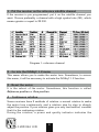
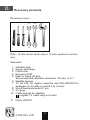
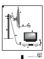
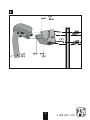
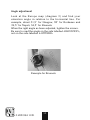
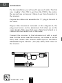
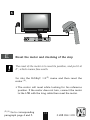
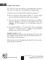
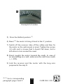
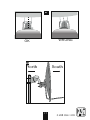
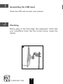
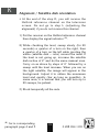
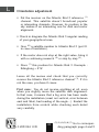
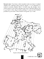
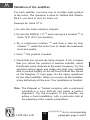
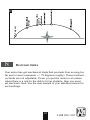
INSTALLATION GUIDE
FOR THE MOTOR
Motor Horizon-Horizon
ref 450907
MET445
0 208 994 1181
2
1
A
Motorised installation
Foreword
This user manual will explain to you how to install a motorised
installation with a motor ref: 450907.
Such installation needs some operations, on the motor, but
also on the satellite receiver you intend to use with.
As the motor can work with all types of receivers, it is
impossible to be precise on the kind of operations that you
will have to do on your receiver. We then advise you to
read both user manual very carefully (this one and the one
from the receiver) to identify what you will have to do on
the remote control. That will allow you to do the necessary
operations for each unit. These are some small advices to
help.
Your motor is compliant with all satellite receivers labelled
DiSEq 1.2. Furthermore, it is also compliant with receivers
featuring the «Goto X» option, witch is also sometimes called
USALSTM. USALSTM is a trademark own by STAB.
3
0 208 994 1181
1 - Put the receiver on the reference satellite channel
If the receiver is pre programmed, put it on the satellite channel you
want. Choose preferably a channel with a high symbol rate (SR), which
means greater or equal to 22 000.
Diagram 1: reference channel
2 - Go into the DiSEqC 1.2 menu
This menu allows you to make the motor turn. Sometimes, to access
this menu, it will be necessary to activate the DiSEqC 1.2 function.
3 - Reset the motor
It is the reboot of the motor. Sometimes, this function is called
Reference position or Zero position.
4 - Continuous rotation
Some receivers have 2 methods of rotation: a normal rotation to make
the motor turn continuously, and a rotation step by step to sharply
adjust the position. If your receiver gives you only one method, consider
that it is the continuing rotation.
During the rotation, a power and quality indicator indicates the
0 208 994 1181
4
reception level.
Note: The size of the level indicator does not have a real importance in
itself. What is important it is the variation when you move the dish
or the motor. When the level is going up a bit, stop the rotation to
check if the quality level increases.
5 - Step by step rotation
If your receiver has the step-by-step rotation, you will be able to adjust
accurately the motor position. If it is not the case, try to reach as precisely as possible the desired angle with a continuing rotation. It is useful to keep the degree order precision.
6 - Give a number to a satellite
Check in your receiver user manual how to associate a number to each
satellite. If it is not possible, leave the existing number system.
7 - Store a satellite position
This function is generally called memorised, store, saved…
8 - Display the signal indicator
Generally, the signal indicator appears when pressing on the INFO key.
Sometimes, you have to access the channel search menu. The indicator
is often showed as two bars. For the alignment, you need to maximise
the signal then, when it is going up, optimise the quality. If the level is
high, but the quality is not going up, that means that you are on another
satellite, you must continue to scan.
The level is always measured on a give channel. So, we will define, for
each satellite, a «reference channel» as the channel used to find this
satellite. The following table lists a set of reference channels. With time,
it is possible that one or more of these channels is no longer broadcast
or has its technical data change. If so, choose any other channel of the
satellite as a reference channel, provided that the Symbol Rate (SR) is
bigger than 22000.
5
0 208 994 1181
B
Necessary elements
Necessary tools:
11
13
10
12
Note : for the motor itself, only a 13 mm spanner is necessary.
Elements:
1
2
3
4
5
6
7
8
9
10
Satellite dish
Screw and fixing
Offset arm
Universal LNB
Mast or stand off arm
Recommended diameter minimum: 40 mm (1,6’’)
Satellite receiver
TV set PAL for digital reception and PAL/SECAM for
analogue (to be able to watch it in colour)
Scart lead male/male 21 pin
«F» plug
Cable special for satellite,
(regular TV cable may not work)
11 Motor 450907
0 208 994 1181
6
1
1
11
2
4
3
5
7
10
8
9
6
7
0 208 994 1181
C
Prepare the motor (see diagram 2)
Assembling
• Make sure the fixing (tube or stand off arm) is stable and
strictly vertical. An error bigger than 1 degree (2 cm, or
3/4 inch per meter) from the vertical will preclude the
motor for working properly. If necessary, add some block
between the wall and the fixing. Check the verticality
with a spirit level or a plumb line.
• Assemble together the parts of the motor (diagram 2).
Put first the U-screws (1) through the part (2). While
assembling the part (2) with the body, pay attention to
the washer (3) : the part labelled «down» must be placed
on the bottom, as shown on the picture.
• Once the motor is assembled, do not fix it straight away
on the mast or the stand off arm, some operations needs
to be done near the receiver first.
0 208 994 1181
8
2
(3)
(2)
(4)
(1)
(3)
9
0 208 994 1181
Angle adjustment
Look at the Europe map (diagram 3) and find your
elevation angle in relation to the horizontal line. For
example, about 31,5° for Glasgow, 38° for Bordeaux and
39,5° for Napoli, 34,5° for Brussels.
When the right angle as been adjusted, tighten the screws.
Be sure to read the angle on the side labelled «ELEVATION»,
not on the side labelled «LATITUDE»
Example for Brussels
0 208 994 1181
10
3
Inclination and angular reading for Hotbird 3
11
0 208 994 1181
D
Connection
For the installation you will need 2 pieces of cable. The first
one, roughly 1,5m (5ft) to go from the LNB to the motor,
the second one as long as it takes to go from the motor to
the receiver.
Prepare the cables and assemble the “F” plug at the end of
the cable.
Respect the dimension indicated on the diagram 4; the
plug must screw on the aluminium foil rolled up on the
outer sheath. Make sure that none of the braid strand is in
contact with the central core of the cable.
Connect the receiver to the television set with a scart
lead. Put the motor near the receiver, on a table or on the
floor, and connect the receiver LNB input to the Motor
RECEIVER output with the 1,5m (5ft) cable, then switch on
the receiver.
4
����
0 208 994 1181
12
����
5
receiver
E
Reset the motor and checking of the stop
The reset of the motor is to reset its position, and put it at
0°, which means face south.
Go into the DiSEqC 1.2 (2) menu and then reset the
motor (3).
• The motor will reset while looking for his reference
position. If the motor does not turn, connect the motor
to the LNB with the long cable then reset the motor.
(2)(3)
Go to corresponding
paragraph page 4 and 5.
13
0 208 994 1181
F
Prepare the motor
You will now store the position of Hot Bird then put back
the motor precisely at 0° to assemble the satellite dish.
1) Put the receiver on the Hotbird reference channel (1).
2) Give a number to the Hotbird satellite (6) (in any doubt
put 4), and then wait that the motor stops turning.
3) Look on the map of Europe (3) and find your Hotbird
angular reading in relation to the vertical lines. For
example, 18° E in Glasgow, 15° E in Bordeaux, and 2°W
in Napoli.
4) Go into the DiSEqC 1.2(2) menu then, with a continuing
rotation (4) , bring the motor roughly on the Hotbird
azimuth with a step by step rotation (5).
Example: London = 14°
With the remote control you must make the motor turn until
the metallic notch used to read the azimuth reaches 14°.
See example on the picture 6.
When the arrow is on the right hand side of the 0, the motor
turns the dish to the East.
0 208 994 1181
14
(1)(2)(4)(5)(6)
Go to corresponding
paragraph page 4 and 5
6
Exemple for London
5) Store the Hotbird position (7)
6) Reset (3) the motor to bring it back to the 0° position.
7) Switch off the receiver, take off the cables and then fix
the motor on the wall mount or mast. Tighten the screws
(4) with such a torque that it doesn’t fall down, but to
still allow to turn around the mast.
8) Direct roughly the motor towards the south. In case of
an assembling on a wall, make sure the wall faces south
(+/- 20%).
9) Link the receiver and the motor with the long wire
prepared at the step D.
(3)(7)
Go to corresponding
paragraph page 4 and 5
15
0 208 994 1181
G
Satellite dish assembling
Assemble the different parts of the satellite dish (see the
user manual included with it).
H
Assemble the satellite dish on the motor
• Assemble the satellite dish and fix it on the motor’s stem.
The satellite dish U-Bolt must be as low as possible on
the stem. As the motor is at 0°, make sure you perfectly
align the dish offset arm with the motor (diagram H1).
In order to prevent the dish from falling down in case of
breakdown of the U-screw of the dish, we advise you to
put the security-bolt (marked 4 on the figure page 9). If
this bolt is to short to maintain the U-screw, link it to the
dish with the help of a strong wire.
• Direct approximately the whole set(satellite dish + rotor)
towards the south. Adjust the angle on the back support
of the dish, so that the dish is vertical.
• Switch on the receiver.
• Do a continuing rotation (4) until the stop 75° East and
75° West to check if there is no obstacle. If you get close
from an obstacle during the rotation, go to paragraph N
page 23 to adjust your electronic limits.
• Put the receiver on the Hotbird reference channel.
0 208 994 1181
16
(4)
Go to corresponding
paragraph page 4 and 5
H1
WRONG
OK
H2
North
South
17
0 208 994 1181
I
Assembling the LNB head
Check the LNB and receiver user manual.
J
Checking
Before going to the final stage (the alignment) check that
your installation looks like the picture below (exept the
cables).
J
0 208 994 1181
18
K
Alignment / Satellite dish orientation
• At the end of the step K, you will receive the
Hotbird reference channel on the television
screen. Do not go to step L (adjusting the
alignment) if you do not receive this channel.
1) Put the receiver on the Hotbird reference channel
then display the signal indicator (8).
2) While checking the level, sweep slowly (for 20
seconds) a quarter of a turn on the right, then
a quarter of a turn on the left while pivoting the
whole (satellite dish + rotor) around the mast. If
the level is not going up, increase the satellite
dish incline of 2° and do the same manual scan.
Carry on as above by steps of 2° followed by a
sweep until the level increase. When you are on
the right satellite, the image will appear in the
background. Adjust it to obtain the maximum
level and quality (bar as long as possible). In
some area, it is normal that you will turn up to
20 sweeps, be patient.
3) Block temporally all the nuts.
(8)
Go to corresponding
paragraph page 4 and 5
19
0 208 994 1181
L
Orientation adjustment
• Put the receiver on the Atlantic Bird 3 reference (1)
channel. This satellite doesn’t broadcast popular
or interesting channels. However, its position in the
sky makes it an interesting one for dish and motor
alignment.
• Check in diagram the Atlantic Bird 3 angular reading
of your geographical area.
• Give (6) a satellite number to Atlantic Bird 3 (put 01
in case of hesitation).
• If the motor does not stop at the right value, bring it
with a continuing research (4) or step by step (5).
• Store (7) this position for Atlantic Bird 3. Exemple :
Edingburg = 2°W
Leave all the menus and check that you correctly
receive the Atlantic Bird 3 reference channel (3). If it is
not the case, you have 2 cases:
First case: You do not receive anything at all, even
when you slightly move the satellite dish alignment.
In that case, it means that a big error has been made
during the installation (mast not vertical, error between
east and West, bad reading of the angle…). Restart the
installation from scratch while checking each detail
very carefully.
0 208 994 1181
20
(2)(3)(4)(5)(6)(7)
Go to corresponding paragraph page 4 and 5
Second case: You have a bad reception and you have to adjust
slightly the satellite dish position angle (1 or 2 degrees) to
receive correctly Atlantic Bird 3. In that case, the design curve
of the motor is out of line with the real curve. We then advise you
to go back to the step K while putting 2° more for the Hotbird
position in your area. If the result is not good, try 2° less.
Angular reading for Atlantic Bird 3
21
0 208 994 1181
M
Validation of the satellites
For each satellite, you have now to storethe right position
in the motor. The operation is done for Hotbird and Atlantic
Bird 3, you have to do it for Astra, etc.
Example for Astra 19° E
• Go onto the Astra reference channel.
• Go into the DiSEqC 1.2 (2) menu and give a number (6) to
Astra 19°E (03 if you hesitate).
• By a continuous rotation (4) and then a step by step
rotation (5), make the motor turn to obtain the maximum
level and quality.
• Store (7) the position founded.
• Check that you receive the Astra channel. If not, it means
that you stored the position of another satellite, which
broadcasts some channels at the same frequency. Try the
operation above again and make sure that your satellite
dish is pointed slightly on the left from Hotbird like shown
on the Diagram 17 next page. Do the same operations
for the other satellites. When you receive all the satellites,
screw definitively all the nuts. Your installation is finished.
Note: The Hispasat or Turksat reception with a motorised
installation is very difficult and needs a perfect
alignment. For the reception of this satellite, we
advise a fixed installation, with a particular look at
the adjusting of the counter-polarization.
0 208 994 1181
22
(2)(4)(5)(6)(7)
Go to corresponding
paragraph page 4 and 5
Turksat
17
N
Electronic limits
Your motor has got mechanical limits that preclude from moving too
far east or west (maximum +/- 75 degrees roughly). These mechanical limits are not adjustable. If ever you put the motor in a location
where there is a risk for the dish to hit an obstacle, then you must
set electronic limit. See the user manual of your satellite receiver for
such settings.
23
0 208 994 1181
0 208 994 1181