1
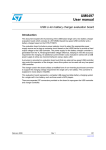
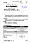
1
Wyeast Technology 354A FET Cycling Control
User Manual
manual.sxw
2004-09-24
2
1. Introduction
Power cycle testing is an important measure of long term reliability. Power
cycling repetitively stresses parts by thermal heating and cooling, straining solder
connections and other package features. In many cases a certain temperature swing is
given, such as Tj swing of 100°C. It is not an easy task to control and measure
junction temperature swing with general purpose test instrumentation. Even if the
part is characterized correctly before testing, testing itself changes thermal
parameters, and devices must be re-characterized often during a test.
2. Basic Features of the 354A
The 354A is designed to outperform current, in-house designed cycling
systems by addressing the problems of interface change and initial performance
differences noted above.
The key feature of the 354A is the combination of a cycling controller and
thermal characteristic measuring instrument. After some initial measurements on the
parts under test, the instrument is able to accurately read and record every devices
junction temperature before and after each and every power cycle. This provides a
running record of thermal interface performance, the primary figure of merit affected
by power cycle testing. Even better, the system is able to dynamically adjust power
levels for each device to maintain a controlled temperature swing. This power level
adjustment is done individually for every device, and with no manual interaction
required.
Fig. 1.1a
354A Front Panel
354A Front Panel View, With Heat Supply
manual.sxw
2004-09-24
3
2.1 Overall Function of the 354A
The 354A attaches to all leads of FET devices under test. (DUTs) It takes
power from an external DC supply (Heat Supply,) and routes it to the correct device
according to timing and test parameters. Voltage is controlled by the Heat Supply.
The 354A controls current by active control of DUT gates. A host computer
connects to the 354A to provide user interface, data collection, and dynamic
adjustment of cycling conditions. All physical timing parameters are controlled by
the 354A. This eliminates fine timing dependency on the host computer's operating
system, and allows very low jitter cycle timing and measurement triggering.
354A and Surrounding Components
2.2 K- Factor Measurement
With the host computer, and an appropriate thermometer system, the 354A
may be used to measure device K factors. The K factor is a number that relates body
Diode Forward Voltage Drop (Vd) to temperature at a given current. K factor is
needed by the system to enable measurement of DUT junction temperature, in actual
cycling and thermal characterization. Offset is also measured, enabling absolute
temperature measurements to be taken. K factor and offset are recorded by DUT
serial number, prompted from the user. The system is then able to correlate a
measured diode drop Vd with a absolute junction temperature (Tj) to be used in
further testing and data collection.
The graphical host software provides a routine for the user to make K factor
measurements, which must be done before cycling or measuring of a part starts.
manual.sxw
2004-09-24
4
2.3 Thermal Characterization
The 354A is capable of making thermal characterizations on a part, including
effective Thermal Resistance to Sink (R j-s effective ) needed for controlled cycling, as well
as Junction to Case Thermal Resistance (R j-c ) which needed for a good data sheet
specification. The units of both these characteristics is °C temperature rise per
Watt of power, °C/W.
Effective Thermal Resistance to Sink is a measurement of junction heat rise
mounted on a given heat sink, at a given power level, over a given amount of time.
in example:
A certain TO-247 part is mounted to a 20°C water cooled plate. The junction temperature
is equalized to 20°C. A power pulse of 200 Watts is applied for 5 seconds, and the
junction temperature is measured immediately after removal of power at 118 °C. R j-s
effective is then (118 °C-20°C)/200W, or 0.49°C/W. This value may then be used in future
cycling to help determine the required power level for a given temperature rise.
The 354A measures Vd on every device in testing, before and after every
power cycle. The host computer uses recorded K factor and offset to obtain junction
temperatures before and after the power cycle occurred. If the temperature difference,
(temperature swing) is too low, power level is increased in subsequent cycles. If the
swing is too high, power level is decreased. The host computer records details of
every cycle, including power level and temperature swing, actually recording
R j-s effective in testing for every DUT, for every cycle.
Internally, the 354A contains a precision current source, presently fixed at
10mA. This current source is used for every Vd measurement. Ibe fixed to 10mA.
All measurements are taken with the same test current, including K factor, offset and
in-test temperature measurements.
2.4 Power Cycling
The 354A automatically controls power cycling. Before cycling, the
graphical host software host machine will allow the user to enter certain parameters,
including:
1.
2.
3.
4.
5.
Cycle quantity
Target swing (°C)
Max Current (Amps)
Thmax (°C)
Tlmax
(°C)
manual.sxw
The number of cycles to run
Desired temp swing. Usually 100°C
The maximum current allowed for heating.
Maximum final junction temperature.
Maximum starting junction temperature.
2004-09-24
5
The host computer will then control the 354A to produce cycling of the given
temperature excursion in the given cycle time. If the 354A is not able to heat the part
through the requested swing within the maximum current limit, testing will terminate
with an error. Thmax and Tlmax are protection limits to terminate cycling if a DUT
becomes overheated, say, in the case of a fan or cooling system failure.
During power cycling, the host computer will record the cycle count, the
before and after temperature for each DUT, current and voltage applied to the part,
and a time stamp. This information is stored in a mysql database, for easy and fast
access by the host software.
manual.sxw
2004-09-24
6
3. 354A Connections
3.1 Front Panel Connections
3.1.1 DUT interface cables
The main connections on the front panel of the 354A are for the DUT interface cables.
All connection to the DUTs are made by over this single connector. The connection
is described in detail in the below with the 281-001-01 DUT cable assembly in
Section 4. 354A Accessories.
3.1.2 Current and Voltage auxiliary output connections
Two BNC style Connections are provided on the controller unit, on the lower right
hand side of the display panel. These provide analog signals corresponding to the
instantaneous heat current and voltage at the DUT. They are referenced to the digital
ground of the system, or HTP. The current signal is calibrated to 0.1V/A (measured
heat current) and the voltage output is 0.05V/V (measured heat current.) These may
be monitored with an oscilloscope or voltmeter. Be aware that these quantities may
jump through undefined values while the machine is switching between DUTs.
3.2 Back Panel Connections
A labeled photograph shows the connections on the back panel.
354A Back Panel Connections
The 354A takes power from a “Heat Supply” on the Power terminal blocks. Observe
polarity, positive is on the right, negative on the left.
Power Supply Control provides an emergency stop function. It carries a normally
closed signal from the E-stop switch to the Heat Supply. Circuitry in the Heat Supply
manual.sxw
2004-09-24
7
connector end disables the supply if the E-stop switch is pushed (opened).
AUX 5V OUT is provided to run accessories requiring 5V power. This output is
capable of 3 amps, but is not fused or protected in any way. Do not short this out, it
will probably cause no harm, but will cause the cycler to lose power.
RS232 Serial connects to a 9 pin female D-sub connector on the back panel. This
provides communications from the 354A to the host computer. Note that this
connection ties Earth ground between the host computer and the 354A. It would be
advisable to run the computer and the 354A from the same AC line circuit, to avoid
ground loop problems.
AC Line is brought in on a standard IEC line entry. The 354A uses auto ranging
supplies internally, enabling the use of any AC voltage from 110 to 240VAC. Note
that accompanying the Beta Unit (#101, ) the Heat supply and the Host Computer are
configured to take 230VAC, so it would be convenient to use the same for the 354A.
Remember, it is very advisable to have the 354A and the host computer plugged into
the same AC line circuit.
4. 354A Accessories
4.1 281-001-01 DUT Cable Assembly
The 281-001-01 DUT Cable Assembly is documented on an accompanying drawing,
which shows the cable, flying leads and connector.
The 354A provides true Kelvin connections to all leads of a power FET DUT. For
each connection, Gate, Source and Drain, there are two connecting wires Force, and
Sense. Drive current flows through the Force line, and voltage is sensed off of the
Sense line in every case, eliminating voltage drop errors from cable and switching
connections. This enables very accurate low voltage measurements to be made.
Each DUT interface module card provides a front panel connector for interfacing with
a DUT. This connector is a D-sub type 7W2 shell, with two power pins and 5 signal
pins. Power pins are used for Heat Supply high current Force to Source (negative)
and Drain (positive) 4 signal level pins are used, two for Drain and Source Sense
lines, one for Gate force, and one for Gate sense.
The 281-001-01 Cable assembly is made up for conveniently connecting a MOSFET
DUT to the 354A cycler. It provides a male connector for one end, plugging int to the
module interface card, and flying wire leads for the other, which may be soldered or
bolted onto the DUT end. These are bundled together in expandable polyester braid.
Wire colors are:
Signal
Drain Force
manual.sxw
Wire
AWG 12 (large) Black
2004-09-24
8
Signal
Wire
Source Force
AWG 12 (large) White
Drain Sense
AWG 22 (small) Red
Source Sense
AWG22 (small) Blue
Gate Force
AWG22 (small) Yellow
Gate Sense
AWG22 (small) Violet
Note that in operation, Force and Sense wires are connected at the DUT. Ensure that
this wiring is correct before starting testing, as misconnections may cause damage to a
interface module card or DUT.
4.2 910-027-01 H-Bridge Balance Adapter Board
These boards are documented in schematic 910-027-01. This description will be
more clear if the schematic is on hand.
The 354A Cycle Controller has been designed to power cycle single MOS
transistor devices. An H bridge is four MOSFETS, arranged of two in series to form
one leg, and two in series to form the other. The purpose of the 910-027 adapter
boards is to make an H-bridge appear like a single transistor to the 354A. This is
done by equalizing the current through both legs, and making the center point of each
leg approximately one half the total voltage. With ½ current and ½ voltage on each
MOSFET, each one takes ¼ the full heat power.
Voltage balancing is done using a single reference generator and two OP
Amps. R6 and R7 form the reference generator, splitting the input voltage by
Vin R7
R7 R6
Vout
16.5k/(16.5k+75k) or approximately Vin*0.18.
Amplifiers U17 G1 and G2 control the center point voltage on H bridge outputs
OUT1 and OUT2, respectively. Feedback is divided down by resistors R9 (24.3k,)
R8 (43.2k) on OUT1, giving dividing ratio of approximately 0.36. The op amp acts
to equalize its input voltages, thus it controls the voltage at OUT1 to be
approximately ½ the input voltage, to provide equal voltages on pins 3 and 2 after the
voltage dividers. Transistor Q1 acts as a high voltage amplifier to extend the range of
U17. Not shown on the schematic as drawn is a feedback cap, from Q1-C to pin 3 of
1000pF, this is needed for stability.
The voltage on center point OUT2 is controlled in the same manners, by op amp U17
G2, pins 5,6,7.
U17 requires an isolated source of 15V to function, this is provided by the DY910028-01 isolating supply. The supply takes 5V in and outputs 8 completely isolated
manual.sxw
2004-09-24
9
15V sources, which actually range from 22V open circuit to around 16V when loaded.
910-028-01 isolating supply may take 5V from an auxiliary connector on the back of
the 354A unit, (serial #101.) See the Back Panel Connection Drawing for location.
4.2.2 Cable Connection to the 910-027 boards
The 910-027-01 boards have already been connected to DUT interface cables. The
connection uses a single 2 position terminal block,
4.2.3 Checking the 910-027 boards
The 910-027 boards are required for cycling H-bridges. They may be checked simply
by measuring voltage from OUT1 and OUT2 to ground, these should be
approximately ½ the total voltage on the part. This voltage may be adjusted by
trimming resistor R6, however, this is not an easy task.
4.3 281-003-01, Debug Switch Assembly
The 281-003-01 Debug switch assembly is used for re-programming the internal
software of the 354A controller unit. It consists of a toggle switch and pushbutton
switch, wired to a small 5 pin pocket header, described as followed.
281-003-01
Debug cable for 354A cycler.
Currently, this is a free hanging cable to bring out the
controller RESET and PSEN signals. These are used
with a switch and pushbutton to reprogram the controller.
A shrouded header is heat shrunk to the cable... which is cat 5
4 pair wire
pin 1 /PSEN
pin 2 DGND
pin 4 DGND
pin 5 RESET
blue of blue/white
white of blue/white
white of orange/white
orange of orange white.
The toggle switch is wired to the /PSEN signal, the pushbutton is wired to the
RESET.
See directions below in Section 5 for flashing the Controller Software.
5. “Flashing” the 354A Controller Software
5.1 Controller Code
The 354A controller uses a microcontroller to provide all control and communication.
This microcontroller is flash programmable over the same serial port used for normal
host/controller communications. Wyeast Technology may send software upgrades
with instructions to “flash” the new version into the controller. The controller should
manual.sxw
2004-09-24
10
not be flashed w/o specific instructions and an upgrade file.
5.2 Cautionary statement
The 354A must not be connected to an energized heat supply while flashing the code.
Connection to heat power could damage the 354A, as it is not in operational mode
when being programmed. The supply should be disabled, or ideally, off, before
proceeding with flash upgrades.
5.3 Upgrade file name
The name of the upgrade file to be programmed into the controller is always
cycle.hex. Wyeast Technology will place this file into the proper directory. The
customer should check to be sure the date of this file is as expected.
5.4 Flashing procedure.
a. stop any running tests and ensure that the heat supply is off.
b. exit the host control software.
c. attach the 281-003-01 debug cable assembly to the debug connector, just under the
AUX 5V out connector on the back panel, and free hanging. This connector may
be left inside the 354A unit, if so, unplug the AC line power before removing the
chassis cover to extract it. Never trust a single pole switch to truly disconnect AC
line power.
d. double check the heat supply is off. Flick the toggle switch to “P”, then reset the
controller with the pushbutton. It is now in “programming” mode.
e. send the upgrade code to the controller by running the program “aprog” from a
command line shell in /home/tester.
f. flick the toggle switch back away from “P” and reset the controller again using the
pushbutton. The 354A is now back in normal run mode.
g. remove the debug cable assembly and store in a safe place.
h. re-start the host GUI software, in its startup text window, it should report the new
software version. This should be verified against the information sent by Wyeast
Technology along with the upgrade file.
manual.sxw
2004-09-24
11
6. CycWin 354A Host Software
6.1 Software Introduction
Software running on an attached Host Computer handles all control and data logging
features of the 354A. This software runs and monitors the 354A FET Cycle
Controller and logs all data into a flexible database for reporting and analysis. It uses
a Graphical User Interface (GUI) for ease of use and clarity.
6.2 Logging in and Starting the Software
Login to the host computer (“checker”) with the user name “tester.” The password
for user tester as delivered is “test354” Start the Host Software GUI either with the
desktop shortcut “CycWin 354A Host Software,” or from terminal shell by clicking
on the “Terminal Shell” and running the script “CycWin” from the shell prompt. If
run from a Shell, useful debugging information will appear in the text terminal along
with the GUI.
The CycWin Host Software starts with a main window:
CycWin Software Main Panel
From this window, the user may chose to enter part information, stop or start a test.
6.3 Create and Edit Parts
Part information must be entered before starting a test.
To do this, click on the :
button.
This will open another screen, the create/edit parts Window:
manual.sxw
2004-09-24
12
Create/Edit Parts Window
To create a new part, click the
button, which will open up a
screen allowing the user to enter new parts:
The Part Name field ought to be
filled in with serial number, the
part number should be the lot
code and part type.
A short description must also be
entered.
If the K-factor information is
known it may be entered. If KNew Part Definition Window
factor data is not known, the
software provides a routine for the user to determine it, using the 354A. K factor data
must be known before testing of a part. This is the only way the machine can
determine the before and after temperatures.
If an error is made in part data entry, highlight the corresponding row in the
Create/Edit Parts window by clicking over it. Then use the “delete” button to remove
the row.
6.4 Determining K-Factor
After creating the parts in the previous screen, a routine may be run to determine K
factor. This is selected by the
button from the main
startup window.
manual.sxw
2004-09-24
13
A K-factor instruction window will appear:
K-Factor Instruction Window
It is critical to hook up the parts exactly as described. When the instructions say
“Tag,” here, they mean DUT channel. Thus, “Tag 1” refers to DUT channel 1, “Tag
2” refers to channel 2.
Read the instructions, check the parts are hooked up to the correct DUT channel card,
and press the “Next->” button. The K factor taking window will then show up:
It is critical that all parts selected be at the same temperature... this may be
accomplished by attaching them all to the same “isothermal block,” a large block of
copper that maintains the same temperature across its entire volume.
A thermocouple should be placed directly on the mounting tab of the device
measured. It is important to get the temperature of the semiconductor die, as
accurately and as stable as possible when making K factor measurements. The 354A
can be no more accurate than the K factor measured.
manual.sxw
2004-09-24
14
Heat the DUTs together in an oven or a carefully controlled d hotplate. Ensure than
however they are heated, you are able to take a stable measurement at close to the
requested temperatures.
When the part is stabilized at approximately 25°C, enter the exact temperature
measured in the fill in box on the left, and click the “measure at approximately
25°C” button. This will probably be room temperature.. just ensure that that the parts
are well stabilized (not warming or cooling.) and that the measurement typed into the
window is the actual temperature when the button is pressed.
Heat the part and stabilize at approximately 60°C. Again enter the measured
temperature and click the “measure at approximately 60°C” button. It is not critical
what the exact temperature is, so long as it is measured accurately and entered
correctly.
Repeat for the 95°C measurement. The software will then run a linear regression to
determine K-factor and offset for the part. The information from the k-factor
determination procedure is saved in the system database.
Devices of identical size from the same wafer lot generally have very close to the
same K factor. You may decide to take K-factor on a sample of parts only, and copy
in data part to part using the “K factor (if known)” option in the New Part Definition
Window.
manual.sxw
2004-09-24
15
6.5 Starting a Test
Once part numbers have been entered, and K-factors have either been measured or
entered, a test may be started. Select the
from the main
window.
A panel will appear asking the operator to select parts to test. Selected parts are
highlighted by clicking with the mouse, and using ctrl-click or shift -click to add to
the selection. Ensure the correct parts are selected, and hooked up exactly as
instructed in the window appearing next. All data logging is dependent on the fact
that the correct devices are hooked up to the correct DUT channels.
Highlight parts with
mouse to select.
Select Parts for Test Window
manual.sxw
2004-09-24
16
The software will allow the user to chose which part gets connected to which DUT
interface. Just click in the Position Number field to change this number. You must
select a different position for each DUT.
Select Position for Test Window
Be sure to hook up the parts exactly as listed in this screen.
Next, fill in the
information requested
by the Test Limits
Entry window. Full
temperature refers to
the temperature swing
the test will shoot for.
Default temperature
swing is 100C, default
number of cycles is
10,000... but this may
be changed by the
user.
Test Limits Entry Window
Saved reports will be grouped into subdirectories by project. To change the project,
use the pull down selection in the “select project for test” box. Projects must have
already been created using the create/edit projects button on the main panel.
manual.sxw
2004-09-24
17
Start Test Confirmation Window
Finally, a window will appear asking the user to confirm the limits and part hook up
order, then to start the test. If anything is wrong, correct by using the “<-Prev”
button or Cancel. The user should carefully double check wiring and test limits
before starting the test.
manual.sxw
2004-09-24
18
6.6 Test Action
Parts will be cycled in order. As heating current is applied to a part, the green
“Channel” indicator LED is lit up on the corresponding module card. These should
stay lit for 4 seconds before the next unit is energized.
The test will presently start at zero heat current commanded, and slowly ramp up until
the target swing has been reached. The user should monitor the test until it has
reasonably stabilized, and ensure cooling is properly functioning.
The host software queries the 354a on every cycle, calculating temperature swing. If
the swing is to high, it reduces heat current command. If the swing is too low, the
heat current command is increased. It will take several tens of cycles before the
temperature swing is truly stabilized... this may be improved for faster convergence in
the future.
Data is logged to an SQL database
residing on the host machine. One
report function is currently
implemented in the host control
software.
To access this report
generator, select the “Reports” tab
from the top of the 354A host
control window, then chose the
desired project and test name. A
message will then appear with the
location of the file created:
You may select the number of rows
to go into the comma delimited file.
For example, if there are 5000 cycles taken, and the user asks for 500 rows, the
software will select every 10th row to export.
This report file contains comma delimited data tabulated for each DUT, organized in
separate columns for each part, making it convenient for comparisons between
devices under test.
manual.sxw
2004-09-24
19
6.7 Rtj-c/Rtj-s Testing
The 354A may be used for Rtj-c and Rtj-s measurements on characterized
FETs. Rtj-c and Rtj-s measurements require measurements of junction
temperature, device case temperature, and sink temperature.
Thermal resistance measurements are important for datasheet
characterizations. Designers use Rtj-c and Rtj-s numbers to design
cooling systems that provide adaquate cooling to a semiconductor in an
application.
6.7.1 Definition of thermal resistance
Thermal resistance can be loosely defined as the opposition of a region to
heat flow. An analogy to electrical circuits can be drawn, with
temperature differences substituted for voltage, and heat flow (power)
substituted for current:
T1 T2
Power
Rt
in units of °C/W
T1 – T2 is the temperature differnce across the region in interest.
In our case, for junction-to-case thermal resistance:
Tj Tc
Power
Rtjc
°C/W
and for junction-to-sink thermal resistance:
Tj Tsink
Power
Rtjc
°C/W
Junction temperature of a part is measured in the same manner as the
354A uses to track temperature swing during cycle testing, by voltage
drop at a given test current over the DUT's integral body diode.
manual.sxw
2004-09-24
20
6.7.2 Use of Heat Block
Case and sink temperature may be measured using a special copper “heat
block” which provides thermocouples measuring the block's own “sink
temperature” and the temperature of the mounted DUT directly below the
semiconductor die. Case, sink and junction temperature should be
measured simultaneously. In practice, measuring maximum temperature
on the case and sink, and taking a thermal measurement immediately after
a heat pulse gives good results.
In the picture above, the Tc case thermocouple can be seen protruding a
small amount over the surface of the copper heat block. This
thermocouple is isolated from the copper by a small insulator fit into the
hole. The case thermocouple must protrude enough to put gentle pressure
on the metal of the DUT case.
Water is used as a thermally conductive media in Rtj-c testing. Water
pulls itself between the part and the block by capilary action, greatly
improving thermal contact. Thermally conductive grease would work,
but be very messy to clean up and deal with.
It is important to correctly position the DUT over the case reading
thermocouple. The thermocouple must touch the case directly under the
semiconductor die mounted in the package.
manual.sxw
2004-09-24
21
The DUT should be securely clamped down to the heat block during Rtj-c
testing for repeatable results. Good physical mounting is very important
to get accurate values in this test. The heat block should be secured to a
cooling plate with water running.
6.7.3 Host Software Operation for Rtj-c testing
Host software provided with the 354A supplies an Rtj-c measuring
routine. Select
from the main System Control panel. This will open the Rtj-c measuring
screen:
Just as in setting up cycle testing, it is critical that the correct, well
charcaterized part is selected, and that it is on the correct DUT (tag)
channel. Parts and position are selected by the pull down menus in the
upper left of the panel.
Chose a heating current enough to bring the part up to good operating
manual.sxw
2004-09-24
22
temperature. This should probably be close to the test current the part
runs in cycle testing, to give the part a swing of 100C.
Pulse duration is limited to 12 seconds at this point. There is no reason to
use a shorter time than the default12 seconds, and it may impact accuracy
to do so.
Set a thermocouple thermometer to measure maximum temperature on
both Tc and Ts thermocouples, in °C. The maximum temperature will
occur right before pulse termination, which is when the junction
temperature is measured by the 354A.
Click the
button to start the heat pulse. The 354A will then time and control a
pulse, with current slightly under the “Approx. heat current” requested on
the panel.
When the pulse has terminated, read the maximum temperatures from the
thermometer and fill them in in the boxes provided on the right side of the
panel:
manual.sxw
2004-09-24
23
Then click the
Rtj-s values.
button to calculate Rtj-c and
These may be added to the database by clicking
The host software will prompt for some descriptive text to add as a
comment to that specific test instance. The measurement will be added to
the table rt_measurements when “OK” is clicked.
manual.sxw
2004-09-24
24
7. Calibration Procedure
The 354A is calibrated at the factory, and user calibration is ordinarily not
recommended. Mistakes in calibration may lead to incorrect data, and improper
calibration procedure could possibly damage the Beta unit 354A.
7.1 Calibration Concepts
The 354A makes three critical measurements:
Diode Forward Voltage (Vd,) which corresponds to DUT temperature.
Heat Voltage (Vheat)
Heat Current (Iheat)
These measurements are made by the central controller, using the same analog
hardware and analog to digital conversion for each DUT. This results in only one
calibration being valid for all DUTs; it is convenient to do this with DUT #8,
especially in calibrating Diode Forward Voltage.
The hardware is assumed to be linear. Two calibration numbers are supplied for each
measurement, offset, and scale. The host records data as:
measurement = (raw)(scale) + offset
where raw is the data directly from an analog to digital conversion, scale and offset
are numbers to convert this into a engineering unit quantity.
These calibration numbers are determined by taking data under two different test
conditions.
Calibration numbers are stored in the file 354a.conf. If needed, this file is edited
to insert new calibration numbers.
A spreadsheet is available to do the calculations for calibration. Without this, the
these calculations would be tedious and very error prone. The raw ADC (unscaled)
data is not accessible to the user, and must be back-calibrated from reported values
and current calibration numbers in use.
7.2 Calibration Equipment
Suggested calibration equipment should be on hand before starting calibration:
1.
2.
3.
4.
text editor on host computer
Spreadsheet calibration_worksheet.sxc
Calibrated voltage meter with clip leads (34401A is ideal)
Calibrated current meter capable of 10 amps, with heavy clip leads
manual.sxw
2004-09-24
25
5.
6.
7.
8.
Extra DUT cable or male connector
Schottky Diode and small clip leads
Ordinary MOSFET DUT
Current limiting heat supply
7.3 Vd Calibration Procedure
Vd will be calibrated by measuring at two separate points. It is convenient to have a
Schottky diode to simulate a DUT at high temperature. This will eliminate the need
to stabilized the DUT at two different temperatures.
a. Open the 354a Host
Control software and switch
to the Admin Panel using the
top tabs.
a. Open spreadsheet calibration_worksheet.sxc, using OpenOffice
b. Open file 354a.conf in a
text editor such as vi or kwrite.
c. Copy the existing calibration numbers calibration.Vd_offset and
calibration.Vd_scale into the spreadsheet cells labeled Vd_offset and Vd_scale, cells
B6 and B7. Locations for user input are denoted by a blue background.
manual.sxw
2004-09-24
26
Calibration Worksheet, Vd section
d. Attach the voltmeter leads to DUT#8, Source and Drain leads. If the meter is
properly calibrated, it is not necessary to orient these leads to always read positive
voltage.. just enter positive voltages only in the Calibration Worksheet.
e. Clip the Schottky diode in
parallel with DUT#8. The diode's
cathode is connected to DUT8's
Drain lead, the diode's anode is
connected to DUT8's Source lead.
In this way, the diode is
effectively in parallel with the
internal body diode of DUT8.
f. From the Admin Panel, click
Schottky Diode in Parallel with DUT, with voltmeter
the force measurement button.
leads attached
Measurements will appear in the
shell window. Immediately read
the attached voltmeter for the actual diode voltage. A hold function is usefull here.
Copy the voltmeter reading into cell B10. It should be much lower than an ordinary
diode drop.
Copy the last DUT8 measurements from
the shell window into the spreadsheet cells
C, D, and E10. In the picture here, these
are 0.2744, 0.2744, 0.2744..
Shell output from "force data"
manual.sxw
2004-09-24
27
g. Remove the paralleled Schottky and repeat the process to get a sample of ordinary
room temperature DUT diode drop. Insert these values into row 11 in the
spreadsheet.
h. The new calibration values are in cells B14 and B15. Edit the 354a.conf file
(values calibration.Vd_offset, and calibration.Vd_scale to update these.
7.4 Vheat Calibration Procedure
Vheat will be calibrated in the same way, by measuring at two separate points. To
get the two points, an adjustable Heat Supply must be connected to the 354a. This
procedure will use the “pulse device” function to apply voltage, but not current to the
DUT.
It is convenient to remain with DUT#8. Leave the voltmeter attached, but be sure to
check the Schottky diode is removed.
a. Open file 354a.conf in a text editor such as vi or kwrite.
b. Copy the existing
calibration numbers
calibration.Vh_offset and
calibration.Vh_scale into the
spreadsheet cells labeled
Vh_offset and Vh_scale, cells
B24 and B25. Locations for
user input are denoted by a
blue background.
Calibration Worksheet, Vh Section
c. In the Admin Panel , right hand side, chose “select D.U.T. #8”. Enter the value 0
(zero) into the white DAC setting box, and click the button write DAC. The shell
window should respond “wrote 0x0 to D.U.T. 8 (response=0x0). This will set the
current command to 0, where it will not cause the applied voltage to drift while the
calibration shot is in process.
b. Adjust the heat supply for an output voltage of approximately 8V.
c. Observe the voltmeter, and click the pulse device button. Read the value on the
voltmeter when the voltage is stabilized. Ideally, the meter should be read two
seconds after the pulse goes into effect (green channel light on DUT module,) but the
results will be fine as long as the heat supply is stable. Record the voltmeter reading
manual.sxw
2004-09-24
28
(actual heat voltage) into spreadsheet cell B28.
d. Click the “read cycle data” button on the left bottom of the Admin Panel. Cycle
data will scroll into the shell window. Read the reported V_heat measurement for
DUT 8.
Cycle Data Scrolled Into Shell Window
For example, the value read here is V_heat=8.0923. 8.0923 would be entered into
spreadsheet cell C28.
e. Repeat this process at a higher heat voltage (ideally a little over the actual DUT
heating voltage used for testing) to get information for spreadsheet row 29, the
vheat2 calibration sample.
f. The new calibration values are in cells B32 and B33. Edit the 354a.conf file
(values calibration.Vh_offset, and calibration.Vh_scale to update these.
manual.sxw
2004-09-24
29
7.5 Iheat Calibration Procedure
The Iheat calibration is done almost exactly like the Vheat calibration. It uses the
current limit of the power supply to provide two separate test currents, instead of test
voltages.
a. Copy the existing calibration numbers calibration.Ih_offset and
calibration.Ih_scale into the spreadsheet cells labeled Ih_offset and Ih_scale, cells
B43 and B44.
b. Turn the heat voltage supply down to about 4 volts, and set the current limit for
approximately 3A. It is very important to have the voltage backed down to a low
level or the output capacitance of the supply may deliver a damaging spike into the
interface module cards.
c. Remove DUT 8, and attach a current
meter. Current should flow FROM DRAIN
FORCE into the + of the meter, out the – and
back into the SOURCE FORCE. A spare DUT
cable is handy for this, simply connect the
meter to the large white and black heat
current force leads. In the picture to the right,
a meter is attached to an open male connector
plugged into the interface module. It is not
necessary to connect any other leads to the
interface module card.
Current Meter Attached to Drain Force and
Source Force
d. Observe the meter and click the pulse device button. Read the current meter when
the heat current has stabilized, and record it in spreadsheet cell B47, Actual Current
read from Meter for Iheat calibration shot # 1.
e. Click the read cycle data button and read the I_heat measurement for DUT #8.
Enter this in spreadsheet cell C47.
f. Adjust the heat current limit up to a higher level (10 A works well,) taking care
not to exceed current ratings on the meter and test leads used. Repeat steps c
and d to fill in spreadsheet row 48, for calibration shot Iheat 2.
g. The new calibration numbers are in cells B51 and B52, and should be updated into
the 354a.conf file for calibration.Ih_offset and calibration.Ih_scale.
manual.sxw
2004-09-24
30
8. Thermal Error Stackup
8.1 Thermal Error
Several factors influence the repeatability and accuracy of the 354a. What follows is
a consideration of the most important errors affecting the Vd measurement, which is
used to calculate both absolute temperature and temperature swing.
Assuming the machine has been calibrated, and all uncertainty comes from thermal
drift properties of the differential amplifier, ADC and reference voltage and that the
internal operating temperature of the 354A runs 25°C to 50°C (a 25°C delta)
Gain Errors:
reference error (on board controller uC) ±100ppm * 25°C = 1± 0.0025 (ref error)
gain setting resistor (100ppm/°C )on differential input amplifier:
nom: 26.1k
max : 26.1k * (1+.0001*25) = 26.165k
min: 26.1*(1-.0001*25) = 26.034k
gain setting equation is 49.4k/Rset + 1, therefore gain is
nominal: 2.89272
max: 2.89746
min:
2.88800
gain error due to gain setting resistor is approximately 1±.00163 (gain set err)
gain error due to amplifier is: 50ppm/ °C , or 25*.00005 = 1±.0.00125 (gain err)
These gain errors total to a maximum of 1.00539, or 1±.0.539% gain.
With a 100 °C swing, the gain induced error could be as high as ±.0.539°C.
DC accuracy value on the ADC is specified at 3 “LSBs” A LSB is nominally
2.5V/4096 counts, so this leads to an uncertainty of 0.00183V. The effect of this is
reduced by the differential amplifier's nominal gain of 2.89272, for a diode voltage
uncertainty contribution of 0.0006330. Given a “k” factor of 2.00mV/°C, this leads to
a temperature uncertainty of ±.0.317°C. With the above gain calculation, the
measurement could be said to have error in the range of ± 0.856°C, if all these factors
stacked up in the worst possible combination.
Effects of thermally induced errors can be minimized by allowing the machine to
warm up before calibration and use. It is also advisiable to measure DUT K-factors
and offsets on the 354, rather than using other measurements, as this will eliminate
absolute accuracy issues in the thermal measurement path.
manual.sxw
2004-09-24
31
9. Data Base Structure
9.1 354A System Data Storage Overview
During normal cycling operation, the Host Computer logs all measured heat
quantities (voltage and current) and thermal measurements. The Host Computer
calculates actual quantities from the raw data sent by the 354A cycler, using
calibration values in the configureation file.
All data is written to a database, currently using MySQL residing on the host
machine. The host software is also capable of writing to a network accessible Oracle
database, if the tables are correctly set up.
9.2 Description of Tables
As shipped 2003-08-28, (unit 780102) the database name is dynalink_354a.
are:
table name
Tables
description
cycledata
all logged data for each cycle, each part
kfactor_measurements
K-factor measurement storage
parts
description of part, including calculated or entered K factor data
projects
project name and ID
tests
description of tests, including which DUT channel is connected to which
part.
Tables of Database dynalink_354a
column name
description
fk_tests
the test ID number (keys to tests table.)
fk_parts
the part ID number (keys to parts table.)
cycle_num
cycle count number
T_before
temperature before heat pulse, in °C, calculated by Host from diode
forward drop using K-factor and offset from parts data.
T_after
temperature after heat pulse
vd_before
forward diode drop before heat pulse (average of 3 from 354A)
vd_after
forward diode drop after heat pulse (average of 3 from 354A)
v_heat
heat voltage measured by 354A
i_heat
heat current measured by 354A
Columns of table cycledata
manual.sxw
2004-09-24
32
column name
description
fk_parts
the part ID number (keys to parts table.)
Vd
measured forward diode drop (average of 3 measurements sent by 354A)
temp
temperature that measurement was taken at
date_measured
the date and time the measurement was taken
notes
presently unused.
Columns of table kfactor_measurements
column name
description
ID
part ID number, ref'd by fk_parts in other tables.
part_name
user entered name for part (from create parts window)
part_number
user entered number for part
part_description
user entered description
date_entered
date and time the part was created by user
k_factor
k_factor calculated by routine or entered during part creation
k_offset
offset calculated or entered.
Columns of table parts
column name
description
ID
test ID number, ref'd by fk_tests in other tables.
test_name
user entered test name, from start test window
description
user entered test description
fk_parts_dut1,
8 columns. Each “dut” column contains the part ID number, which
references the part ID in the parts table. This “connects” the part names to
the DUT channels.
fk_parts_dut2, ...
fk_parts_dut8
fk_projects
which project this test is a member of. New projects are created in the
main window with the edit/create project button.
starttime
time the cycling test started.
stoptime
time the cycling test ended. (not implemented yet.)
Columns of table tests
manual.sxw
2004-09-24
33
column name
description
ID
project ID number, ref'd by fk_projects in other tables
name
project name
The projects table may store more detailed information in the future.
Columns of table projects
9.3 As-Shipped Database information.
If a user is fluent in SQL database queries, they may find it useful to directly pull data
from the database. This can be a very fast way of determining the condition of parts
currently under test, as well as sorting out and selecting subsets of data.
Wyeast Technology does not recommend changing table structure or adding data to
the database independent of the normal host control software.
Host system accompanying 354A serial number ______________
was shipped with host system passwords
system user cycler
_______________
MySQL root password
_______________
MySQL user cycler, password _______________
manual.sxw
2004-09-24
34
manual.sxw
2004-09-24