1
UM0497
User manual
USB Li-Ion battery charger evaluation board
Introduction
This document explains the functioning of the USB-based single cell Li-Ion battery charger
evaluation board which consists of a ST7260E2-based low-speed USB controller and a
battery charger based on the ST7LIT15BY0.
The evaluation board includes a power selector circuit to select the appropriate power
supply source and a step-up converter circuit based on the L6920 device to provide a fixed
output voltage to the USB controller. The power supply for the battery charger controller is
generated from the TL1431programmable voltage reference, keeping in mind the accuracy
requirement for charging. An additional current limiter is also included in series with a USB
power supply to show any incorrect behavior using a status LED.
A provision is provided on evaluation board such that any external low-speed USB controller
can control the operation of the charger, hence this system can be used with any low-speed
USB controller.
The charger used in the board utilizes a modified form of non-inverting buck-boost converter
to support the charging voltage requirement for single cell Li-Ion battery. This converter is
explained in more detail in AN2390.
This evaluation board represents a complete USB-based portable battery charging system
for a single cell Li-Ion battery, such as those used in MP3 players.
There are separate ICP connectors provided on the board to reprogram the USB controller
and charger controller.
February 2008
Rev 1
1/21
www.st.com
Contents
UM0497
Contents
1
2
Getting started . . . . . . . . . . . . . . . . . . . . . . . . . . . . . . . . . . . . . . . . . . . . . . 4
1.1
Package contents . . . . . . . . . . . . . . . . . . . . . . . . . . . . . . . . . . . . . . . . . . . . 4
1.2
Hardware description . . . . . . . . . . . . . . . . . . . . . . . . . . . . . . . . . . . . . . . . . 4
1.2.1
Power supply . . . . . . . . . . . . . . . . . . . . . . . . . . . . . . . . . . . . . . . . . . . . . . 4
1.2.2
Current limiter (ST890B) . . . . . . . . . . . . . . . . . . . . . . . . . . . . . . . . . . . . . 4
1.2.3
Precision supply for the charger . . . . . . . . . . . . . . . . . . . . . . . . . . . . . . . 5
1.2.4
Preferential power selector circuit . . . . . . . . . . . . . . . . . . . . . . . . . . . . . . 5
1.2.5
Supply generation circuit for the USB controller . . . . . . . . . . . . . . . . . . . 6
1.2.6
Supply shutdown control circuit for the USB controller . . . . . . . . . . . . . . 6
1.2.7
Jumpers and connectors . . . . . . . . . . . . . . . . . . . . . . . . . . . . . . . . . . . . . 6
1.2.8
DC-DC converter circuit . . . . . . . . . . . . . . . . . . . . . . . . . . . . . . . . . . . . . . 8
Running the evaluation board . . . . . . . . . . . . . . . . . . . . . . . . . . . . . . . . . 9
2.1
Connecting to the PC . . . . . . . . . . . . . . . . . . . . . . . . . . . . . . . . . . . . . . . . . 9
2.2
Connecting the Li-Ion battery . . . . . . . . . . . . . . . . . . . . . . . . . . . . . . . . . . 10
2.3
Battery charging status monitoring . . . . . . . . . . . . . . . . . . . . . . . . . . . . . . 11
2.4
Controlling/changing the charging parameters . . . . . . . . . . . . . . . . . . . . . 11
3
Using the external USB controller . . . . . . . . . . . . . . . . . . . . . . . . . . . . . 13
4
Using the charger in standalone mode . . . . . . . . . . . . . . . . . . . . . . . . . 14
5
Warning/limitation . . . . . . . . . . . . . . . . . . . . . . . . . . . . . . . . . . . . . . . . . . 15
6
Reference . . . . . . . . . . . . . . . . . . . . . . . . . . . . . . . . . . . . . . . . . . . . . . . . . 15
Appendix A Schematic . . . . . . . . . . . . . . . . . . . . . . . . . . . . . . . . . . . . . . . . . . . . . . 16
6.1
7
2/21
USB battery charger BOM . . . . . . . . . . . . . . . . . . . . . . . . . . . . . . . . . . . . 17
Revision history . . . . . . . . . . . . . . . . . . . . . . . . . . . . . . . . . . . . . . . . . . . 20
UM0497
List of figures
List of figures
Figure 1.
Figure 2.
Figure 3.
Figure 4.
Figure 5.
Figure 6.
Figure 7.
Figure 8.
Figure 9.
Figure 10.
Figure 11.
USB Li-Ion evaluation board (STEVAL-ISB003V1) . . . . . . . . . . . . . . . . . . . . . . . . . . . . . . . 4
Reference voltage generation for the charger . . . . . . . . . . . . . . . . . . . . . . . . . . . . . . . . . . . 5
Power selector circuit . . . . . . . . . . . . . . . . . . . . . . . . . . . . . . . . . . . . . . . . . . . . . . . . . . . . . . 5
Supply generation circuit for the USB controller . . . . . . . . . . . . . . . . . . . . . . . . . . . . . . . . . . 6
Connector J2 . . . . . . . . . . . . . . . . . . . . . . . . . . . . . . . . . . . . . . . . . . . . . . . . . . . . . . . . . . . . 7
Clock selector . . . . . . . . . . . . . . . . . . . . . . . . . . . . . . . . . . . . . . . . . . . . . . . . . . . . . . . . . . . . 7
DC-DC converter circuit . . . . . . . . . . . . . . . . . . . . . . . . . . . . . . . . . . . . . . . . . . . . . . . . . . . . 8
Enumeration result . . . . . . . . . . . . . . . . . . . . . . . . . . . . . . . . . . . . . . . . . . . . . . . . . . . . . . . . 9
USB Li-Ion evaluation board HID . . . . . . . . . . . . . . . . . . . . . . . . . . . . . . . . . . . . . . . . . . . . 10
Li-Ion battery 3-pin connector . . . . . . . . . . . . . . . . . . . . . . . . . . . . . . . . . . . . . . . . . . . . . . . 10
Schematic . . . . . . . . . . . . . . . . . . . . . . . . . . . . . . . . . . . . . . . . . . . . . . . . . . . . . . . . . . . . . . 16
3/21
Getting started
UM0497
1
Getting started
1.1
Package contents
The USB Li-Ion battery charger evaluation board includes the following items:
●
Hardware content:
–
●
–
1.2
One evaluation board
Documentation:
User manual
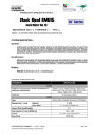
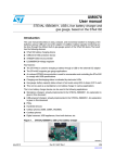
Hardware description
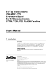
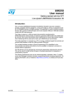
Figure 1 below shows the snapshot of the evaluation board.
Figure 1.
1.2.1
USB Li-Ion evaluation board (STEVAL-ISB003V1)
Power supply
The evaluation board is powered by a USB bus directly. As only 100 mA current is available
by default from the USB bus, the charger is inititally kept in shutdown mode. After proper
enumeration is done by the USB controller to increase the supply current limit to 500 mA,
the charger switches to ON to start charging the battery.
1.2.2
Current limiter (ST890B)
To provide additional information about the USB supply current, a current limiter (ST890B) is
kept in series of the USB supply. There is a STATUS LED (D3) connected with the FAULT
pin of this current limiter.
4/21
UM0497
Getting started
This LED glows HIGH whenever the supply current increases from 500 mA. In the
evaluation board, the current limiter is used only to show the status of whether the current
limit is crossed or not, but it is not used to cut off the power supply.
1.2.3
Precision supply for the charger
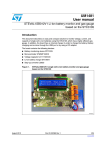
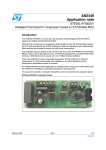
Figure 2 shows circuit for the precision supply for the charger system. Here TL1431AI,
which provides 0.25% accurate reference voltage, is used to generate a precise voltage
supply for the charger system.
Figure 2.
Reference voltage generation for the charger
With the help of this precision supply, we can easily achieve the 1% accuracy target which is
mandatory for Li-Ion charger systems.
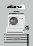
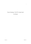
1.2.4
Preferential power selector circuit
Figure 3 shows a preferential power selector circuit which is used to select the source power
supply for the USB controller.
Figure 3.
Power selector circuit
This selector circuit works as follows. Whenever the USB supply (VBUS) is available, it is
used as the source supply. Battery power is only used when the USB supply is not available.
5/21
Getting started
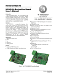
1.2.5
UM0497
Supply generation circuit for the USB controller
Figure 4 shows L6920-based supply generation circuit for the USB controller. USB_SUPPLY
is the output voltage and VREG (output voltage of the power selector circuit as in
Section 1.2.4) is the input voltage of this circuit. The output voltage USB_SUPPLY is
programmable. In the evaluation board it is set at 4.5 voltage and depends on the ratio
R4/R9. Please refer to the L6920 datasheet for more details.
Figure 4.
Supply generation circuit for the USB controller
LED (D4) is used to show the status of the input supply availability which glows whenever
the input supply falls below a certain threshold (determined by the voltage at LBI).
1.2.6
Supply shutdown control circuit for the USB controller
The STM1061 as shown in Figure 4 is used to control the shutdown operation of the L6920.
It puts the L6920 in shutdown mode whenever the input supply voltage falls below 2.5 V.
1.2.7
Jumpers and connectors
The following important jumpers control the operation of the evaluation board and are
explained according to their applications:
J2, JP1, JP3, JP12, JP13, JP14 and JP16 are used to select between the USB controller
available on the evaluation board and the external USB controller.
6/21
UM0497
Getting started
The role of each individual jumpers is as follows:
●
JP1: to connect USB_SUPPLY to the VDD pin of the USB controller
●
JP3: to connect USBVCC to USBDM through a 1.5 kΩ resistor.
●
JP12: to monitor the availability of the VBUS signal.
●
JP15: to connect to the SHDN_CHG pin of the charger. This is used to put the charger
in shutdown mode until proper enumeration is done.
●
JP13, JP14: These are used to connect to the status pin
●
JP16: to connect the USB supply pin to the demonstration board supply pin. Pin 1 of
this jumper is the USB supply pin (USB_VDD) and pin 2 is the demonstration supply pin
(VBUS). For the standalone charger, please connect the external supply to pin 2 of
JP16.
●
J2: As shown in Figure 5, this is a 7-pin connector and can be used to connect to the
external USB controller.
Figure 5.
Connector J2
Warning:
You can connect to only one USB controller at a time. If you
want to use an external USB controller, you must open all the
jumpers (JP1, JP3, JP12, JP13, JP14 and JP15) required by
the USB controller.
J5 and J7: These are 3-pin connectors and are used to select between the ICC clock and
resonator clock. J5 is used for selecting the clock source for the USB controller (ST7260E2)
available in the evaluation board and J7 is used to select the clock source of the charger IC
(ST7LIT15BY0). As shown in Figure 6, if we short pin 1 and 2 then the external resonator is
used as the clock source and if we short pin 2 and pin 3, ICC clock is used as the clock
source. In general we short pin 1 and pin 2.
Figure 6.
Clock selector
7/21
Getting started
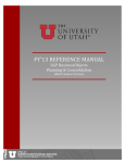
1.2.8
UM0497
DC-DC converter circuit
Figure 7 shows the circuit diagram of the DC-DC converter circuit which is controlled by the
two PWM signals coming from the charger controller ST7LIT15BY0.
Figure 7.
DC-DC converter circuit
This DC-DC converter provides power to the single cell Li-Ion (3-pin battery pack) based on
the battery voltage, current and temperature measurements. Please refer to AN2390 for
more details regarding this DC-DC converter circuit.
8/21
UM0497
2
Running the evaluation board
Running the evaluation board
After ensuring that all the jumpers are connected correctly as explained in the previous
section, the evaluation board is ready to be used.
2.1
Connecting to the PC
As soon as you connect the USB connector to the evaluation board, you should find the
evaluation board enumerated as an HID device as shown Figure 8.
Figure 8.
Enumeration result
And if you check the properties of all these HID devices, you should find the property of one
HID device as shown in Figure 9.
9/21
Running the evaluation board
Figure 9.
UM0497
USB Li-Ion evaluation board HID
This ensures that the evaluation board is connected properly to the USB and now ready to
be used. Now we can proceed to the next steps.
2.2
Connecting the Li-Ion battery
The evaluation board is not provided with any specific slot in order to avoid making it
package specific. Instead a 3-pin connector is provided on the evaluation board as shown in
Figure 10.
Figure 10. Li-Ion battery 3-pin connector
You can either solder a particular slot to this connector and then connect the battery in that
slot, or if you are directly connecting the battery to the connector, please ensure that the
battery is properly connected as improper connection may affect the accuracy of the analog
measurement, thus affecting the overall accuracy of the charging.
10/21
UM0497
2.3
Running the evaluation board
Battery charging status monitoring
There are two LEDS available (D8 and D9) on the evaluation board. Table 1 explains the
behavior of these status LEDs according to the charging status.
Table 1.
Note:
Charging LED status
SL NO
Charging status
Red LED (D8)
Green LED (D9)
1
Battery not present / Idle
OFF
OFF
2
Charging ongoing
ON
OFF
3
Charging done
OFF
ON
4
Error in charging
ON
ON
An error condition occurs for following reasons:
Temperature (heat or cold condition)
Short-circuit
Bad battery when the impedance of the battery becomes very low.
Note:
For the condition due to a bad battery, if impedance of the battery becomes very high, then
current does not flow through the battery. In this case charging is stopped and the status
LED shows that charging is done.
2.4
Controlling/changing the charging parameters
The variables inTable 2 are used to control different charging parameters.
Table 2.
Controlling/ changing the charging parameters
File name: Bc.h
Sl No
Parameter
name
Function
Formulae
Comments
1
LION_VF_H
To define constant voltage
threshold to fix the constant
voltage level.
t hreshold
X = ⎛⎝ ----------------------------⎞⎠ ⋅ 1024
{ 2 ⋅ 3.6 })]
For example:
X = 597 for 4.2 V
threshold.
2
LION_VFAST
Voltage to switch from pre-charge
level
t hreshold
X = ⎛ ----------------------------⎞ ⋅ 1024
⎝ { 2 ⋅ 3.6 })]⎠
For example:
X = 469 for 3.3V precharge threshold.
3
LION_VFAIL
Not used
4
LION_VF_L
Not used
5
LION_VSC
Used along with LION_TFAIL to
define bad battery condition
t hreshold
X = ⎛ ----------------------------⎞ ⋅ 1024
⎝ { 2 ⋅ 3.6 })]⎠
For example:
X = 213 for 1.5V threshold.
6
LION_VSAT
Voltage to switch from pre-charge
level
t hreshold
X = ⎛ ----------------------------⎞ ⋅ 1024
⎝ { 2 ⋅ 3.6 })]⎠
For example:
X = 469 for 3.3V precharge threshold.
11/21
Running the evaluation board
Table 2.
UM0497
Controlling/ changing the charging parameters (continued)
File name: Bc.h
7
LION_ICONST
Current level during constant
current charging
Y = CurrentThre
----------------------------------2.5
For example:
Y = 120 for 300 mA
charging current.
8
LION_ITRI_1
Constant current level during precharging phase
Y = CurrentThre
----------------------------------2.5
For example:
Y = 20 for 50 mA precharging current.
9
LION_ITRI_2
Not used
10
LION_IFAIL
Short-circuit current threshold
Y = CurrentThre
----------------------------------2.5
For example:
Y = 140 for 350 mA short
circuit current.
11
LION_ISAT
Current threshold to end charging
Y = CurrentThre
----------------------------------2.5
For example:
Y = 18 for 45 mA short
circuit current.
12
LION_VHEAT_
UP
Heat indicator threshold
⎧
R1
Z = ⎨ ----------------------------------- .
⎩ ( 10kΩ + R1 ) } 256
For example:
Z = 80 for 45 Celsius
degree temperature (Here
R1 is in kΩ).
13
LION_VHEAT_
DOWN
Cold indicator threshold
⎧
R1
Z = ⎨ ----------------------------------- .
⎩ ( 10kΩ + R1 ) } 256
For example:
Z = 195 for 0 Celsius
degree temperature (Here
R1 is in kΩ).
14
LION_TFAIL
Used with LION_VSC
15
LION_TEXP
Expiration in minutes
12/21
W=
(expected time expiration
value in minutes)
2
For example:
W = 150 for a 5-hour time
expiration.
UM0497
3
Using the external USB controller
Using the external USB controller
Before using the external USB controller, you must remove all jumpers (JP1, JP3, JP12,
JP13, JP14 and JP15). After that you need to do the connections as mentioned in
Section 1.2.7. To use the external USB controller in order to control the charging operation,
you must do the following steps:
1.
First disable the SHDN_CHG pin by making it low to switch off the charger.
2.
Do the proper enumeration of the USB cell to increase the current limit up to 500 mA.
3.
During battery charging, as the USB controller is also being powered by a USB, the
power consumption of the system should be kept at less than 150 mA, otherwise we
may not achieve the targeted 250 mA charging current.
4.
After completing steps 1, 2 and 3, enable the SHDN_CHG pin to high to enable
charging operation.
5.
Connect the battery.
6.
Start monitoring the status of the battery charging by monitoring the status pin ST1 and
ST2. Using these status pins, you can control the activity of the external USB controller
to minimize the current consumption while the battery is being charged.
7.
Disable the SHDN_CHG pin again by making it low to reduce any consumption by the
charger.
8.
Follow steps 1 to 7 to charge another battery.
13/21
Using the charger in standalone mode
4
UM0497
Using the charger in standalone mode
You can use the charger available in this evaluation board in standalone mode as well. In
standalone, it provides an option of developing a low-cost battery charger which is capable
of charging a single cell Li-ion battery from a 5 V power supply.
To use this evaluation board in standalone mode, do the following steps:
1.
Select the external power supply (5 V, 1 A) by connecting the positive pin of this supply
to pin 2 of jumper JP16 (see Section 1.2.7) and the negative pin to ground (see
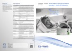
Figure 11: Schematic).
2.
Remove jumpers JP1, JP3, JP12, JP13, JP14 and JP15 to isolate the USB controller.
3.
Connect the SHDN_CHG pin (pin 2 of JP15) to VBUS (pin 2 of JP16) to enable the
charger operation (see Figure 11: Schematic).
The charger is now enabled and ready to be used in standalone mode.
If you connect the battery as mentioned in Section 2.2, then its presence is detected within a
few seconds and the charging operation starts.
Again as mentioned in Section 2.3, LED8 and LED9 are used to show the charging status.
14/21
UM0497
5
Warning/limitation
Warning/limitation
The limitations/warnings in using this evaluation board are as follows:
6
1.
The charging current is limited to 300 mA value using the USB supply. You can use an
external supply for increasing the charging current by using it in standalone mode as
mentioned in Section 4.
2.
There is no protection for reverse battery polarity connection, but it can be provided
according to customer requirements.
Reference
1.
AN2390: A Flexible Universal Battery Charger.
15/21
A
LED
D9
R20
100
5
6
R23
470
R27 1K
2STR1215
Q7
R32
OSC2_LITE
Y1
16MHZ
5
Q8
2STR1215
R38
10k
10k
R36
D7
1N5819
2STR2215
Q3
1
10k
R7
JP16
C17
100nF
1
2
10k
R42
1
RESET_LITE1BX
PA4(HS)/ATPWM2
PA2(HS)ATPWM0
PA0(HS)/LTIC
OSC2/PC1
PA6/MCO/ICCCLK/BREAK
2
10nF
R35
4k7
1
4
SW 2
2 RESET
COMPIN-/CLKIN/AIN4/PB4 PA7(HS)COMPOUT
MOSI/AIN3/PB3
2
1
9
10
11
12
13
14
15
16
0.5/1W (1%)
OSC1/CLKIN/PC0
C15
100nF
R26
I_AIN3
BT1
BATTERY
MISO/AIN2/PB2 PA5(HS)/ATPWM3/ICCDATA
SCK/AIN1/PB1
C22
1
1
2
C9
100nF
2
1
C7 2
100nF
VBUS
TP1
1
C23
200uF
ST1
ST2
JP1
USB_SUPPLY
2
4
6
8
10
3
OSC_IN
R41
100k
J7
CON3
OSCEXT_LITE
3
OSC1_LITE
VDD_LITE
R31
100k
2
1
1
3
5
7
9
CON10A
J8
10nF
SHDN_CHG
C19
RESET_ST7260 1
VDD_LITE
RESET
SW 1
2
2
100nF
C11
OUT
VSS
VCC
6
2
4
1
2
3
R3
18k
GND
LBI
REF
PA0/MCO
Vssa
USBDP
USBDM
33pF
C20
33pF
C16
2
OSCOUT
Y2
12MHZ
OSC_EXT
PA5/ICAP2/IT2
PA4/ICAP1/IT1
PA3/EXTCLK
13
1
Date:
Size
Title
CON1
J9
C8
100nF
R10
10k
R9
0
OPTIONAL
R4
0
OPTIONAL
USB_SUPPLY
500mA
J4
CON12
1
2
J5
CON3
8
1
3
5
2
R5
200k
CON1
CON1
J11
1
CON10A
J6
JP15
CON1
R33
10k
ICC_DATA
ICC_CLK
RESET_ST7260
VPP_7260
Monday, January 07, 2008
Document Number
USB BATTERY CHARGER _V1
1
Sheet
1
of
1
CON8
J2
Rev
1
R28
10k
VBUS
USBDM
VBUS_MON
2
SHDN_CHG
J12
2
4
6
8
10
2
JP12
JP3
1
2
3
4
5
6
7
8
IMS SYATEM LAB
1
1
3
5
7
9
1
1
ICC_CLK
1
2
USBDP
USBDM
1k5
ICC_DATA
R21
D4
LED
SHDN_CHG
VBUS_MON
USBDM
USBDP
2STR2215
ST2
Q2
ST1
R15
1k
VREG
USB_SUPPLY
C1
47uF/16V
47uF/16V
C2
1
USB BATTERY CHARGER
1
J10
USB_SUPPLY
OSC_EXT OSC_IN
PB0(10mA)
14
15
16
17
18
19
20
21
22
23
24
100nF
C10
PA7/OCMP2/IT4
USBOE/PB1(10mA)
PB2/10(mA)
PB3/(10mA)
Vpp/TEST
10k
VREG
R13
OUT
FB
LBO
SHDN
PA2(25mA)/SCL/ICCCLK
IT7/PB6(10mA)
RESET
L1
10uH
U2
L6920D
USBVcc
ST72F60E2M1
1
RDI/PC0PA1(25mA)/SDA/ICCDATA
TDO/PC1
VSS
OSCIN
OSCOUT
VDD
U4
1
1
2
2
U3
STM1061N25W X6F
R6 C5
16k 100nF
ICCDATA_LITE
ICCCLK_LITE
RESET_LITE1BX
12
R30
4k7
11
R39
10
2
JP14
1
4k7
9
VPP_7260
JP13
4k7 R40 1
2
8
7
6
5
4
2
1
OSCOUT
2
VREG
D2
1N5817
D1
1N5817
J3
CON12
R11
1k
M1
STT3PF30L
RESET_ST7260
1
USB_SUPPLY
VBUS
BATTOUT
ICCCLK_LITE
3
pwr select
Q9
2STR1215
ICCDATA_LITE
SW 2_PW M
SW 1_PW M
OSC2_LITE
OSC1_LITE
C14
100nF
3 PIN BATTERY
FOOTPRINT
1
2
VDD_LITE
ST7FLIT15BY0M6
COMPIN+SS/AIN0/PB0
RESET
VDD
VSS
VDD_LITE
8
7
6
ST2
T_AIN2
I_AIN3
5
4
3
2
1
U5
BATTOUT
TL1431AIZ
D5
5
6
7
8
R43
POT
SET
OUT
OUT
FAULT
100k
ST890BDR
GND
ON
IN
IN
R22
5k(0.5%)
4
3
2
1
U1
C13
R25
100nF 5k(0.5%)
2V_AIN1
R19
10k(0.1%)
V_AIN1
ST1
RESET_LITE1BX
VDD_LITE
2
50
DC TO DC
Q6
2STR1215
C12
470uF/16V
R16
R8
100k
R17
4k4(0.1%)
VBUS
1N5819
D6
D3
LED
R14
1k
C6
1uF/16V
2STR2215
Q1
VDD_LITE
R29
56
Q5
2STR1215
R24
82
VBUS
33uH
L2
100nF
C4
C3
4.7uF/25V
USB VDD
USBDM
USBDP
OSCEXT_LITE
1k R34
1kR34
1k
33pF
C21
33pF
C18
FOR 1A TRACK
LED D8
CON4
J1
1
2
3
4
SW 2_PW M
R18
330
R37
1M
VBUS
Q4
2STR1215
VBUS
B
C
D
100nF
C24
SW1_PWM
R2
1
3
2
T_AIN2
1
3
4
1
2
3
USB-B
1
2
3
4
5
6
7
8
9
10
11
12
7
LX
16/21
1
2
3
A
B
C
D
Appendix A
1
2
3
4
5
6
7
8
9
10
11
12
5
Schematic
UM0497
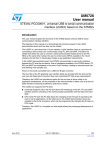
Schematic
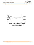
Figure 11. Schematic
UM0497
Schematic
6.1
USB battery charger BOM
Table 3.
Bill of materials
Index Qty Reference
Value/generic part
number
Package
Manufact.
Manufacturer’s
ordering code/
orderable part
number
1
2
C1,C2
47 µF/16 V
Electrolytic
cylindrical
Any
2
1
C3
4.7 µF/25 V
Electrolytic
cylindrical
Any
3
C4,C5,C7,
C8,C9,C1
0,C11,C1
12
3,C14,C1
5,C17,C2
4
100 nF
805
Any
4
1
C6
1 µF/16 V
Electrolytic
cylindrical
5
1
C12
470 µF/16 V
Electrolytic
cylindrical
Any
6
4
C16,C18,
C20,C21
33 pF
805
Any
7
2
C19,C22
10 nF
805
Any
8
1
C23
200 µF
Electrolytic
cylindrical
Any
9
2
D1,D2
1N5817
DO41
ST
10
4
D3,D4,D8,
D9
LED
Axial LED
Any
11
1
D5
TL1431AIZ
TO-92
ST
TL1431AIZ
12
2
D6,D7
1N5819
DO41
ST
1N5819
13
7
JP1,JP3,
JP12,
JP13,
JP14,
JP15,
JP16
Jumper
SIP-2
Any
14
1
J1
CON4
SIP-4
Any
15
1
J2
CON8
SIP-8
Any
16
2
J3,J4
CON12
SIP-12
Any
17
2
J5,J7
CON3
SIP-3
Any
18
2
J6,J8
CON10A
Box
header
Any
19
4
J9,J10,
J11, J12
CON1
Mounting
holes
Any
Suppl.
Supplier‘s
ordering
code
1N5817
17/21
Schematic
Table 3.
UM0497
Bill of materials (continued)
Index Qty Reference
Value/generic part
number
Package
Manufact.
Manufacturer’s
ordering code/
orderable part
number
20
1
L1
10 µH
Axial
inductor
Any
21
1
L2
33 µH
Axial
inductor
Any
22
1
M1
STT3PF30L
SOT23-6L
ST
STT3PF30L
23
3
Q1,Q2,Q3
2STR2215
SOT-23
ST
2STR2215
24
6
Q4,Q5,Q6
,Q7,Q8,
Q9
2STR1215
SOT-24
ST
2STR1215
25
4
R2,R8,
R31,R41
100 kΩ
805
Any
26
1
R3
18 kΩ
805
Any
27
2
R4,R9
0 (optional)
805
Any
28
1
R5
200 kΩ
805
Any
29
1
R6
16 kΩ
805
Any
30
8
R7,R10,
R13,R28,
R33,R36,
R38,R42
10 kΩ
805
Any
31
6
R11,R14,
R15,R27,
R32,R34
1 kΩ
805
Any
32
1
R16
50
805
Any
33
1
R17
4k4(0.1%)
805
RS
Components
34
1
R18
330
805
Any
35
1
R19
10 kΩ (0.1%)
805
RS
Components
36
1
R20
100
805
Any
37
1
R21
1k5
805
Any
38
2
R22,R25
5 kΩ (0.5%)
805
RS
Components
39
1
R23
470
805
Any
40
1
R24
82
805
Any
41
1
R26
0.5/1 W(1%)
RES Axial
Vishay
42
1
R29
56
805
Any
43
4
R30,R35,
R39,R40
4k7
805
Any
18/21
215-3112
215-3493
215-3162
CPF1R500000FL
Suppl.
Supplier‘s
ordering
code
UM0497
Table 3.
Schematic
Bill of materials (continued)
Index Qty Reference
Value/generic part
number
Package
Manufact.
Manufacturer’s
ordering code/
orderable part
number
44
1
R37
1M
805
Any
45
1
R43
POT
Top notch
3296
Any
46
2
SW1,SW2
Reset
Push
button
Any
47
1
TP1
Test point
Single
berg pin
Any
48
1
U1
ST890BDR
SO-8
ST
ST890BDR
49
1
U2
L6920D
TSSOP8
ST
L6920D
50
1
U3
STM1061N25WX6F
SOT23-3
ST
STM1061N25WX6F
51
1
U4
ST72F60E2M1
SO24
ST
ST72F60E2M1
52
1
U5
ST7FLIT15BY0M6
SO16
ST
ST7FLIT15BY0M6
53
1
Y1
16 MHz
Crystal
oscillator
Any
54
1
Y2
12 MHz
Crystal
oscillator
Any
Suppl.
Supplier‘s
ordering
code
19/21
Revision history
7
UM0497
Revision history
Table 4.
20/21
Document revision history
Date
Revision
07-Feb-2008
1
Changes
Initial release
UM0497
Please Read Carefully:
Information in this document is provided solely in connection with ST products. STMicroelectronics NV and its subsidiaries (“ST”) reserve the
right to make changes, corrections, modifications or improvements, to this document, and the products and services described herein at any
time, without notice.
All ST products are sold pursuant to ST’s terms and conditions of sale.
Purchasers are solely responsible for the choice, selection and use of the ST products and services described herein, and ST assumes no
liability whatsoever relating to the choice, selection or use of the ST products and services described herein.
No license, express or implied, by estoppel or otherwise, to any intellectual property rights is granted under this document. If any part of this
document refers to any third party products or services it shall not be deemed a license grant by ST for the use of such third party products
or services, or any intellectual property contained therein or considered as a warranty covering the use in any manner whatsoever of such
third party products or services or any intellectual property contained therein.
UNLESS OTHERWISE SET FORTH IN ST’S TERMS AND CONDITIONS OF SALE ST DISCLAIMS ANY EXPRESS OR IMPLIED
WARRANTY WITH RESPECT TO THE USE AND/OR SALE OF ST PRODUCTS INCLUDING WITHOUT LIMITATION IMPLIED
WARRANTIES OF MERCHANTABILITY, FITNESS FOR A PARTICULAR PURPOSE (AND THEIR EQUIVALENTS UNDER THE LAWS
OF ANY JURISDICTION), OR INFRINGEMENT OF ANY PATENT, COPYRIGHT OR OTHER INTELLECTUAL PROPERTY RIGHT.
UNLESS EXPRESSLY APPROVED IN WRITING BY AN AUTHORIZED ST REPRESENTATIVE, ST PRODUCTS ARE NOT
RECOMMENDED, AUTHORIZED OR WARRANTED FOR USE IN MILITARY, AIR CRAFT, SPACE, LIFE SAVING, OR LIFE SUSTAINING
APPLICATIONS, NOR IN PRODUCTS OR SYSTEMS WHERE FAILURE OR MALFUNCTION MAY RESULT IN PERSONAL INJURY,
DEATH, OR SEVERE PROPERTY OR ENVIRONMENTAL DAMAGE. ST PRODUCTS WHICH ARE NOT SPECIFIED AS "AUTOMOTIVE
GRADE" MAY ONLY BE USED IN AUTOMOTIVE APPLICATIONS AT USER’S OWN RISK.
Resale of ST products with provisions different from the statements and/or technical features set forth in this document shall immediately void
any warranty granted by ST for the ST product or service described herein and shall not create or extend in any manner whatsoever, any
liability of ST.
ST and the ST logo are trademarks or registered trademarks of ST in various countries.
Information in this document supersedes and replaces all information previously supplied.
The ST logo is a registered trademark of STMicroelectronics. All other names are the property of their respective owners.
© 2008 STMicroelectronics - All rights reserved
STMicroelectronics group of companies
Australia - Belgium - Brazil - Canada - China - Czech Republic - Finland - France - Germany - Hong Kong - India - Israel - Italy - Japan Malaysia - Malta - Morocco - Singapore - Spain - Sweden - Switzerland - United Kingdom - United States of America
www.st.com
21/21