1
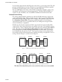
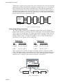
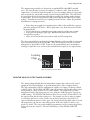
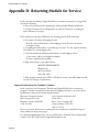
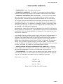
SCADA 3000 User’s Manual
Termination is required at the extreme ends of the communications network to minimize
signal reflections that would otherwise cause data communication errors. To activate the
Bus Termination, move the jumper to the IN position. Note that this should only be
activated if the module is at the very end of the network. All other modules in between
should have the termination set to the OUT position. As a result, only 1 module (plus
the main unit) should ever have the termination activated. The diagram below illustrates
proper termination of the communications bus.
Main
Unit
Out
In
Out
Out
In
Figure 7: Correct bus termination
Analog Output Wiring Information
The analog output module has four independent outputs which can be configured to
produce either 4-20mA, 0-20mA or 0-10V. The output type is selected using the jumpers
(J8-J11) above the terminal strip. The output types must be set in pairs. Jumper pair one
affects outputs 0 and 1, and pair two affects outputs 2 and 3. This allows you to set, for
example, outputs 0 and 1 to 4-20mA, and outputs 2 and 3 to 0-10V. The table below
shows how to set the jumpers for each output type.
Outputs 0 & 1
Outputs 2 & 3
Type
Jumper Settings
Type
Jumper Settings
4-20mA
J8: 4-20, J10: mA
4-20mA
J9: 4-20, J11: mA
0-20mA
J8: 0-20, J10: mA
0-20mA
J9: 0-20, J11: mA
0-10V
J8: 0-20, J10: V
0-10V
J9: 0-20, J11: V
When configured for 4-20mA or 0-20mA, each output can drive a maximum of 1000
Ohms. The output current is sourced directly from the module. No external loop power
is required. When configured for 0-10V, be sure to drive only high impedance loads to
minimize errors. A typical circuit connection diagram is shown below.
J8
J10
J9
+
+
OUTPUT
DEVICE
J11
0-20
4-20
0-20
4-20
0
—
+
—
1
+
+
—
2
+
3
—
OUTPUT
DEVICE
Figure 8: Wiring diagram
AOM-10
+
OUTPUT
DEVICE