1
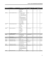
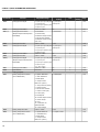
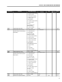
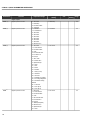
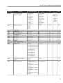
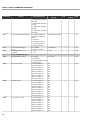
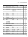
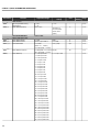
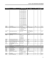
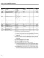
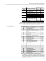
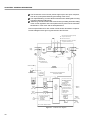
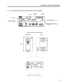
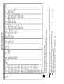
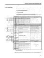
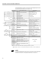
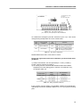
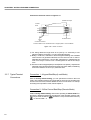
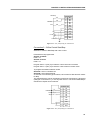
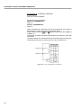
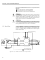
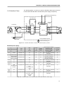
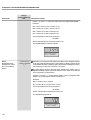
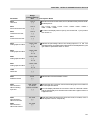
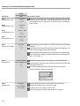
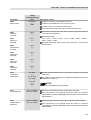
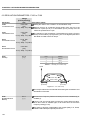
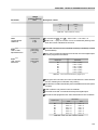
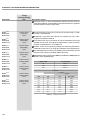
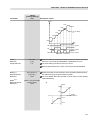
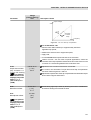
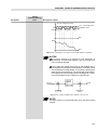
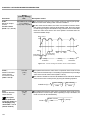
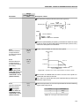
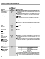
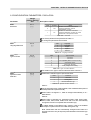
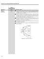
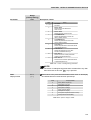
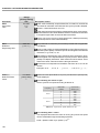
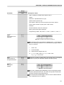
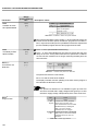
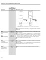
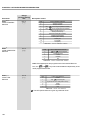
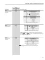
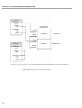
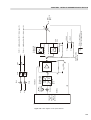
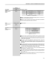
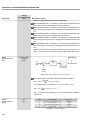
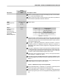
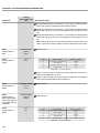
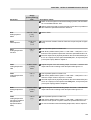
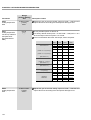
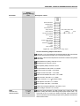
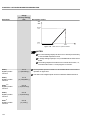
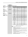
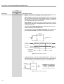
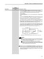
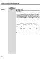
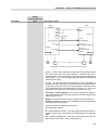
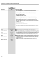
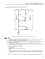
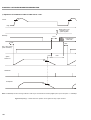
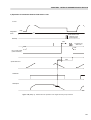
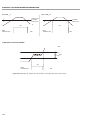
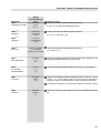
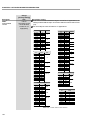
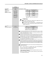
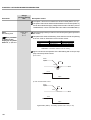
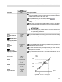
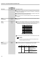
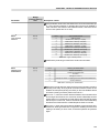
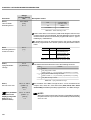
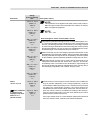
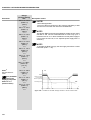
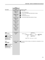
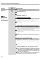
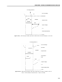
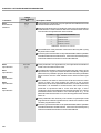
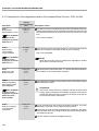
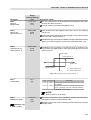
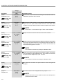
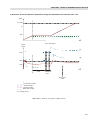
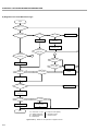
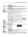
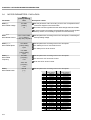
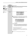
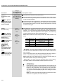
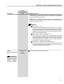
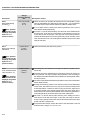
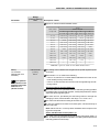
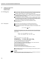
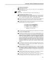
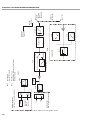
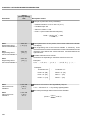
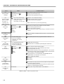
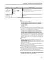
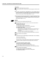
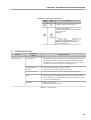
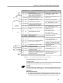
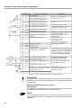
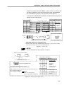
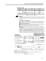
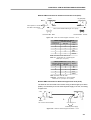
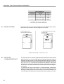
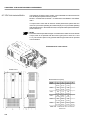
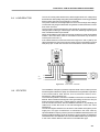
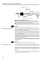
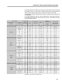
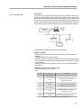
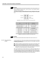
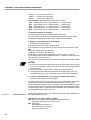
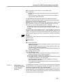
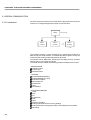
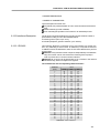
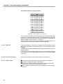
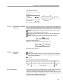
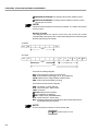
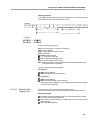
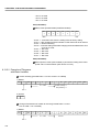
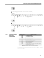
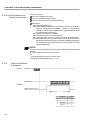
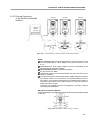
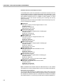
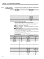
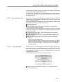
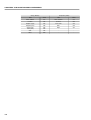
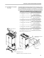
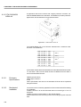
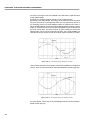
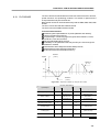
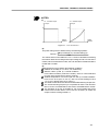
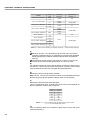
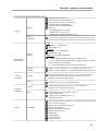
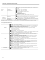
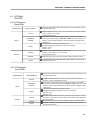
CHAPTER 8 - CFW-09 OPTIONS AND ACCESSORIES At start-up, program Parameter P202 – Type of Control = 4 (Vector with Encoder) to operate the motor with incremental encoder speed feedback. For more details about Vector Control operation refer to chapter 5. The Expanded I/O Boards EBA and EBB are provided with externally powered, isolated encoder output signals. Connector XC9 Encoder Connector*** A A H A B B I B C Z J Z D +VE F COM E NC red blue yellow green grey pink white brown Descripition 3 A 2 A 1 B 9 B 8 Z 7 4 Z +VE Power Supply* 6 COM 0 V Reference** Encoder Signals 12 V differential (88C20) 5 Ground cable shield G CFW-09 EBA or EBB Board Encoder Max. Recommended lenght: 100 m (300 ft) Connector XC9 (DB9 - Male) * Power supply voltage 12 Vdc / 220 mA for encoder. ** Referenced to ground via 1 F in parallel with 1 k *** Valid pin position with encoder HS35B models from Dynapar. For other encoder modules, check the correct connection to meet the required sequence. Figure 8.7 – Encoder cable NOTE! The max. permitted encoder frequency is 100 kHz. Sequence of the encoder signals: B t CFW-09 EBA or EBB Board A t Motor running clockwise. 5 1 Connector XC8 (DB9 Female) 9 6 *For on external power supply: 5 V to 15 V Consumption: 100 mA @ 5 V, outputs not included. Note: Optionally, the external power supply can also be connected via: XC4:19 and XC4:20 (EBA) or XC5:19 and XC5:20 (EBB) NOTE! There is no internal power supply for XC8 at EBA or EBB board. Connector XC8 Descrition Encoder Signals 3 A 2 A 1 B 9 B 8 Z 7 Z 4 +V* Power Supply* 6 COM 1* 0 V Refrence 5 Line Driver differential (88C30) Average high level current: 50 mA Ground Figure 8.8 – Encoder signals repeater output 255