1
CHAPTER 8 - CFW-09 OPTIONS AND ACCESSORIES
8.19
PLC BOARD
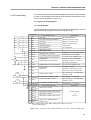
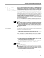
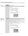
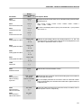
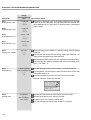
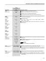
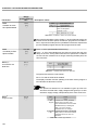
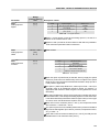
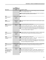
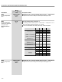
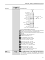
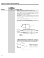
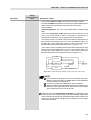
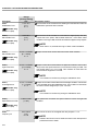
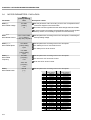
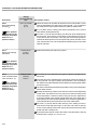
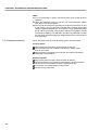
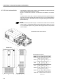
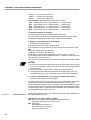
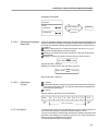
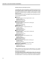
The PLC1 and PLC2 boards allow the CFW-09 inverter to have PLC function,
speed reference and positioning modules. This board is optional and is
incorporated internally into the CFW-09.
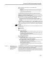
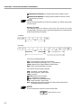
Both boards cannot be used simultaneously with the EBA, EBB, EBC, EBE
boards.
The PLC1 cannot be used with Fieldbus boards.
The PLC2 can have Fieldbus board mounted.
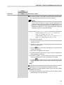
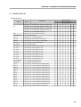
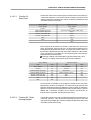
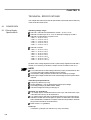
Technical Characteristics
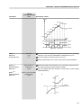
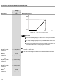
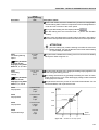
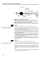
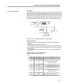
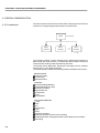
Positioning with trapezoidal and “S” profile (absolute and relative);
Homing (machine zero search);
Programming in Ladder language through the WLP Software, Timers,
Contactors, Coils and Contacts;
RS-232 with Modbus RTU protocol;
Availability of 100 parameters that may be set by the user through the
Software or via HMI;
CAN interface with CANopen and DeviceNet protocols;
Master/Slave function (ElectronicGear Box);
It has own 32 bits CPU with flash memory.
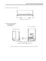
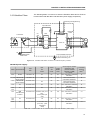
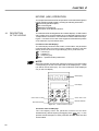
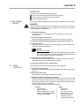
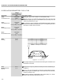
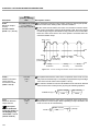
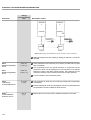
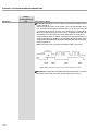
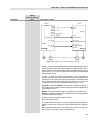
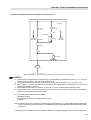
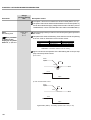
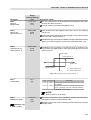
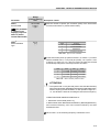
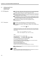
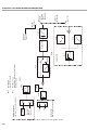
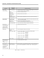
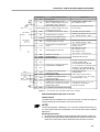
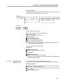
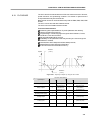
Position 1
(t0 to t2)
Speed
Position 3
(t5 - t12)
V1
V3
t2
t3
t4
Time
t5
t1
t6
t7
t8
t9
t10
t11
t12
V2
Position 2
(t2 to t5)
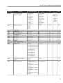
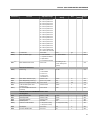
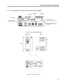
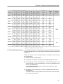
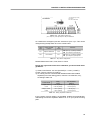
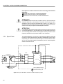
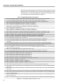
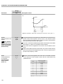
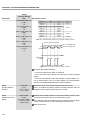
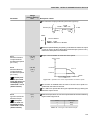
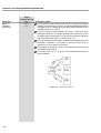
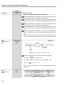
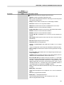
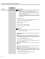
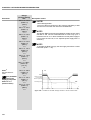
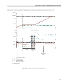
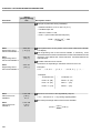
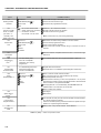
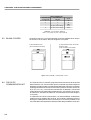
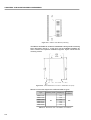
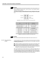
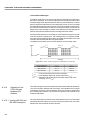
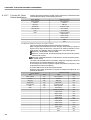
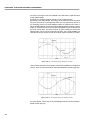
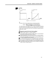
Figure 8.60 - Trajectory example by using the PLC board
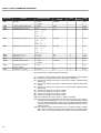
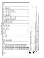
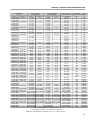
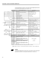
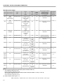
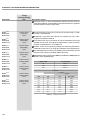
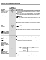
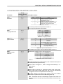
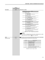
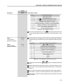
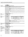
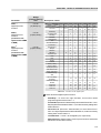
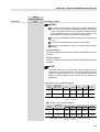
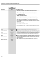
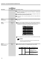
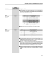
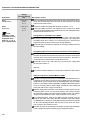
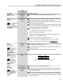
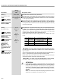
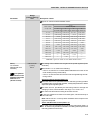
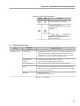
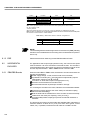
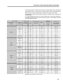
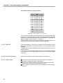
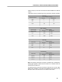
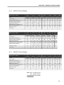
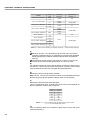
Input/Output
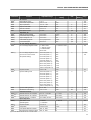
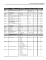
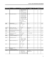
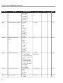
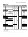
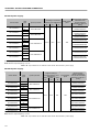
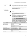
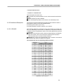
Technical Specification
PLC 1
Quantities
Description
Quantities
24 Vdc bipolar
24 Vdc bipolar
Digital inputs
9
Relay outputs
3
Transistorized outputs
3
Encoder power supply
1
Analog output
-
-
2
12 bits (-10 V to +10 V or
(0 to 20) mA)
Analog input
-
-
1
14 bits (-10 V to +10 V or
(-20 to 20) mA)
-
-
1
Motor PTC isolated input
250 Vac/3 A ou
250 Vdc/3 A
24 Vdc/500 mA
15 V
9
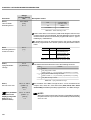
PLC 2
Description
3
3
2
250 Vac/3 A or
250 Vdc/3 A
24 Vdc/500 mA
5 to 24 V
Motor PTC isolated input
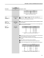
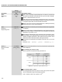
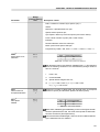
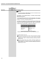
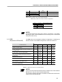
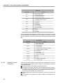
Note: For more details, refer to the PLC Board Manual. The manual is available in the site: www.weg.net.
335