1
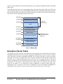
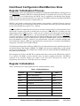
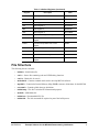
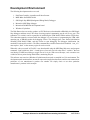
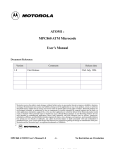
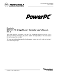
05/98
™
Application Note
Example Software for the MPC860
Demonstrating Initialization
Netcomm Applications
Motorola, Austin, Texas
This document explains one approach to initializing the MPC860. It is designed to explain
the process of how software begins execution from a power-up condition. It also includes
the start of a debug port utilizing SMC2. It is important to note that this document is written
from a software engineer’s point of view, so the hardware reset process, when mentioned,
is discussed only to clarify the software initialization process. One common configuration
was chosen for this example. It is left up to the reader to apply this example to a particular
design. Most of the technical details are described in the form of in-line documentation
embedded in the initialization source file. This document will only provide a high-level
overview with more discussion in some areas that need further clarification.
With this initialization example, a developer can integrate one of the available CPM-related
software examples to form a starting platform. Integrating these software components and
using them in conjuction with Motorola’s MPC860 ADS hardware testing platform will
allow a software developer to begin the development phase before actual target hardware
is available.
The PowerPC name, and the PowerPC logotype are trademarks of International Business Machines Corporation, used by Motorola under license from
International Business Machines Corporation.
This document contains information on a new product under development by Motorola and IBM. Motorola and IBM reserve the right to change or
discontinue this product without notice.
© Motorola Inc., 1998. All rights reserved.
Example Software for MPC860
Initialization Application Note
Introduction
Software Overview
The areas requiring initialization on the MPC860 are as follows:
•
PowerPC core registers
•
Memory Management Unit (MMU)
•
Instruction and Data Cache
•
Clock circuitry
•
System PLL (SPLL)
•
Timers and Counters
•
System Interface Unit (SIU)
•
User Program Machines (UPMA)
•
Chip Select Machine
•
UPM Tables
•
Baud Rate Generator 2
•
SMC2
No programming order is implied here. To learn the approach taken in this example, refer to the included
source code.
This software was designed to work with the MPC860 ADS board and functions similar to Motorola’s
MPC8BUG debugger software initialization. The PowerPC core system clock, as well as the external bus
frequency was chosen to be 24 MHz. This clock is derived from a 4 MHz crystal oscillator fed to the
EXTCLK pin of the MPC860. The Hard Reset Configuration Word as well as MODCK1 and MODCK2 are
defined by the BCSRs (Board Control and Status Registers located on the target) and is read on reset.
SMC2 was initialized to perform echo capability to Port B (PB3), the RS232 port. This means an ASCII
terminal can be connected and characters typed will be returned to the terminal at 9600 baud. The reasons
for this function are two-fold. A way was needed to test the success of initialization, and it’s a useful function
for a developer who wants to develop a debug port. The Ethernet LED on the 860ADS board blinks to give
a simple visual indication that initialization was complete and code is executing in the main loop.
References
It is important that users familiarize themselves with the following references for a better understanding of
the terminology and general MPC860 programming model.
•
MPC860 PowerQUICC™ User’s Manual; MPC860UM/AD
•
PowerPC™ Microprocessor Family: The Programming Environments for 32-Bit Microprocessors;
MPCFPE32B/AD, Rev. 1
Memory Map Definition
The memory map established during initialization is shown in Figure 1. This memory map includes areas
for 4 Mbytes of DRAM, 16 Kbytes of BCSR (Board Control and Status Registers) space, 32 Kbytes for
internal memory map registers/dual-port RAM, and 2 Mbytes (512K x 32) of FLASH memory.
Chip Select 0 (CS0) is configured for Flash memory, CS1 for Board Control Status Registers (BCSR) and
CS2 is used for DRAM. Bank Register 0 (BR0) and Option Register 0 (OR0) are used to define the address
2
Example Software for the MPC860 Demonstrating Initialization
MOTOROLA
space for the Flash. BR1/OR1 contain the BCSR address space definitions and BR2/OR2 define the DRAM
address space.
The BCSRs discussed above are 4 programmable logic parts that reside on the ADS board. The Board
Control and Status Registers consist of the BCSR0, BCSR1, BCSR2, and BCSR3 and descriptions of these
parts and their functions can be found in the MPC860 ADS manual included with the MPC860 ADS board.
They provide special configurability options for the ADS.
0x00000000
EXCEPTION VECTOR TABLE
0x00002000
PROGRAM STACK AND DATA
4 MBYTE
DRAM SPACE
0x00002800
DRAM
0x003FFFFF
EMPTY SPACE
0x02100000
0x02104000
BCSR (BOARD CONTROL
AND STATUS REGISTER
EMPTY SPACE
0x02800000
FLASH (512K X 32) BYTES
Initialization code is
located at the start of
flash space
0x02A00000
0xFF000000
EMPTY SPACE
INTERNAL REGISTERS
DUAL-PORT RAM
0xFF004000
0xFFFFFFFF
EMPTY SPACE
Figure 1. Memory Map
Exception Vector Table
The original copy of the exception vector table exists at the beginning of the initialization code located at
0x02800000 in the flash after CS0 is initialized. During the initialization process, the exception vector table
will be physically re-located to 0x00000000 in DRAM. The exception vector table is set up as an indirect
jump table for PowerPC exceptions. Most of the exceptions are defined in this example; debug related
exceptions were not. When the MPC860 comes out of reset, CS0 is the global chip select. CS0 is tied
directly to the flash bank. The instruction pointer’s (IP) initial value is 0x00000100 because of the Hard
Reset Word “IP” value which is read from the data bus. Because CS0 is tied directly to the flash, and it
asserts on any address in a 0-4 gbit memory region, 0x00000100 is accessed in flash. Again, once
initialization code is vectored to, CS0 will be re-initialized to assert from addresses 0x02800000 to
0x02A00000 in this example. The next section describes the initial reset process in more detail.
MOTOROLA
Example Software for the MPC860 Demonstrating Initialization
3
Hard Reset Configuration Word/Machine State
Register Initialization Process
The first register value to get established is the Hard Reset Configuration Word (HRCW). During power-on
reset, RSTCONF determines if HRCW is read from the data bus or if a default value of 0 is used. The second
register that needs to be initialized after the HRCW value is established is the Machine State Register
(MSR). This register is part of the PowerPC core register set. The MSR contains bits that define fundamental
system functions. On power-up reset it’s default value is 0.
HRCW is only loaded at certain times. In this example, power-up reset is described. However, power-up
reset isn’t the only type of reset that causes HRCW to be re-loaded. These other types are listed in the reset
section of the MPC860 PowerQUICC User’s Manual.
The IP bit in HRCW is important to the reset process in terms of software flow. It’s value determines where
the PowerPC exception vector table is located when a reset occurs. If IP in HRCW is 0 (default), the value
transparently written to MSRip bit 25 is 1. In this case, the exception vector table needs to start at physical
address 0xFFFn_nnnn. If IP in HRCW is 1, the value transparently written to the MSRip bit 25 is 0 and the
exception vector table is assumed to start at physical address 0x000n_nnnn. In this example, RSTCONF is
asserted so the data bus is read. The HRCW value is provided by BCSR0 and the value driven on the data
bus is 0x41600000. For HRCWip, whose bit is set, means that the vector table is located at 0x000n_nnnn.
Once initialization software starts to run, the initialization code relocates the vector table to 0x00000000 by
copying the vector table from FLASH to DRAM.
The Initial Internal Space Base (ISB) bits in HRCW are also important because they determine the value of
the Internal Memory Map Register (IMMR). The IMMR value gives the starting address of the internal
memory map registers space. This example chose an ISB value of 10 which establishes the IMMR physical
base address at 0xFF000000.
Full descriptions of all bits in the HRCW are explained in the Reset section of the MPC860 PowerQUICC
User’s Manual. The MSR is accessed with the mtmsr and mfmsr assembly mnemonics. The MSR is
explained in the PowerPC Register Set chapter of the PowerPC™ Microprocessor Family: The
Programming Environments for 32-Bit Microprocessors Manual.
Register Initialization
Table 1 contains the list of most registers that were initialized and their values:
Table 1. Initialized Registers
Register
4
Description
Value
MSR
Machine State Register
0x1002
SRR1
Status Save/Restore Register
0x1002
HRCW
Hard Reset Configuration Word
0x4160
LR
Link Register
Current IP value
IMMR
Internal Memory Map Register
0xFF000000
SYPCR
System Protection Control Register
0xFFFFFF88
MPTPR
Memory Periodic Timer Prescaler Register
0x0800
MAMR
Machine A Mode Register
0xBBA21114
Example Software for the MPC860 Demonstrating Initialization
MOTOROLA
Table 1. Initialized Registers (Continued)
Register
Description
Value
BR0
Base Register 0
0x02800001
OR0
Option Register 0
0xFFFE0954
BR1
Base Register 1
0x02100001
OR1
Option Register 1
0xFFFF8110
BR2
Base Register 2
0x00000081
OR2
Option Register 2
0xFFC00800
SIUMCR
SIU Module Configuration Register
0x00032640
TBSCR
Timebase Control and Status
Register
0x0000
PISCR
Periodic Interrupt Status and Control
Register
0x0082
ICTRL
Instruction Support Control Register
0x00000006
DER
Debug Enable Register
0x00000000
SCCR
System Clock Control Register
0x01800000
PLPRCR
PLL, Low Power, and Reset Control
Register
0x00500000
File Structure
The following files are included:
•
init860.s—Initialization file
•
smc2.c—Source file containing echo and LED flashing functions
•
smc2.h—Header file for smc2.c
•
masks860.h—Contains standard masks used to develop MPC860 software
•
mpc860.h—Contains the Internal Memory Map (IMMR) structure declarations for the MPC860
•
netcomm.h—Contains global data type definitions
•
init860.map—This file is included for informational purposes
•
makefile—MKS Make file
•
init860.out—Downloadable ELF file
•
init860.lnk—The link command file required as part of the build process
MOTOROLA
Example Software for the MPC860 Demonstrating Initialization
5
Development Environment
The following development tools were used:
1. Diab Data Compiler, Assembler and Linker/Locator
2. MKS Make from MKS Toolkit
3. SDS Single Step BDM (Background Debug Mode) Debugger
4. Motorola’s MPC8Bug debugger
5. Motorola ADS MPC860 development board
6. Windows 95 platform
The Diab Data toolset was used to produce an ELF file that was downloaded to DRAM by the SDS Single
Step debugger and then tested. This form of testing required commenting out the call to init_upm. This
subroutine is in init860.s and is responsible for initializing the UPM RAM, UPMA and the Chip Selects.
This subroutine cannot be executed while the debugger is in use because re-programming the UPM while
operating out of DRAM crashes the debugging session. The debugger does some limited initialization
including UPM RAM, UPMA, and chip selects to start debugging. The debugger initialization just
mentioned is mirrored in init860.s. The linker command file init860.lnk must also be modified. “ram_rest”
must replace “flash” as the memory region for code to reside.
When this code was tested in FLASH, it was downloaded using the MPC8Bug flash erase and program
command “loadf init860.out 3000”. A small piece of test code was left at the end of “init860.s” that was
used during FLASH based debug to toggle Port A bit 0 pin. With an oscilloscope, code execution was
verified at various points during initialization, monitoring this pin.
This software was tested on a Windows 95 platform and not tested or compiled in a Unix environment. The
development tools mentioned here are not an expressed or implied endorsement, and does not communicate
preference of one manufacturer’s product over another. We simply chose to use these particular
manufacturer’s products in this example.
6
Example Software for the MPC860 Demonstrating Initialization
MOTOROLA
Information in this document is provided solely to enable system and software implementers to use PowerPC microprocessors. There are no express or implied
copyright licenses granted hereunder to design or fabricate PowerPC integrated circuits or integrated circuits based on the information in this document.
Motorola reserves the right to make changes without further notice to any products herein. Motorola makes no warranty, representation or guarantee
regarding the suitability of its products for any particular purpose, nor does Motorola assume any liability arising out of the application or use of any product or
circuit, and specifically disclaims any and all liability, including without limitation consequential or incidental damages. “Typical” parameters can and do vary in
different applications. All operating parameters, including “Typicals” must be validated for each customer application by customer’s technical experts. Motorola
does not convey any license under its patent rights nor the rights of others. Motorola products are not designed, intended, or authorized for use as components
in systems intended for surgical implant into the body, or other applications intended to support or sustain life, or for any other application in which the failure
of the Motorola product could create a situation where personal injury or death may occur. Should Buyer purchase or use Motorola products for any such
unintended or unauthorized application, Buyer shall indemnify and hold Motorola and its officers, employees, subsidiaries, affiliates, and distributors harmless
against all claims, costs, damages, and expenses, and reasonable attorney fees arising out of, directly or indirectly, any claim of personal injury or death
associated with such unintended or unauthorized use, even if such claim alleges that Motorola was negligent regarding the design or manufacture of the part.
Motorola and
are registered trademarks and PowerQUICC is a trademark of Motorola, Inc. Mfax is a trademark of Motorola, Inc. Motorola, Inc. is an Equal
Opportunity/Affirmative Action Employer.
The PowerPC name and the PowerPC logotype are trademarks of International Business Machines Corporation used by Motorola under license from
International Business Machines Corporation.
Motorola Literature Distribution Centers:
USA/EUROPE: Motorola Literature Distribution; P.O. Box 5405; Denver, Colorado 80217; Tel.: 1-800-441-2447 or 1-303-675-2140;
World Wide Web Address: http://ldc.nmd.com/
JAPAN: Nippon Motorola Ltd SPD, Strategic Planning Office 4-32-1, Nishi-Gotanda Shinagawa-ku, Tokyo 141, Japan Tel.: 81-3-5487-8488
ASIA/PACIFC: Motorola Semiconductors H.K. Ltd.; 8B Tai Ping Industrial Park, 51 Ting Kok Road, Tai Po, N.T., Hong Kong; Tel.: 852-26629298
Mfax™: [email protected]; TOUCHTONE 1-602-244-6609; US & Canada ONLY (800) 774-1848;
World Wide Web Address: http://sps.motorola.com/mfax
INTERNET: http://motorola.com/sps
Technical Information: Motorola Inc. SPS Customer Support Center; 1-800-521-6274; electronic mail address: [email protected].
Document Comments: FAX (512) 895-2638, Attn: RISC Applications Engineering.
World Wide Web Addresses: http://www.mot.com/SPS/PowerPC/
http://www.mot.com/SPS/RISC/netcomm/