1
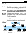
DirectSOFT
Quick Start
Manual Number QS--DSOFT-M
WARNING
Thank you for purchasing automation equipment from PLCDirectä. We want your new DirectLOGICä automation
equipment to operate safely. Anyone who installs or uses this equipment should read this publication (and any other
relevant publications) before installing or operating the equipment.
To minimize the risk of potential safety problems, you should follow all applicable local and national codes that regulate
the installation and operation of your equipment. These codes vary from area to area and usually change with time. It is
your responsibility to determine which codes should be followed, and to verify that the equipment, installation, and
operation is in compliance with the latest revision of these codes.
At a minimum, you should follow all applicable sections of the National Fire Code, National Electrical Code, and the
codes of the National Electrical Manufacturer’s Association (NEMA). There may be local regulatory or government
offices that can also help determine which codes and standards are necessary for safe installation and operation.
Equipment damage or serious injury to personnel can result from the failure to follow all applicable codes and
standards. We do not guarantee the products described in this publication are suitable for your particular application,
nor do we assume any responsibility for your product design, installation, or operation.
If you have any questions concerning the installation or operation of this equipment, or if you need additional
information, please call us at 1--800--633--0405.
This publication is based on information that was available at the time it was printed. At PLCDirectä we constantly
strive to improve our products and services, so we reserve the right to make changes to the products and/or
publications at any time without notice and without any obligation. This publication may also discuss features that may
not be available in certain revisions of the product.
Trademarks
This publication may contain references to products produced and/or offered by other companies. The product and
company names may be trademarked and are the sole property of their respective owners. PLCDirectä disclaims any
proprietary interest in the marks and names of others.
Stage is a trademark of Koyo Electronics Industries Co., LTD. Texas Instruments is a registered trademark of Texas
Instruments, Inc. TI, TIWAY, Series 305, Series 405, TI305, and TI405 are trademarks of Texas Instruments, Inc.
Siemens and SIMATIC are registered trademarks of Siemens, AG. GE is a registered trademark of General Electric
Corporation. Series One is a registered trademark of GE Fanuc Automation North America, Inc. MODBUS is a
registered trademark of Gould, Inc. IBM is a registered trademark of International Business Machines. MS-DOS and
Microsoft are registered trademarks of Microsoft Corporation. Windows is a trademark of Microsoft Corporation.
OPTOMUX and PAMUX are trademarks of OPTO 22.
Copyright 1997, PLCDirectä Incorporated
All Rights Reserved
No part of this manual shall be copied, reproduced, or transmitted in any way without the prior, written consent of
PLCDirectä Incorporated. PLCDirectä retains the exclusive rights to all information included in this document.
1
Manual Revisions
If you contact us in reference to this manual, remember to include the revision number.
Title: DirectSOFT Quick Start User Manual
Manual Number: QS--DSOFT--M
Issue
Date
Effective Pages
Description of Changes
Original
9/96
Cover/Copyright
Contents
Manual Revisions
1 — 57
Original Issue
2nd Edition
2/97
Contents
Manual Revisions
1 — 56
Down size format
3rd Edition
6/98
Contents
Manual Revisions
1 — 56
Add D3--350
Release 2.3 (3 diskettes)
1
Table of Contents
i
Introduction . . . . . . . . . . . . . . . . . . . . . . . . . . . . . . . . . . . . . . . . . . . . . . . . . . . . . . . . . . . . . . . . . . . . . . . .
The Purpose of this Supplementary Manual . . . . . . . . . . . . . . . . . . . . . . . . . . . . . . . . . . . . . . . . . . .
Make Backup Copies of Your Diskettes . . . . . . . . . . . . . . . . . . . . . . . . . . . . . . . . . . . . . . . . . . . . . .
Who Can and Should Use DirectSOFT? . . . . . . . . . . . . . . . . . . . . . . . . . . . . . . . . . . . . . . . . . . . . . .
PLC Compatibility . . . . . . . . . . . . . . . . . . . . . . . . . . . . . . . . . . . . . . . . . . . . . . . . . . . . . . . . . . . . . . . . .
1
1
1
1
2
Installing the Software . . . . . . . . . . . . . . . . . . . . . . . . . . . . . . . . . . . . . . . . . . . . . . . . . . . . . . . . . . . . . . .
Step1: Start Windows . . . . . . . . . . . . . . . . . . . . . . . . . . . . . . . . . . . . . . . . . . . . . . . . . . . . . . . . . . . . . .
Step 2: Load the Setup Program from your Disks . . . . . . . . . . . . . . . . . . . . . . . . . . . . . . . . . . . . . .
Step 3: Complete the Registration Information . . . . . . . . . . . . . . . . . . . . . . . . . . . . . . . . . . . . . . . .
Step 4: Select the Installation Options . . . . . . . . . . . . . . . . . . . . . . . . . . . . . . . . . . . . . . . . . . . . . . . .
The Installation Process . . . . . . . . . . . . . . . . . . . . . . . . . . . . . . . . . . . . . . . . . . . . . . . . . . . . . . . . . . . .
3
3
3
4
4
5
Building an Example Program . . . . . . . . . . . . . . . . . . . . . . . . . . . . . . . . . . . . . . . . . . . . . . . . . . . . . . . .
What You Will Learn . . . . . . . . . . . . . . . . . . . . . . . . . . . . . . . . . . . . . . . . . . . . . . . . . . . . . . . . . . . . . . .
A Simple Example . . . . . . . . . . . . . . . . . . . . . . . . . . . . . . . . . . . . . . . . . . . . . . . . . . . . . . . . . . . . . . . . .
Sample Ladder Logic . . . . . . . . . . . . . . . . . . . . . . . . . . . . . . . . . . . . . . . . . . . . . . . . . . . . . . . . . . . . . .
Step 1: Enter the Programming Mode . . . . . . . . . . . . . . . . . . . . . . . . . . . . . . . . . . . . . . . . . . . . . . . .
Step 2: Start a New Project . . . . . . . . . . . . . . . . . . . . . . . . . . . . . . . . . . . . . . . . . . . . . . . . . . . . . . . . .
Step 3: Switch to the Edit Mode . . . . . . . . . . . . . . . . . . . . . . . . . . . . . . . . . . . . . . . . . . . . . . . . . . . . .
The Tool Palette . . . . . . . . . . . . . . . . . . . . . . . . . . . . . . . . . . . . . . . . . . . . . . . . . . . . . . . . . . . . . . . . . . .
Step 4: Using the Tool Palette to Enter the First Element . . . . . . . . . . . . . . . . . . . . . . . . . . . . . . .
Step 5: Using the SP0 Relay in Our Program. . . . . . . . . . . . . . . . . . . . . . . . . . . . . . . . . . . . . . . . . .
Step 6: Using the Box Browser . . . . . . . . . . . . . . . . . . . . . . . . . . . . . . . . . . . . . . . . . . . . . . . . . . . . . .
Step 7: Scrolling the Box Class Window . . . . . . . . . . . . . . . . . . . . . . . . . . . . . . . . . . . . . . . . . . . . . .
Step 8: Entering a Preset in the Accumulator . . . . . . . . . . . . . . . . . . . . . . . . . . . . . . . . . . . . . . . . .
Step 9: Connecting Elements in Parallel . . . . . . . . . . . . . . . . . . . . . . . . . . . . . . . . . . . . . . . . . . . . . .
Step 10: Inserting an Output Box . . . . . . . . . . . . . . . . . . . . . . . . . . . . . . . . . . . . . . . . . . . . . . . . . . . .
Step 11: Entering the Address to Hold the Preset . . . . . . . . . . . . . . . . . . . . . . . . . . . . . . . . . . . . . .
Step 12: Enabling the Documentation Options . . . . . . . . . . . . . . . . . . . . . . . . . . . . . . . . . . . . . . . .
Step 13: Entering a Comment . . . . . . . . . . . . . . . . . . . . . . . . . . . . . . . . . . . . . . . . . . . . . . . . . . . . . . .
Step 14: Assigning a Nickname to the Preset Output . . . . . . . . . . . . . . . . . . . . . . . . . . . . . . . . . . .
Step 15: Adding an Internal Relay to Start the Timer . . . . . . . . . . . . . . . . . . . . . . . . . . . . . . . . . . .
Step 16: Assigning a Nickname to the Start Contact . . . . . . . . . . . . . . . . . . . . . . . . . . . . . . . . . . .
Step 17: Adding a Normally Closed Contact . . . . . . . . . . . . . . . . . . . . . . . . . . . . . . . . . . . . . . . . . .
Step 18: Adding a Nickname to the Normally Closed Contact . . . . . . . . . . . . . . . . . . . . . . . . . . .
Step 19: Inserting the Timer Box . . . . . . . . . . . . . . . . . . . . . . . . . . . . . . . . . . . . . . . . . . . . . . . . . . . .
Step 20: Adding the Counter . . . . . . . . . . . . . . . . . . . . . . . . . . . . . . . . . . . . . . . . . . . . . . . . . . . . . . . .
Step 21: Entering the Counter Data . . . . . . . . . . . . . . . . . . . . . . . . . . . . . . . . . . . . . . . . . . . . . . . . . .
Step 22: Assigning a Nickname to the Counter . . . . . . . . . . . . . . . . . . . . . . . . . . . . . . . . . . . . . . . .
Step 23: Making the Counter Self-Resetting . . . . . . . . . . . . . . . . . . . . . . . . . . . . . . . . . . . . . . . . . .
Step 24: Adding a Coil for Resetting on the First Scan . . . . . . . . . . . . . . . . . . . . . . . . . . . . . . . . .
Step 25: Documenting the Function of the Counter . . . . . . . . . . . . . . . . . . . . . . . . . . . . . . . . . . . .
Step 26: Adding a Comparative Boolean Instruction . . . . . . . . . . . . . . . . . . . . . . . . . . . . . . . . . . . .
Step 27: Adding a Conditional Output . . . . . . . . . . . . . . . . . . . . . . . . . . . . . . . . . . . . . . . . . . . . . . . .
Step 28: Copying to the Clipboard . . . . . . . . . . . . . . . . . . . . . . . . . . . . . . . . . . . . . . . . . . . . . . . . . . .
Step 29: Pasting to your Program . . . . . . . . . . . . . . . . . . . . . . . . . . . . . . . . . . . . . . . . . . . . . . . . . . .
Step 30: Ending the Program . . . . . . . . . . . . . . . . . . . . . . . . . . . . . . . . . . . . . . . . . . . . . . . . . . . . . . .
6
6
6
6
7
7
8
9
9
10
11
11
12
13
13
14
15
15
17
19
20
21
21
22
24
25
25
26
28
30
31
31
33
34
36
System Requirements . . . . . . . . . . . . . . . . . . . . . . . . . . . . . . . . . . . . . . . . . . . . . . . . . . . . . . . . . . . . . . . . . . . . .
Step 5: Return to the Windows Main Screen . . . . . . . . . . . . . . . . . . . . . . . . . . . . . . . . . . . . . . . . . . . . . . . . . .
2
5
ii
Table of Contents
Connecting Online to a PLC & Downloading the Program . . . . . . . . . . . . . . . . . . . . . . . . . . . . . .
Starting the Linking Process . . . . . . . . . . . . . . . . . . . . . . . . . . . . . . . . . . . . . . . . . . . . . . . . . . . . . . . .
Adding a New Link . . . . . . . . . . . . . . . . . . . . . . . . . . . . . . . . . . . . . . . . . . . . . . . . . . . . . . . . . . . . . . . .
Selecting a COM port . . . . . . . . . . . . . . . . . . . . . . . . . . . . . . . . . . . . . . . . . . . . . . . . . . . . . . . . . . . . . .
Selecting a PLC family . . . . . . . . . . . . . . . . . . . . . . . . . . . . . . . . . . . . . . . . . . . . . . . . . . . . . . . . . . . . .
Selecting a Communications Protocol . . . . . . . . . . . . . . . . . . . . . . . . . . . . . . . . . . . . . . . . . . . . . . . .
Enabling the Auto-Link Feature and Naming your Link . . . . . . . . . . . . . . . . . . . . . . . . . . . . . . . . .
Comparing Disk to PLC Memory . . . . . . . . . . . . . . . . . . . . . . . . . . . . . . . . . . . . . . . . . . . . . . . . . . . .
37
37
37
38
38
39
39
40
Monitoring the Program with a Data View . . . . . . . . . . . . . . . . . . . . . . . . . . . . . . . . . . . . . . . . . . . . .
Creating a Data View . . . . . . . . . . . . . . . . . . . . . . . . . . . . . . . . . . . . . . . . . . . . . . . . . . . . . . . . . . . . . .
Adding Dynamic ON/OFF Edit Buttons . . . . . . . . . . . . . . . . . . . . . . . . . . . . . . . . . . . . . . . . . . . . . . .
Entering the Run Mode . . . . . . . . . . . . . . . . . . . . . . . . . . . . . . . . . . . . . . . . . . . . . . . . . . . . . . . . . . . .
Observing the Status of Elements . . . . . . . . . . . . . . . . . . . . . . . . . . . . . . . . . . . . . . . . . . . . . . . . . . .
Using the Edit Buttons to Change Status . . . . . . . . . . . . . . . . . . . . . . . . . . . . . . . . . . . . . . . . . . . . .
42
42
43
44
45
45
Special Data View Instructions for DL305 Family . . . . . . . . . . . . . . . . . . . . . . . . . . . . . . . . . . . . . . .
DirectNET Restrictions . . . . . . . . . . . . . . . . . . . . . . . . . . . . . . . . . . . . . . . . . . . . . . . . . . . . . . . . . . . . .
Changing the Value to Binary to Observe All 8 Bits. . . . . . . . . . . . . . . . . . . . . . . . . . . . . . . . . . . . .
Changing to the Run Mode . . . . . . . . . . . . . . . . . . . . . . . . . . . . . . . . . . . . . . . . . . . . . . . . . . . . . . . . .
Enabling the All Status ON . . . . . . . . . . . . . . . . . . . . . . . . . . . . . . . . . . . . . . . . . . . . . . . . . . . . . . . . .
Entering Data for the Status Register . . . . . . . . . . . . . . . . . . . . . . . . . . . . . . . . . . . . . . . . . . . . . . . .
47
47
48
49
49
49
Troubleshooting Guide . . . . . . . . . . . . . . . . . . . . . . . . . . . . . . . . . . . . . . . . . . . . . . . . . . . . . . . . . . . . . .
Software Installation Problems . . . . . . . . . . . . . . . . . . . . . . . . . . . . . . . . . . . . . . . . . . . . . . . . . . . . . .
Communication Problems . . . . . . . . . . . . . . . . . . . . . . . . . . . . . . . . . . . . . . . . . . . . . . . . . . . . . . . . . .
Comm Error Connecting to PLC . . . . . . . . . . . . . . . . . . . . . . . . . . . . . . . . . . . . . . . . . . . . . . . . . . . . .
Internal Modem Card Conflicts . . . . . . . . . . . . . . . . . . . . . . . . . . . . . . . . . . . . . . . . . . . . . . . . . . . . . .
Mouse Driver Conflicts . . . . . . . . . . . . . . . . . . . . . . . . . . . . . . . . . . . . . . . . . . . . . . . . . . . . . . . . . . . . .
Swapping Ports to Solve a Mouse Conflict . . . . . . . . . . . . . . . . . . . . . . . . . . . . . . . . . . . . . . . . . . . .
Other Driver Conflicts . . . . . . . . . . . . . . . . . . . . . . . . . . . . . . . . . . . . . . . . . . . . . . . . . . . . . . . . . . . . . .
Driver Conflicts with Laptop Computers . . . . . . . . . . . . . . . . . . . . . . . . . . . . . . . . . . . . . . . . . . . . . .
Power Management Conflicts . . . . . . . . . . . . . . . . . . . . . . . . . . . . . . . . . . . . . . . . . . . . . . . . . . . . . . .
Specialized Video Device Driver Problems . . . . . . . . . . . . . . . . . . . . . . . . . . . . . . . . . . . . . . . . . . . .
Serial Device Driver Bug with Some Computers . . . . . . . . . . . . . . . . . . . . . . . . . . . . . . . . . . . . . . .
Conflicts with other PLC Vendor Software Drivers . . . . . . . . . . . . . . . . . . . . . . . . . . . . . . . . . . . . .
Non--Shunted Power Supplies . . . . . . . . . . . . . . . . . . . . . . . . . . . . . . . . . . . . . . . . . . . . . . . . . . . . . .
Screen Saver Conflicts . . . . . . . . . . . . . . . . . . . . . . . . . . . . . . . . . . . . . . . . . . . . . . . . . . . . . . . . . . . . .
Printing Problems . . . . . . . . . . . . . . . . . . . . . . . . . . . . . . . . . . . . . . . . . . . . . . . . . . . . . . . . . . . . . . . . .
Programming Cables . . . . . . . . . . . . . . . . . . . . . . . . . . . . . . . . . . . . . . . . . . . . . . . . . . . . . . . . . . . . . .
51
51
51
52
52
52
53
53
53
54
54
54
54
54
54
55
55
Writing your Program to the PLC . . . . . . . . . . . . . . . . . . . . . . . . . . . . . . . . . . . . . . . . . . . . . . . . . . . . . . . . . . . .
Writing Edits to the PLC . . . . . . . . . . . . . . . . . . . . . . . . . . . . . . . . . . . . . . . . . . . . . . . . . . . . . . . . . . . . . . . . . . . .
Writing the Edits to the PLC . . . . . . . . . . . . . . . . . . . . . . . . . . . . . . . . . . . . . . . . . . . . . . . . . . . . . . . . . . . . . . . . .
41
46
50
11
Introduction
Introduction
The Purpose of
With this short version manual, you can learn enough of the basics to get started
this Supplementary without having to read the larger primary manual that covers all of the details of
DirectSOFTt. If you have received this with your DirectSOFTt demo disk, it will
Manual
provide you with a sampling of how easy DirectSOFTt is to use. For those who have
purchased the full version of DirectSOFTt, exercise caution: This is not intended
to replace reading the Users Manual (DA-DSOFT-M). This is intended only as a
supplement. This is only a quick start!
Make Backup
If you purchased the full DirectSOFTt package, you should have received in your
software
packet three 3.5” diskettes. We strongly recommend that you make
Copies of Your
backup copies of these diskettes before you take a chance the original disks
Diskettes
become accidentally overwritten or inoperative for some reason. Read your
computer documentation if you do not know how to make backup copies of
diskettes.
If you have a PLC belonging to the DirectLOGICt CPU family, you can use
Who Can and
t to create your ladder logic programs. The four families of PLCs
DirectSOFT
Should Use
(DL105,
DL205,
DL305 and DL405) that currently exist under this description are
DirectSOFT?
shown below. We have included some other useful and related information.
DirectSOFTt has added the following functionality;
D
set up a DV1000 Data Access Unit
D
tune PID loops for the D2--250, D3--350, and D4--450
D
set up the parameters for Drum Sequencers in the DL105, D2--250, D3--350,
and D4--450
DirectSOFTt will also work with many DirectLOGICt compatible products (not
shown in the diagram). If you fall into this category, however, the chart on the
next page shows you a complete list of which products work with the software.
Diagram Showing
the Basic System
Your computer
Compatibility
with DirectSOFT installed
DL205 CPUs
DL340 CPU
DL405 CPUs
Two built-in ports
Max. baud= 19.2K
DL405 & DCM
Two built-in ports
Requires RS232/422
converter if multi-drop
Max. baud = 38.4K
DL450
DV-1000 Data Access Unit
Can be used with any
PLC belonging to the
DL105, DL205 or DL405
families.
Using DirectSOFT
greatly simplifies setup.
Setup for Drum
Sequencer and
Excellent choice if bottom
PID Loops
port on DL405 is already
Allows higher
being used
performance with
Allows higher
rates up to 38.4K
performance with rates
baud
up to 38.4K baud
Built-in ports.
Requires RS232/422
converter if multi-drop
Max. baud= 19.2K
DL305 & DCU
Use an RS422 DCU
if multi-drop and a
third port is required.
Maximum baud
rate= 19.2K
DL105
One Built-in Port
Max. baud= 9.6K
Setup for Drum
Sequencer
2
Introduction
PLC Compatibility
Family
If you are using our DirectLOGICt products, then compatibility is not much of an issue.
Make sure the package you choose supports the CPU you are using. Our software also
supports many compatible products offered by previous vendors of the Koyo designed
PLCs. If you are buying the software to program a compatible CPU, check the following
table to make sure the CPU is supported.
CPU
DirectSOFT
Family
CPU
Programming
Programming
PC-PGMSW
DL105
DL205
DL305
DL405
DL130 (requires Rel. 2.0 or
later)
3
D2--230
3
D2--240
DirectSOFT
PC-PGMSW
GEâ Series 1
IC609SJR--xxx
5
GEâ
IC610CPU101
5
IC610CPU104
5
3
D2--250
IC610CPU105*
3
3
D3--330*, D3--330P*
IC610CPU106*
3
3
D3--340
315xx
5
3
D3--350
325--07*, PPX:325--07*
3
3
D4--430
330--37*, PPX:330--37*
3
3
D4--440**
325S--07* (or 325 with
Stage Kit)
3
3
D4--450
3
330S--37*, PPX:330S--37*
3
335--37, PPX:335--37
3
425--CPU, PPX:425--CPU **
3
N/A, PPX:430--CPU
3
435--CPU, PPX:435--CPU **
3
Series 1
TI305t /
SIMATICâ
TI305t
TI405t /
SIMATICâ
TI405t
3= Yes, it is available
5= No, it is not available
* Requires RS232 Data Communications Unit (D3-232-DCU).
**----also DC versions
System
Requirements
Before you install the software, make sure your system is suitable to use with
DirectSOFT. Your personal computer should meet (or exceed) the following:
D
486DX (or SX) CPU, 33Mhz clock speed
D
Windows 3.1 or later, WIN 95, Windows NT 3.51 or later (no DOS, OS/2,
MacIntosh, or UNIX versions.)
D
8MB RAM
D
10MB free hard disk space
D
At least one unused serial port
NOTE on Laptops: DirectSOFTt is perfectly suitable for use with laptop
computers as long as they meet the requirements shown above. However, there can
be a few problem areas. One inconvenient problem is when your laptop only has one
COM port and does not have a built-in mouse. In this case, you will have to use the
COM port for the PLC communications instead of the mouse connection.
TIP: Any size monitor will work, but larger monitorsenhance the display capabilities
of DirectSOFTt. We also recommend a color monitor. DirectSOFTt uses color for
certain conditions, such as program editing, error conditions, etc. It will work with
monochrome monitors, but the results are improved with color monitors.
Installation
Five Steps to Installing the Software
If you have not done so, start WindowsR. If you are a new user to Windows, consult
your Windows documentation for details on setting up your computer system to run
Windows effectively. Windows95R and WindowsNTR users can consult their
computer manuals for the various options of startup.
Step 2:
Place your first diskette in either Drive A or Drive B. At the time we are creating this
Load the Setup
manual, we find that most customers are using a version of Windows that is 3.11 or
Program from your lower. In such case, the screen shown below is typical of how things would look after
you have clicked on File in the upper left hand corner of your opened Program
Disks
Manager window, and after you have selected the item Run from the pull-down
menu that appears. Of course, for Windows95, you will have a different screen.
Windows95 has its own Run dialog available when you click on its Start icon. If you
have Windows95 and you don’t know how to install a new program, you may have to
refer to your Windows95 manual before proceeding further.
Step1:
Start Windows
Either type in the path and filename, or click on Browse to find
the directory and filename. By double clicking on the filename
when using Browse, the filename will automatically be inserted
into the command line space along with the proper path.
33
4
Installation
Step 3:
Complete the
Registration
Information
The first dialog window of the setup program asks for your identification. Type in your
name and the name of your company (if applicable). You cannot continue setup
unless you at least place your name in the top box. Click on Continue when finished.
Step 4:
Select the
Installation
Options
After confirming your entries, the next dialog window that appears gives you three
options for Installation. Place Xs in all the boxes, but you can check only those
options that you want. Unless you are running extremely low on hard disk space, we
advise that you install all three options.
Installation
The Installation
Process
After clicking on Install, the actual installation process begins and you should see
the screen shown below. The progress monitor is located on the left side of the
screen and has three gauge indicators that show progress of the files being copied to
the hard drive. You will be prompted as to when you should insert Disk 2and Disk 3. If
for some reason you do not have enough disk space, a small Stop Sign icon will
appear in the lower left hand corner of the progress monitor. If you don’t have enough
space, you will have to make space by getting rid of some files on your hard drive or
installing a drive with greater memory capacity.
Upon a successful installation, you will be prompted with the choice of returning
to Windows, entering DirectSOFT, or viewing a README file. Choose Return to
Windows.
Step 5:
Return to the
Windows Main
Screen
In the illustration below, the Setup Program has already created a DirectSOFT
group for Windows 3.11 or lower. If you have Windows95, it will have added the
group DIRECTSOFT to your programs directory in the start section. For Windows95
click Start/Programs/DIRECTSOFT and click on the DirectSOFT icon. For
Windows 3.11 or lower, open the DirectSOFT group of the Program Manager and
click on the DirectSOFT icon.
DirectSOFT icon
55
6
Example Program
Building an Example Program
What You Will
Learn
The pages that follow will explain how to do the following:
D
create a project
D
use the tool palette to enter instructions and build a ladder program
D
use “hot keys” to work faster
D
enter nicknames and add comments
D
setup an internal timer
D
setup a self-resetting internal counter
D
cut and paste rungs of logic
D
save your program to disk
D
communicate with your PLC
D
load your program into PLC memory
D
monitor your program with the Data View
NOTE: The following program is given only to illustrate how some of the key features
of the software operate. This is not intended to teach you how to write ladder logic.
Example
Ladder Logic
Example
This example has four basic tasks:
1. Load a value into memory of your PLC that can be used as a preset for a timer.
2. Setup a self-resetting timer.
3. Use a counter to count the number of times the timer reaches the preset value
and resets.
4. Use Comparative Boolean relays to turn ON an internal coil when the counter
current value equals 5, and turn ON a second internal coil when the counter
current value equals 6.
The ladder logic shown below is the same program for the DL105/DL205/DL405
and DL305 families. As you work through the DirectSOFT screens to enter this
program in the pages that follow, the DL105/DL205/DL405 will be shown. If you
have a DL305 family PLC, substitute the proper elements and memory locations.
For example instead of entering SP0, you would enter C374.
SP0
DL105,
DL205
or
DL405
LD
K10
DL305
C374
DOUT
R400
OUT
V2000
C0
T0
T0
CT0
TMR
T0
K100
CNT
CT0
V2000
CTA0 K6
=
C160 T600
T600
CT601
TMR
T600
K100
CNT
CT601
R400
C374
SP0
CTA0 K5
=
DSTR
K10
C1
OUT
C2
OUT
END
CT601 K5
=
CT601 K6
=
C161
OUT
C162
OUT
END
Example Program
Step 1:
Enter the
Programming
Mode
When you click on the DirectSOFT icon from the DirectSOFT Windows Group, a
screen similar to the one shown below appears. You will notice a programming icon
in the upper left-hand corner. Click on this icon to enter your new project.
Click here to start
programming
Step 2:
You should now see the New Project window. You can name your project using any
Start a New Project combination of 8 characters (no spaces). Use “EXAMPLE1” for this example. Move
the selection bar to the PLC Family and CPU Type. For this example, use a PLC
belonging to the DL105/DL205/DL405 families. Click on OK after you have made
your Family and Type selections. If you have a DL305 type PLC, be sure and select it
instead from the choices. Keep in mind the available mnemonics, processing rules
and even the tool bar characteristics are tailored to the Family and Type selections
that you make.
New Project
Window
Type in a name
for your project
Select the
PLC Family..
Select the
CPU Type..
..then click on
OK
77
8
Example Program
After clicking OK to enter your project name, PLC family and CPU type, you will see
the skeleton ladder logic template. You are in the View Only Mode at this point. In
this mode, the cursor is always hollow and all you can do is browse.
View Only
Mode
(cursor is hollow)
Step 3:
Switch to the
Edit Mode
You will want to use the Edit Mode for entering programs. This is accomplished by
holding down the control key and simultaneously pressing the letter E key (CTRL +
E). You could also click Edit on the top menu bar and then selected Edit Mode.
DirectSoft indicates the Edit Mode is active when the cursor becomes solid and a
Tool Palette appears in the lower right portion of the screen.
In order to facilitate clear printing reproduction in this manual, you will also at this
time turn off the default 3-D Token for the ladder logic. You do this by clicking on View
and then Options. This is followed by clicking on the box labeled 3-D Token. This
removes the X in the box. To exit and record your selections, click on OK.
Edit Mode
(cursor is solid)
Tool Bar
Deselect this feature
to turn off the 3-D
ladder view look.
Example Program
The Tool Palette
Step 4:
Using the Tool
Palette to Enter
the First Element
The Tool Palette can be very helpful, especially in the beginning while learning to
program in DirectSOFT. Later, you may prefer to use the faster Hot Keys instead of
clicking on the tool buttons themselves. The Hot Keys are shown below each
element symbol on the icon button. The expanded list is provided in the main
DirectSOFT User Manual. The Tool Palette shown below may not be exactly like the
one you have on your computer screen. The tool palette shown depends on which
CPU your PLC is using. In this example, you will be using only the elements common
to all CPUs, therefore this will not be a problem.
Normally Open Contact
Normally Closed Contact
Normally Open Immediate
Contact
Normally Closed
Immediate Contact
Equal-To Contact
Not-Equal-To Contact
Greater-Than or
Equal-To Contact
Less Than Contact
Display Contact Setup
(Instruction Browser)
Display Coil Setup
(Instruction Browser)
Display Box Setup
(Instruction Browser)
Element Browser
Wire Connection to Output
Wire Connection to Stage
Use the Tool Palette to enter the first instruction of the program. First move the
cursor to the desired location of the first element. A normally open contact needs to
be placed in the selected position to load the preset on the first scan. To do this, click
on the button that shows the normally open symbol. This will open a small input
window for setting up the contact.
Move cursor to
where you want
the instruction
positioned.
Click here to
open input
window for
Normally Open
Contact
99
10
Example Program
Step 5:
Using the SP0
Relay in Our
Program.
Use contact SP0 as the first element to load a preset into the PLC memory. SP0 is
used because you only need this rung to execute once, i.e. the first scan. Notice the
green/red indicator in the box. It will display the validation of each input. For
example, if you typed the letter O instead of the digit 0, the indicator would turn red
and stay red until you correct your mistake.
Enter SP0 to have
a contact that will
close on the first
scan only
Notice the Error Indicator
will glow green
if you enter a
valid contact
Click on the check mark (3) in the upper part of the input box when you have finished
typing in the element and have the green light. At that point, the instruction will be
entered. Notice the yellow vertical bar that appears next to the rung. Since this is not
a color manual, you see a light gray vertical bar in the screen example shown below.
The yellow bar indicates you have entered an Instruction or instructions, but that you
have not compiled the rung yet by selecting Accept from the Edit menu. Rungs that
have already been accepted into compiled memory will have a green bar instead.
Without being compiled, you will not see the icons for Save to Disk or Save to PLC
enabled. This means in order to save your program anywhere you will have to
Accept your editing first. For example, if you wanted to stop working with
DirectSOFT right now, you would first want to accept all the edited rungs so that you
could save the revised program to disk.
The Save to Disk
icon is not available
because you have
not accepted your
editing yet
Yellow color coded
bar indicates the
rung has not been
accepted yet
Example Program
11
11
You are now ready for the output element on this rung. Move the cursor to the end of
the rung to position where you want the element placed. Placing data in memory is a
two step operation. First, load the data in the CPUs accumulator and then output it
into memory. To accomplish this, two output elements will be placed on this rung.
Start by entering the box instruction Load Accumulator that will load data into the
accumulator. Once the cursor is positioned, click on the Box icon of the Tool
Palette.
Step 6:
Using the Box
Browser
Move the cursor
to the end of the
rung to position
the output
element..
..then select the
Box icon from
the tool palette
Step 7:
Scrolling the Box
Class Window
The box instruction to use for a DL105/DL205/DL405 is LD. This is found in the
Accumulator class of the box instruction set shown in the Box Setup of the
Instruction Browser that appears when you click on the Display Box Setup icon of
the tool palette. With Accumulator/Stack and LD selected, click on OK.
Use the Box Dialog to
select the instruction
Select the class in which
you find the instruction
Select OK when finished
with your selection
LD instruction
12
Example Program
Step 8:
Now you see an input window that is very similar to the one used for entering the SP0
relay. It is waiting for you to type in the number to load in the Accumulator (recall from
Entering a Preset
in the Accumulator the program that you are using this first rung to enter the preset for the timer).
Type in a
number here
In this case use the number 10 as the preset. You will enter K10 (where the K means
constant). Again the green/red indicator inside the box will prompt you on whether
or not you have made a valid entry. It glows green if it is correct. Click on (3) when
you have typed in K10 and you “have the green light”.
Click here when
you have finished
making your entry.
Example Program
Step 9:
Connecting
Elements in
Parallel
13
13
You are now ready to add a second box for this rung. It is going to be connected in
parallel,therefore, you will need to add a vertical connecting line. With the highlight
on the first box, hold down the control key and then press the down arrow (CTRL +
DOWN ARROW). This draws the connecting line you need. You could have also
performed the same thing from the upper menu bar by selecting: Edit/Wire/Down.
However, the arrow keys are faster.
Make sure the cursor is on the top element
before starting your vertical line.
Use CRL+Arrow
Down keys to add
a vertical line.
Step 10:
With the cursor at the end of the line that you have created, select the Box icon from
Inserting an Output the tool palette again. This time, choose the OUT box from the Box Tab of the
Instruction Browser. Select OK when you have highlighted the OUT function.
Box
14
Example Program
Step 11:
Entering the
Address to Hold
the Preset
Now you need to enter the address into which you are outputting the accumulator
data. Use V2000 in this example (V means “variable” memory).
When you have entered the V2000, click on the check mark (3). The new OUT
function block should now be in place as shown below.
Example Program
15
15
Step 12:
Enabling the
Documentation
Options
You could stop with this particular rung at this point and go onto the next rung of our
program. But in this example the idea is to make the program a little clearer to
anyone who may look at it later. To accomplish this, you are now going to learn how to
enter comments and nicknames for the program. Start by clicking on View from the
menu bar at the top. Then select Options. An options menu appears (see below).
Make sure nicknames and comments have been checked to ensure they will be
displayed on the screen once entered. Select the boxes next to Nicknames and
Comments to enable these options. Select OK when finished.
Step 13:
Entering a
Comment
First insert a comment above the rung. To do this, you can pull down the menu from
Tools, then select Comment Editor (Hotkey=CTRL + K). Either of these methods
will display the Edit Comments dialog box shown below.
16
Example Program
Now type in the comment you want and click on OK.
As a result, you end up with the comment shown above the rung like this:
Example Program
Step 14:
Assigning a
Nickname to the
Preset Output
17
17
If you decide to assign a nickname to V2000, you will need to document that this
address will hold the preset for the timeout counter CT0 . Use a nickname that
describes the function. Move the cursor to highlight the OUT box for the V2000.
Select Tools from the upper menu bar. Next select the Documentation Editor or
press CTRL + D.
The dialog box shown below will appear. It will have V2000 in the box labeled
Element. Immediately to the right is the Nickname Box. Type in the nickname, in
this case use the name CT0 Preset.
18
Example Program
After typing in the nickname information, Close the Documentation Editor when
you are finished.
Click on Close when finished.
The nickname will appear inside the OUT box above V2000. You are now ready to
create the second rung of ladder logic.
Example Program
Step 15:
Adding an Internal
Relay to Start the
Timer
19
19
In this next rung youwill start a timer, have it timeout at a certain preset value, and
then reset itself. Choose to use C0 as the start relay; and of course, T0 is the timer
“done” bit for the TMR T0 timer.
Insert the “start relay” C0 first. Use a shortcut this time to create the normally
open contact on the rung. You may recall on the first rung, the normally open
contact icon was selected on the tool palette in order to create the contact. This
time, move the cursor to the point where the contact is to be placed and press
the F2 key. This opens the input box shown below and you can fill in the
information as before. The shortcut keys are much faster than the icon selection
method as you become more familiar with DirectSOFT.
Move the cursor to the
point of insertion.
Use F2 to bring up the
element dialog box.
20
Example Program
Step 16:
Assigning a
Nickname to the
Start Contact
Next, document that C0 is the “start switch”. You could pull down the
Documentation Editor from Tools on the horizontal menu bar to enter this
information as a nickname. However, for learning purposes, use the hot key
equivalent--CTRL + D. This will bring up the Documentation Editor without having to
use the pull-down sub-menu of Tools.
If your cursor was on C0 when you used the CTRL + D combination, the browser
should have the C0 in the Element column. Type Start Switch in the Nickname
column.
Close the Documentation Editor, returning to the rung. The nickname should
be above the element C0.
Example Program
21
21
Step 17:
Next, move the cursor further to the right on the rung to the point where you want to
Adding a Normally place the normally closed contact for the timer “done” bit (T0). Use shortcut key F3 to
bring up the dialog box for a normally closed contact. Type in T0. Finish by selecting
Closed Contact
the check mark.
Bring up the Documentation Editor again by using the CTRL + D combination.
Enter Ten Second Timer in the Nickname column. Close the Editor when
finished.
Step 18:
Adding a Nickname
to the Normally
Closed Contact
22
Example Program
After the Documentation Editor closes, you will return to the rung where the
words Ten Second Timer will be above the normally closed T0 timeout relay.
Step 19:
Move the cursor to the end of the rung to enter the timer TMR T0. Since a timer is a
Inserting the Timer box command, you can use the shortcut key F7 to bring up the box instruction dialog
of the Instruction Browser. Once you have opened the dialog box shown below,
Instruction
move the cursor in the Box Class window to Timer/Counter/SR , move the cursor in
the Boxes window to TMR, and click on OK.
Example Program
23
23
The element box shown below will appear. This is the element input window for the
timer. The first thing to do is allocate a particular timer. This example uses internal
timer TMR T0, therefore type in T0. The indicator light of the box should turn green to
tell you this is a valid entry. Notice also the nickname assigned earlier to the timeout
relay T0 appears above the first entry window. A second window also requires you fill
in a preset value for the timer. Use the Tab Key or click with the mouse to move to the
second field. The preset must be entered in tenths of a second. Therefore, K100
would be one hundred tenths of a second (100/10), or 10 seconds.
When you type in T0, the nickname
is automatically added.
Enter 10ths of a second
Click on the check mark to accept your entries. DirectSoft returns you to the rung
of ladder logic for further programming.
24
Example Program
Step 20:
Adding the
Counter
You are now ready to start the third rung of the example program. You will be
inserting the counter CT0 (a preset was entered at V2000 with the first rung of logic).
Move the cursor to the end of the third rung and press the F7 key to open the Box Tab
of the Instruction Browser again.
Select Timer/Counter/SR from the Box Class. Select CNT from the Boxes window
and click OK.
Example Program
25
25
Step 21:
Entering the
Counter Data
An element window will appear. Enter CT0 for the counter and V2000 as the address
holding the preset data for the counter. Select the check mark when you are finished
making the entry.
Step 22:
Assigning a
Nickname to the
Counter
Enter the Nickname (TimeOut Counter), using the same procedure previously
described. Use the key combination CTRL + D to bring up the browser.
26
Example Program
Step 23:
Making the
Counter
Self-Resetting
Close the Documentation Editor and return to the rung. You will see the new
Nickname, as well as the Nickname (CT0 Preset) you had given earlier to the preset
memory location V2000.
Notice the CNT box has two inputs----count enable and reset. To count the
number of times the “done” bit turns ON, the contact for the timer “done” bit (T0)
on the count enable rung needs to be inserted.
With the cursor in the position shown below, enter contact T0. Press F2 to call up
the contacts input window. Type in T0. Select the check mark when finished.
Position cursor and
Press F2 or double
click.
Type in T0
Example Program
27
27
Notice the Nickname assigned previously for T0 (Ten Second Timer) automatically
appears to the first rung of the counter.
With the count enable rung of the counter completed, move the cursor down to the
second rung of the counter to enter the reset logic.
At this point, the reset contact using the counter “done” bit (CT0) will be entered so
when the counter reaches its preset, it will automatically reset itself to zero. Again,
press F2 to bring up the contacts input window. This time type in CT0.
28
Example Program
Click on the check mark in the dialog box to return to the rung. Notice the
Nickname for CT0 (TimeOut Counter) is automatically placed above CT0.
Step 24:
Adding a Coil for
Resetting on the
First Scan
You will want to reset the counter during the first scan. The counter will reset on the
first scan by placing special relay SP0 in parallel with the reset contact (CT0). To
place an instruction in parallel with another, first position the cursor to the right of the
first instruction and use CTRL + DOWN ARROW to place a vertical connecting
segment extending downward.
Example Program
Press the F2 key to bring up the normally open contact input window.
The special contact SP0 turns ON for the first scan will be entered next. You do
not have to place a nickname above SP0. The software automatically places
_FirstScan above it. This is a “system--defined” nickname. You will find a list of
special contacts and nicknames in an appendix near the end of your PLC user
manual.
29
29
30
Example Program
Step 25:
Documenting the
Function of the
Counter
In this example, refer to the top rung of the counter and add a comment about the
function of CT0. You will use the same Edit Comments dialog window as in the first
rung. This is opened by pressing the shortcut key combination CTRL + K or by
double clicking anywhere above the rung to which you are adding comments.
Now type in your comments for this part of the ladder logic. When finished, select
OK.
Example Program
Step 26:
Adding a
Comparative
Boolean
Instruction
31
31
You are now ready to start a new rung. The next rung of logic will turn ON an output
when the counter reaches a count of 5. Use the Tool palette to open the Equal To
(Comparative Boolean) dialog. Type in CTA0, which is the DirectSOFT name for the
accumulated value of counter CT0. Tab to the right side of the input window to enter
K5. Select the check mark when you have entered the constant value, K5.
Click on this
icon to open
“equal to”
dialog.
Step 27:
In this example, you will use C1 as a test output coil. You will be able to see if C1 turns
ON by viewing the screen during the running of this program. As an output turns from
Adding a
Conditional Output OFF to ON, there is a color change on the screen for that particular element.
Add C1 to the rung at this time by moving your cursor to the end of the rung and
pressing F5 to open the Coil Tab of the Instruction Browser. Select Standard
Coil and OUT from the available choices. Select OK when finished.
32
Example Program
After selecting OK in the Instruction Browser, the Element Dialog box appears.
You will be prompted for the output relay designation. In this case, type in C1.
Element Dialog Window
You can now enter the nickname “Test Output1” for C1, using the same
procedure used earlier. Press the key combination CTRL + D to bring up the
Documentation Editor and enter“Test Output1” into the Nickname window.
Example Program
33
33
Close the Documentation Editor and return to the rung. Notice the Nickname Test
Output1 is now above the element. You are now finished with these rungs. Accept
them by using the hot key F8 or by selecting Edit/Accept from the upper menu bar.
Step 28:
Copying to the
Clipboard
The following example illustrates the use of the Copy and Paste features of
DirectSOFT. You will copy a rung and paste it to the next. Then, change the count
value to K6 and use output relay C2 to test it.
To copy a rung, first select the rung. Rungs cannot be selected and copied
unless you have accepted the rung. Accept the rung by selecting Edit and
Accept. You will see a green vertical bar by the rung when it is accepted.
Now you can select the rung for copying. This is accomplished by placing your
cursor on the rung and using the SHIFT + Arrow key combination. With the rung
selected, select Edit then select Copy to send a copy of the rung to the Windows
clipboard.
34
Example Program
Step 29:
Pasting to your
Program
Once you have selected the rung and copied it to the clipboard,
¬ move the cursor down to the next rung in order to paste. The position of the paste
will always be one rung above the current cursor position.
-
To paste, select the Clipboard Icon, select Paste from the Edit menu, or
use the key combination CTRL + V. Step 2 below shows the pasted rung in
position.
Move the cursor up to the pasted rung and start changing the elements. Start by
editing the conditional contact so it shows K6.
® When the cursor is on the conditional contact, you can press the Enter key
and the input window will be opened. Press the tab key to move the cursor to the
right. Type in K6 in place of K5 and then select the check mark 3.
¬
-
®
Example Program
35
35
Next, move the cursor to the end of the pasted rung. With the cursor over the C1
output element, double click with your mouse. This opens the window for editing the
output coil. Change it to C2.
You will also want to assign the nickname C2 to “Test Output2”. Use the key
combination CTRL + D to bring up the Documentation Editor. Follow the steps
discussed previously for changing and entering the nickname. When your finished
the dialog will show the information given below.
36
Example Program
Step 30:
Ending the
Program
Every program must have a rung with the END command. Move your cursor to the
far right of the next rung. Press the F5 key to bring up the Coil Tab of the Instruction
Browser. Select Program Control under Coil Class and END under Coils.
Click on OK when you are finished. With the final rung showing the END statement,
you have now completed the program. Press F8 to accept the rungs. Finally, click on
the Save to Disk icon of the toolbar. You are now ready to connect and communicate
with your PLC. Move to the next page and see how to download the program to the
PLCs memory and test it.
Save to Disk
Downloading the Program
37
37
Connecting Online to a PLC & Downloading the Program
Starting the
Linking Process
To connect with your PLC, select PLC from the menu bar, and move the cursor to
Connect.
Adding a New Link After completing the above actions, a window will appear asking to select a link. If
you had already built a communications link, there would be links shown inside the
window to select. Since this is presumably the first time you have worked with
DirectSOFT, the window is will be empty. Select the task button titled Add to create a
link.
Click here.
38
Downloading the Program
Selecting a COM
port
The first step in adding the link is accomplished using the “Link Wizard”. The window
below shows the wizard. Move the cursor to the COM port to which you have
connected your communications cable. If you have not connected a
communications cable, do so at this time. Consult the chart on Page 56 to determine
the CPU port and type of cable to be used.
Which serial port of the computer you connect to will depend on your computer
configuration. In most cases, this will be COM1 or COM2. After you move the cursor
to the correct COM port selection in the software window shown below, click on the
button labeled Next >. In this Quick Start version, the situations where you are
establishing a connection involving a modem are not discussed. A link for a modem
configuration has to be performed manually (without using the Wizard) and is
discussed in the main users manual.
Selecting a
PLC family
The LinkWizard will ask to select the PLC product family you are using. Move your
cursor to the correct choice and click on the button labeled Next >. In this example,
the connection is for a DL105, DL205 or DL405 PLC.
Downloading the Program
39
39
Selecting a
Communications
Protocol
You now will select the protocol with the wizard. In this example, assume you have a
DL450 CPU using K--sequence. (Consult your CPU operating manual for your PLC if
you need more information about DirectNET and K--sequence.) When the cursor is
positioned on K--sequence, click on Next > again. Leave the PLC address number
set to the default 1.
Enabling the
Auto-Link Feature
and Naming your
Link
At this point, the wizard will automatically check-out your computer and CPU,
determining the parity, number of stop bits and the correct baud rate for
communication. If you have trouble establishing a communication link, see the
Troubleshooting Guide starting on Page 52 of this manual.
The next screen will allow you to enter a name and description for your link. The
name is required, but the description is optional. In this example use the name
MyLink. Click on Finish.
Auto-Link Window
Name your Link
40
Downloading the Program
The software then returns to the original link window and shows the name of the new
link. With the cursor on the link name created, select the button labeled Select.
Click here.
Comparing Disk to The above action will cause the software to compare the program stored in your
PLC Memory
PLCs memory to the one in the program editor. It will report back to you with the
window shown below if it detects a difference between the two areas. In this case,
there is no program stored, therefore,it will state that what is stored in the PLC is
different from what is stored in the programming memory. Select the button Use
Disk to inform the software to use what is stored on your computer and not what is
stored in your PLC memory.
Note: If you were to click on Use PLC, it would display the empty information stored
in your PLC memory and you would see nothing but empty rungs. Make sure you
click on “Use Disk”.
Click
here.
Downloading the Program
Writing your
Program to the
PLC
41
41
Now that your PC and PLC are properly linked, you can write the program to the PLC.
You will note a second tool bar (online tool bar) has appeared below the offline
toolbar. The second icon from the left is used to write your program from your hard
drive to the PLC. Click on the icon now.
Offline Tool Bar
Online Tool Bar
Click on this icon.
At this point, the program will be saved to your PLC. A window will be temporarily
superimposed on your program area. A series of small red indicators will flash in
succession to indicate the progress as DirectSoft writes the program to the PLC.
42
Monitoring the Program with a Data View
Monitoring the Program with a Data View
Creating a Data
View
With the program loaded in the PLC, you can now open a Data View window to
monitor and manipulate the status and data for the various elements of the program.
If you have programmed in other languages before, you may know this type of
window as a Watch Window. You can access this window by selecting Debug, then
Data View, and New.
The Data View window is useful when observed with your ladder logic screen while
in the Status ON Mode. To set this up, click on Window, then Tile. If you are using a
DL305 PLC, turn to Page 47 after opening the Data View Window shown below. All
other PLC users should continue to the next page.
Monitoring the Program with a Data View
43
43
Below the column labeled Element, type in C0 as the first element to be monitored.
The software will substitute the assigned nickname, Start Switch.
Adding Dynamic
ON/OFF Edit
Buttons
Now you can setup the Data View window to easily change the status of the
observed elements. Notice in the tool bar at the top of the Data View window there is
C1? and C1=1 (with an hour glass). The C1? is active by default,however by
selecting the other button ,C1=1, the ON/OFF edit buttons will appear beside the
element.
Click to access the
Edit buttons.
44
Monitoring the Program with a Data View
Now you can add the elements C1 (Output1), C2 (Output2), CTA0 (the counter
current value), and TA0 (the timer current value) to the Data View window. Notice
there are no ON/OFF edit buttons for the counter and timer values. This is because
you are observing V-memory data for these elements as compared to observing an
ON/OFF status.
Entering the
Run Mode
You are now ready to test the program. First, place the PLC in the RUN mode. Select
the “traffic light icon” of the on-line tool bar. Then, click on the Run mode and OK.
Alternately, you could have chosen PLC Modes from PLC of the main menu bar, and
then selected Run mode from the pop-up dialog box.
Click here to
change mode.
Monitoring the Program with a Data View
45
45
Observing the
To monitor the status of each element, you will need to place the software in the All
Status of Elements Status ON Mode. Select Debug, then All Status ON.
Using the Edit
Buttons to
Change Status
You can start the program by first clicking the edit button labeled ON for the Start
Switch (C0). This by itself does nothing. You will need to write a new status to the
PLC. The next step shows you how this is accomplished.
Click button to
change status of
Start Switch.
46
Monitoring the Program with a Data View
Writing Edits
to the PLC
To write the new status to the PLC, select the icon of the Data View (one arrow
pointing inward to the PLC).
Click here to write an
edit to your PLC.
A confirmation dialog will appear. It will ask if you want to write the edit (or edits) to the
PLC. Answer yes. The active elements will change color when they are in the ON
state. You will see the counter start. Now the program can be observed as it runs.
Click here to confirm
Timer starts incrementing
Switch turns ON
Data View Instructions for the DL305
47
47
Special Data View Instructions for DL305 Family
DirectNET
Restrictions
Unlike the DL105, DL205 and DL405 PLC families, the DL305 family can only use
DirectNET protocol. This protocol allows you to READ the status of each internal
relay directly, but it will not allow you to use the Data View window to change the
status of an internal relay by WRITING to that bit individually. Instead you must do so
indirectly by addressing the respective status register that includes the bit whose
status you wish to change. Using the example introduced on Page 6 of this
manual,C160 was designated as the Start Switch. If you refer to the memory map for
the DL305, you would find that C160 is the first bit of status register R16.
Consequently, in order to change the status of the Start Switch via the Data View
window, you must write an 8-bit word to R16, making sure the first bit is flagged.
You can start by first entering the element R16 in the Data View window. When
moving the cursor to click another field, you will notice the alias RC160 appears
in place of R16. Do not confuse this alias with C160. The RC designation refers
to the entire 8-bit register R16, but C160 refers only to the first bit.
The number shown in the status column, by default, is in BCD/hex format.
Type in R16
When you move
the cursor to
another field, R16
is replaced by the
alias RC160.
48
Data View Instructions for the DL305
Changing the Value The BCD/hex format does not allow to easily see the status for each of the 8 bits in
R16 (RC160). Therefore you will need to change the format to binary.
to Binary to
Observe All 8 Bits. The Data View window has a “drop down” button that can be used to select the
binary format. This button is above the Element column. Select the button and
you will see the several choices of formats available. Select Binary from the list.
Notice now the value shown changes to 0000000000000000, indicating a binary
number format. However, it shows a default of 16 bits. Since the status registers
are each 8 bits in size, click on the drop-down button above the Status column
and change from WORD size to BYTE size data. This then displays only eight
zeros: 00000000.
Click here to change from
WORD to BYTE status.
Click here to change
to binary format.
Although you could use R16 to view the status of C160 (Start Switch), C161
(Output1), and C162 (Output2), it is more convenient to view the internal relays
directly for read-only purposes. Now you can type in the contacts by name
(C160, C161, and C162). The software will substitute the nicknames for you.
These use the bit format to show the contacts as being turned ON or OFF. If you
see a 1, the bit is ON. If you see a 0, the bit is OFF. Include also TCA600
(Timer/Counter 600 Current) and TCA601 (Timer/Counter 601 Current) With the
combination of the inclusive status register (R16) and the designated internal
relays (C161, C162, and C163) in the Data View window, you can now write to
any of these bits via the status register or read them directly by observing their
respective bit values ( 0 or 1 ). Additionally you can watch TCA600 and TCA601
to see their respective values incrementing as the program runs.
Data View Instructions for the DL305
Changing to the
Run Mode
49
49
You are now ready to test the program. First place the PLC in the RUN mode. Select
the “traffic light icon” of the on-line tool bar. Then, click on the Run mode. You could
also have chosen PLC from the main menu bar, selecting PLC Modes from the list of
choices, and then selected Run mode from the pop-up dialog box.
Click on the “traffic light”
icon to enter Run mode
Enabling the
All Status ON
To monitor the status of each element, you will need to place the software in the All
Status ON Mode. Click on Debug, then All Status ON.
Entering Data for
Start the program by writing a 1 to the status of the first bit in R16, which is actually
the Status Register C160. Do this in the Edit column of the Data View window. Sometimes the Data View
window is not fully expanded. To make the Edit column visible, place your cursor on
the vertical line that defines the right side of the status label. Hold down the mouse
button and drag it to the right. Once the Edit column is visible, type in the 8 binary
digits with the right-most digit (least significant digit) as a 1. This is 00000001.
“Stretch” at this vertical
line if the Edit column is
not showing.
In the Edit column, enter the
binary number that will set the
first digit (representing the status
of C160) to 1.
50
Data View Instructions for the DL305
Writing the Edits
to the PLC
To write the new status to the PLC, select the icon with the single arrow pointing
down to the PLC from the on-line tool bar . The other icon showing several arrows is
for writing multiple edits to the PLC.
Click here to write your Edit
After selecting the appropriate Write Edit to PLC icon, you will then see a
confirmation dialog. It will ask if you want to write the edit (or edits) to the PLC. You
answer yes. With the Start Switch (C160) now ON, you will see the active elements
change color as the counter accumulates each tick of the timer and the Boolean
conditions are met. Now you can observe how the program runs. Be sure to read the
main user manual later.
Click on Yes to confirm.
Timer and counter
increments
Start Switch is ON
Troubleshooting Guide
51
51
Troubleshooting Guide
Software
Installation
Problems
There are currently two known problems when trying to install the software:
1. The first problem is only a Windows 3.1 or 3.11 problem, and it shows up when
the software needs to prompt you to insert the second disk. What you see on the
screen is a box stating the software has generated an Application Error. The file
LZWSERV is usually mentioned. What has happened is that Windows is trying
to get memory being used by an adapter such as a video card or network card in
the high memory area of the computer. The remedy is to instruct Windows not to
use this memory area. This is accomplished by adding the command line
argument “/D:X” when you start Windows, where X means to exclude all of the
high memory area:
( example: WIN /D:X )
2. The second problem occurs only under Windows 95 and only if the installation
diskettes are write-protected. The computer appears to lock up after the main
installation screen appears. What is really happening is the message telling you
the disk is write-protected is not being handled correctly and the dialog box that
should prompt you to un--write-protect the disk and retry is not visible. The
remedy is again very simple, un--write-protect the disk and retry the installation.
Communication
Problems
The DirectSOFT programming software requires no additional hardware except for
what is already available on a normal computer-- --an unused serial port. The key
word in this phrase is unused. Before continuing, some background information on
how personal computers work with multiple serial devices will be discussed. Serial
ports are pathways in a computer directing information to and from the attached
serial devices. Although a computer can have multiple applications using these
serial ports, only one serial device at a time can use any given port.
The serial ports get access to the CPU through a mechanism called “interrupts”. This
is where the initial design of a computer has become a liability. Since there are four
serial ports available in the BIOS, you would think there would be four interrupts
separately assigned, but this is not true. COM1 and COM3 share interrupt #4 and
COM2 and COM4 share interrupt #3. To make it more complicated, there can be
different settings for DOS and for Windows. The software expects the ‘default’
settings for ports COM1 and COM2. There could be different interrupt values for
COM3 and for COM4 if you have this additional hardware present in the computer.
From within Windows, you can use Control Panel to make sure the ports are set
with default values. Select Control Panel, double click Ports, double click the COM
port you want, click on Advanced to see the data for that port. These are the default
values for the serial ports:
COM Port
Base I/O Port Address
Interrupt Request Line
COM 1
03F8
4
COM 2
02F8
3
COM 3
03E8
4
COM 4
02E8
3
52
Troubleshooting Guide
In a typical personal computer running under DirectSOFT, there will be two serial
Comm Error
Connecting to PLC devices active, the mouse with its device driver and the PLC with the DirectSOFT
driver. As long as the mouse is connected to COM1 or COM3 and DirectSOFT is
connected to COM2 or COM4 you should be able to communicate freely. The
problem occurs when you have a third or possibly fourth serial device, like an internal
fax/modem giving you three devices and essentially two serial ports ( because of the
shared interrupts ). The first indication of an interrupt conflict is in the Configure Link
screen when trying to establish a link to the PLC. If you selected Auto, you probably
saw the list of parity and baud rate combinations change so fast you could not read
them, then the message “Comm Error Connecting to PLC” appeared. If this list of
combinations changed about once per second, you most likely do not have an
interrupt conflict. In this case, it is probably a device driver interfering with the
communications. You now need to determine what is using these COM resources.
Typically it is either the mouse or an internal modem.
Internal Modem
If you have an internal modem and it can be set to use some other interrupt by
jumpers or by software, the problem can be resolved. Be aware most modems
Card Conflicts
cannot be set this way. The only other option is to let the modem and the mouse
share an interrupt by setting the mouse to COM1 and the fax/modem to COM3,
leaving DirectSOFT on COM2. The disadvantage is the mouse may stop working
when you dial the modem or the modem may not work because the mouse driver is
already using the interrupt. Sometimes the only way to get the mouse and
DirectSOFT to both work is to remove the modem card from the computer.
Other alternatives are to remove the mouse and its driver by selecting the “No
Mouse or Other Pointing Device” in the Windows setup utility, purchase a bus
mouse with its interface card that allows you to select an unused interrupt, or
purchase an additional serial interface card to get COM3 and/or COM4 with the
ability to select different interrupts for these ports.
Mouse Driver
Problems like “my mouse quits working when I start DirectSOFT” are probably
caused by DirectSOFT scanning the COM port where the mouse is connected when
Conflicts
the communication server starts up. This problem usually occurs with older mouse
drivers (like those shipped with the Windows software) that do not register
themselves with Windows correctly. This registration error prevents DirectSOFT
from accurately detecting ports already in use. It can be corrected by instructing
DirectSOFT which ports it can access. The file DIRCTSFT.INI located in the
WINDOWS directory contains a section that controls port access. This file can be
edited with any text editor, such as Windows Notepad. Open the file and search for
the section [devasync.dll] to see the following information.
[devasync.dll]
COM1Enable=1
COM3Enable=1
COM2Enable=1
COM4Enable=1
Set the port enable bits to match your machines configuration (1=enable, 0=disable)
for the ports you do not want DirectSOFT to use. It is good practice to disable all
ports EXCEPT for the one used to connect to the PLC. For example, to disable
COM1 ( mouse ), COM3 ( not present ) and COM4 ( not present ) set the port enable
bits as follows:
[devasync.dll]
COM1Enable=0
COM3Enable=0
COM2Enable=1
COM4Enable=0
Now save the changes and restart DirectSOFT.
Troubleshooting Guide
53
53
Swapping Ports to If you still cannot get a connection established to a PLC, the next logical step is to
swap the mouse and DirectSOFT ports to make sure both serial ports are working
Solve a Mouse
correctly inside Windows. Doing this can sometimes require the Windows
Conflict
installation diskettes to load the mouse driver for the other serial port. If you are using
one of the mouse drivers supplied with Windows, first exit Windows, change to the
WINDOWS directory, and run SETUP.EXE. Select the mouse option from the menu,
choose a driver for the COM port you want to use, ( if you were using COM1 pick a
driver for COM2 and vice versa ); then accept the changes. If SETUP needs drivers
from the Windows diskettes, it will instruct which disk to use.
If you are not using a mouse driver supplied with Windows (for example a Logitech
Mouse), refer to the mouse installation guide on what it takes to move the driver to
the COM port you want. For a Logitech Mouse, specify what COM port you want as a
command line parameter in AUTOEXEC.BAT, such as ‘c:\lmouse\mouse 2’ to only
use COM2. Once you do this, power down, swap the mouse and DirectSOFT
cables, power up and make sure the mouse is found on the COM port you specified,
and make sure it works in Windows. If the mouse does not work, you may have found
the source of the communication problem, a hardware problem of some kind with the
COM port. If you are able to navigate around in Windows without the mouse, you
should now be able to create a link to the PLC on the available COM port.
If you still cannot get a connection established, try the following to see if there is
Other Driver
some other DOS device driver causing the problem. You essentially need to reboot
Conflicts
the system clean except for the one device driver needed for Windows. If you have
DOS 6.00 or greater, there is a simple way to accomplish this. Reboot the computer,
wait until you see the line “Starting MS--DOS...” appear on the monitor, then press
the F8 key. DOS will now prompt you to confirm each line in CONFIG.SYS. You
should type “N” to every option except for the line that has something similar to
“DEVICE=C:\WINDOWS\HIMEM.SYS”. Once at the DOS prompt, change to the
WINDOWS directory and start Windows as normal and retry the connection.
If you do not have DOS 6.XX or greater you should comment out each line of
CONFIG.SYS ( insert a REM at the beginning of the line ) except for the line
containing HIMEM.SYS, reboot and retry the connection.
Laptop computers bring an entirely new set of problems because they are usually
Driver Conflicts
laden with device drivers for all of the options on the computer. The option that
with Laptop
usually causes a problem is the PCMCIA driver set. You usually see the “Comm
Computers
Error Connecting To PLC” message when trying to establish a link to the PLC. With
a PCMCIA slot you usually get a new Windows serial device driver, possibly some
other Windows drivers and a CONFIG.SYS full of “device=” commands. The
Windows serial driver is found in the SYSTEM.INI file located in the WINDOWS
directory. In the [boot] section at the top of the file, there is a line starting with
“comm.drv=”. DirectSOFT expects the default driver therefore the line needs to
read “comm.drv=comm.drv”. If “comm.drv=c:\pcmplus\pcmplus.drv” or
something similar appears, comment it out (insert a ‘;’ as the first character on the
line ) and add the line comm.drv=comm.drv. While editing the file, continue to look
through the file for other lines that have the same path information as the driver you
commented out. If you find any, comment them out as well. If there are any, they will
most likely be in the [386Enh] section. Most PCMCIA cards will work with the
Windows version of the driver. You now need to do the same to the CONFIG.SYS
file, commenting out lines ( insert a REM at the beginning of each line ) that have
anything to do with the PCMCIA slot. Restart the computer and try again.
54
Troubleshooting Guide
Power
Management
Conflicts
Specialized Video
Device Driver
Problems
Serial Device
Driver Bug with
Some Computers
Conflicts with
other PLC Vendor
Software Drivers
Non--Shunted
Power Supplies
Screen Saver
Conflicts
Another problem you may find on laptop computers is the Power Management
software. This software monitors system activity and shuts down power to parts of
the PC to conserve the batteries. Since the serial port is monitored, this driver can
keep a connection to a PLC from working. This option is usually installed in the
CONFIG.SYS file as a “device=XXXXXX” line. It is hard to be specific about the file
name, but a few examples are BATTERY.PRO, POWER.EXE and PM.EXE.
Comment out the drivers, reboot your computer and try the connection again.
Power Management could also be a BIOS setup option ( check the CMOS setup ). If
it is, disable the option and retry the connection. Sometimes there is a driver used by
Windows. It will usually show up in the WIN.INI file in the WINDOWS directory,
usually on the line beginning with “load=” or “run=”. If so comment them out, restart
Windows and retry the connection.
Toshiba laptops and any sold under different brand labels (with few exceptions)
have a specialized video device driver that can adversely affect communications.
They usually do not completely inhibit communications, but cause an excessive
amount of data errors and retries. While in DirectSOFT, with status enabled, you
probably see the word “Error” in red on the On--line toolbar where the word
“On--line” usually appears. You can eliminate this by using the VGA driver provided
with Windows instead of the Toshiba driver. Select the Windows Setup ( it is usually
in the Main group ), click Options, then select Change System Settings, click the
down arrow on the Display option to see the list of available drivers. Scroll through
the list looking for the VGA option. Select the option then select OK. Windows should
now ask if you want to use the current VGA driver or install a new one, select
Current. Windows will now have to restart to take effect. There should be no visible
difference with the new driver, but hopefully the communications will improve.
The standard Windows serial device driver that came as part of Windows 3.1 and
3.11 has a known bug only when used on Pentium 60 and 66 Mhz machines and
some 486 computers with PCI motherboards. It causes something like ‘my machine
locks up when DirectSOFT tries to bring up its launch window’. There is an
updated driver provided by Microsoft. Obtain the new serial driver ‘SERIAL.386’ (
dated 2--17--94 or later ), place it in the WINDOWS\SYSTEM directory then restart
Windows. This file is available in numerous places on the Internet ( example
ftp://ftp.microsoft.com/Softlib/WG1001.EXE ). It is important to note the date
because there is another version of this file dated November 1993 that does not
provide this solution..
Software for other PLC vendors sometimes have device drivers that replace the
default drivers. One example is Allen-Bradley. Their KT card has drivers you may
need to comment out. Their APS software, if setup to run from within Windows, will
put “device=” statements in the SYSTEM.INI file that may need to be commented
out ( search for things like “dh485.386” in the [386Enh] section ).
If you are trying to connect DirectSOFT to a DL405 CPU being powered with
110VAC, you must install the shunt across the bottom two screws on the power
supply connector ( See the DL405 User Manual ). Failure to connect the shunt when
powering the CPU with 110VAC puts the CPU near brownout and prevents the COM
ports from operating correctly.
There are some screen savers that can prevent DirectSOFT from establishing a
connection to a PLC because they also monitor the machine ( serial ports ) for
activity. Disable the screen saver and retry the connection.
Troubleshooting Guide
Printing Problems
Programming
Cables
55
55
There is only one problem currently with printing. If you have this problem it
manifests itself by generating a General Protection Fault and dumping you out of
the software any time any of the Print options are selected. This problem can be
cured
by
deleting
the
global
print
settings
file
‘c:\dirctsft\program\bin\prntserv.rst’. Exit Windows, delete the file, restart
Windows and DirectSOFT, and try the print again.
Another problem that sometimes happens is the documentation shows up on the
screen and in Print Preview but does not show up on the printed page. It is usually a
color related problem. Windows uses the video card in combination with the printer
driver to generate the output for the printer. Since the printer is black and white and
the display is in color, Windows has to make the translation from color to
monochrome as part of what is sent to the printer. Bugs in printer drivers will
sometimes cause Windows to guess wrong at the color translation and generate
white text on a white background. The solution is to go to the View menu, select
Color Setup and set the colors to Black Text on White Background and retry the
print.
As a general rule, if the ladder view looks correct in Print Preview but does not
show up correctly on the printed page, you should suspect the printer driver you
are using. Upgrade your printer driver to the most current one available (check for
updated drivers on the Internet. Most companies now have home pages with driver
updates available). The drivers that come packaged with Windows can sometimes
be several years old and do not support all of the new printers correctly. If your printer
has the ability to emulate another printer, you can use the printer driver for the one
being emulated. Make sure it still looks correct in Print Preview and retry the print.
Since our CPUs provide so many different communication port possibilities, it is
helpful to know exactly which communications cable is required. Use the table in
Appendix A of the user manual to choose the proper cable for your particular
application.