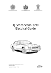
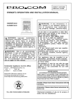
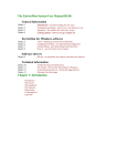
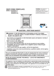
1
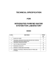
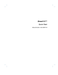
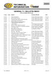
TECHNICAL
INFORMATION
CONTENTS
ELECTRICS T.I. BULLETIN INDEX
Click on bulletin title to view
Note: Some of the following bulletins, although containing electrical information, have already been issue in different
sections. They are also listed here for convenience. Click on the bulletin title to transfer to the appropriate bulletin.
T.I. No.
Issue
Subject
Products Affected
Date
Gn 008
Gn 017
Gn 018
Gn 019
GX 006
GX 017
GX 022
GX 025
GX 034
GX 037
1
1
1
1
1
1
1
2
1
1
Alternator Connections on Mainframe Harness
Perkins Engines as applicable
Starter Motors
All Perkins Engines
Magneti Marelli Service/Warranty Support
All Perkins Engines
Service Department - Computer Diagnostic Equipment
Solenoid Valve Coils - Diode Protection
SS600, PS700, SS400 Elec. Op.
Solenoid Valve Coils - Retaining Nuts & ‘O’ Rings All fitted with Solenoid Valves
Powershift Trans. Electrical Changes
All PS700
Introduction of Autoshift Transmission E.C.U.
PS700 4 Speed
Powershift Electrical Changes
Powershift
Introduction of Speed Sensor Tester
Powershift with ECU/Speed Sen.
Nov. 93
Mar. 96
Apr. 96
Nov. 97
Feb. 95
Nov. 96
Mar. 97
Nov. 98
Nov. 97
Feb. 98
EL001
EL002
EL003
EL004
EL005
EL006
EL007
EL008
EL009
EL010
1
1
1
1
1
1
1
1
1
1
ECU Diagnostics
Electrical Harness Repair Components - IP67
Electrical Harness Repair Procedure - IP67
Replacement Transmission Solenoids
Hobbs Gear Lever with Dedicated Neutral Line
Powertrain Switches
Overview of Powershift Trans. E.C.U.
Hobbs Wiper/Turn Signal Column Switch
Trans. Low Pressure Oil Light Illumination
Alternator Suppressor
Nov. 98
Dec. 98
Dec. 98
Sep. 98
Nov. 98
Nov. 98
Dec. 98
Oct. 98
Nov. 98
July 99
DATE: SEP '99
PAGE 1 OF 1
Powershift with 36 way ECU
All
All
SS600 Syncro Shuttle
All Powershift with Hobbs levers
All Powertrains
PS700 4 Speed
Part Number 475/42300
SS600 and PS700
Perkins 1000 Series
ISSUE: 2
SAFETY NOTICE - Instructions in the Service Bulletins assume
that the engineer has a sound knowledge of safety procedures and has
been trained in the maintenance and repair of ITL equipment. If you are
unsure or do not understand information contained in the Service
Bulletins then ask your supervisor or contact ITL SERVICE for advice.
Remember SAFETY MUST COME FIRST.
Number
EL001
(JCB ref: Trans003)
Issue
Date
ECU DIAGNOSTICS INSTRUCTIONS
1
Nov. 1998
Page 1 of 9
PRODUCTS AFFECTED: Powershift Transmissions with 36-Way ECU
1.
INTRODUCTION:
1.1. Literature Notation
Bold blue text refers to ITL products and part numbers.
Bold green text refers to non-ITL products, brand-names and trademarks.
&
The open book symbol denotes notes, hints and tips which are useful to remember.
The attention symbol outlines critical information which must be remembered or adhered to at all
times.
1.2. Overview
The PC Diagnostics software is supplied on the parts CD-ROM, or can be
supplied on a separate floppy disk.
The following instructions explain how to install the software onto your
computer; how to use the software and how to remove it if necessary.
This software is intended for use on IBM compatible Personal
Computers running Windows 95 or later and is not compatible with
earlier versions of Windows 3.x or Windows NT.
The software is the property of International Transmissions
Limited and is copy protected. The software may only be installed
from the original disk. Attempting to copy the software between PCs
with render the program un-usable.
THIS BULLETIN IS ISSUED FOR THE PURPOSE OF CIRCULATING TECHNICAL INFORMATION AND
DOES NOT CONSTITUTE AN INSTRUCTION TO CARRY OUT WARRANTY REPAIRS ON MACHINES.
ISSUED BY THE TECHNICAL SERVICE DEPARTMENT OF I.T.L., WREXHAM, CLWYD, LL13 9UF, UNITED KINGDOM
EL001
Page 2 of 9
2.
Issue 1
INSTALLING THE SOFTWARE:
2.1. Place the original disk into the appropriate disk drive.
2.2.
Select Run from the Start Menu.
2.3.
For CD-ROM installation type;
d:\Pc\Powershift ECU Diagnostics\setup.exe
2.4.
For Floppy Disk installation type;
a:\setup.exe
or use the
button to locate these files.
2.5.
The setup program will then start Windows 95 InstallShield Wizard, displaying the following
window;
2.6.
The dark blue setup window will then appear, maximised to the full screen size. In this main setup
window the following windows will be displayed.
2.7.
The setup program welcomes
the user and offers some helpful
advice.
Please
follow
the
recommendations
if
any
problems are encountered.
……continued
EL001
Page 3 of 9
&
At any point the user may click on;
a). the
2.8.
&
2.9.
Issue 1
button to exit,
b). the
button to continue or,
c). the
button to go back to the previous window.
Select the destination directory into which the application will be installed.
It is recommended that the default directory is used, or click on the
button to select another location.
Select the program folder in which the application is added (this also creates the links to the
application in the Start Menu)
……continued
EL001
Page 4 of 9
&
Issue 1
Again it is recommended that the default folder is used.
2.10. The setup program will then install the application onto the computer.
2.11. Wait while the program installs the files, updates the Windows 95 registry and adds the icons.
2.12. When the setup process is complete the dark blue window closes and the program folder window
can be seen open on the desktop.
At this point the installation of the Powershift ECU Diagnostics software is complete !!!
3.
RUNNING THE SOFTWARE
3.1. The simplest method of starting the software is to locate the icon in the Start Menu as shown below
3.2.
The title will appear indicating that the application is loading.
3.3.
……continued
If the ECU is not connected and powered-up then the application loads as shown below;
Page 5 of 9
3.4.
&
EL001
Issue 1
Connect the 9-pin D-type connector of the communications lead into the serial port of the PC.
Do not worry if more than one serial port (COM port, e.g. COM1, COM2 etc.. ) is present as then
software will automatically detect which port is connected to the ECU.
3.5.
Connect the other end of the communications lead into the ECU diagnostics connector provided on
the machine.
3.6.
Turn on the power to the ECU (e.g. turn the key-switch to the ignition position).
3.7.
The ECU can then be interrogated by clicking on
3.8.
The window will then
display the real-time
status of the ECU, and
example is shown below;
3.9.
the button.
……continued
The example above shows the ECU settings and status for a 4 speed manually operated ECU. (i.e.
4 gears which can be engaged independently by the operator)
EL001
Page 6 of 9
Issue 1
3.10. Please read the appropriate machine or gearbox service manual for full details of how to use this
software to diagnose electrical faults on the transmission.
3.11. Should there be a problem with the communications then the following error message will appear.
3.12. The ECU can detect if there is a problem with the gearbox solenoids or the associated
interconnections. On ‘Scanning’ the ECU, if such an error is detected them the following error
message will appear.
3.13. The faulty solenoid / connection can pinpointed within the software as explained in the next section.
3.14. If the above warning is displayed, or to look at the Solenoid Status at any time then click on
the
button.
The Unit Status section (bottom right corner) of the window, showing the status of the ECU inputs
and present gear selection, will freeze whilst doing this operation. The left half of the window will also
‘grey-out’.
3.15. Faulty solenoids or connections will be shown highlighted. In the example below we can see that all
the solenoids are faulty. (This would mean that the gearbox harness is not connected.)
……continued
3.16. The solenoid name will be seen to become un-highlighted as the fault is cured
3.17. Click
on
window.
the button to exit this feature and to unfreeze the rest of the
EL001
Page 7 of 9
4.
Issue 1
REMOVING THE SOFTWARE
4.1. Start up the control panel from the Start Menu.
4.2.
Double-click on the Add/Remove Programs icon.
4.3.
……continued
From the Add/Remove Programs Properties window select the Powershift ECU Diagnostics item
and click on the
button.
Page 8 of 9
EL001
Issue 1
4.4.
Confirm that the application is to be removed by clicking on
the button.
4.5.
The Windows 95 InstallShield (used to install the application) will then remove the software
completely.
……continued
4.6.
All icons, shortcuts and folders will be removed automatically by Windows 95.
Page 9 of 9
5.
EL001
Issue 1
ADDITIONAL INFORMATION
This software does not support diagnostics of the earlier range of ITL Powershift Controllers in the 18Way housing. To diagnose faults on machine electrical systems fitted with the 18-Way ECUs a dedicated
Handheld Test Unit (MkII) is available (Part No. 892/00943). This Test Unit is supplied with its own
handbook (Publication No. 9801/0166) which includes operating instructions, fault finding guide and tips
on common faults.
The Powershift ECU Diagnostics software complements the range of diagnostics software available for
the PSION Workabout, the standard ITL diagnostics tool.
For further details on the diagnostics software for the PSION Workabout please read the relevant
literature on the ITL CD-ROM.
INDEX
TECHNICAL
INFORMATION
! SAFETY NOTICE - Instructions in the Service Bulletins assume that the
engineer has a sound knowledge of safety procedures and has been trained in the
maintenance and repair of ITL equipment. If you are unsure or do not understand
information contained in the Service Bulletins then ask your supervisor for advice.
Remember SAFETY MUST COME FIRST.
Electrics
Number
EL002
(JCB 2/174; C45/N.Am.)
Issue
Date
SUBJECT:
Electrical Harness Repair Components - IP67 Standards
PRODUCTS AFFECTED:
All
TO BE CARRIED OUT:
For Information Only
1
Dec. 1998
Page 1 of 2
SERVICE INFORMATION:
Instances do occur where it is necessary to incorporate auxiliary electrical components into existing electrical circuits
and repair or replace specific individual wires or connectors.
This bulletin introduces part numbers for various electrical connectors and terminals used in JCB IP67 wiring
harnesses. The bulletin should also be read in conjunction with Electrical Bulletin EL003.
! CAUTION: When installing Auxiliary Electrical Components always ensure that the additional load rating is
suitable for that particular circuit. It is not recommended to increase the fuse rating as this can cause
overloading and consequential failure of wiring, along with failure of integral circuit components, which the
fuse is protecting.
Packard
Connector
Sumitumo
Connector
Econoseal
Connector
270470
270480
270490
Splices
Hirschmann
Connector
270500
270510
ITT Canon
Connector
270520
FLYING LEADS
AMP
(Relay Term.)
Pozilock
AMP Jnr.
Connector
Relay &
Base
270540
270530
270550
Pressac Fuse
Blade
THIS BULLETIN IS ISSUED FOR THE PURPOSE OF CIRCULATING TECHNICAL INFORMATION AND DOES
NOT CONSTITUTE AN INSTRUCTION TO CARRY OUT WARRANTY REPAIRS ON MACHINES
ISSUED BY THE TECHNICAL SERVICE DEPARTMENT OF I.T.L., WREXHAM, CLWYD, LL13 9UF, UNITED KINGDOM
Page 2 of 2
PART No
DESCRIPTION
EL002
TYPE
PART No
Issue 1
DESCRIPTION
TYPE
7201/0008
FUSE BOX TERMINAL 0.5 - 1.25mm
PR.
7219/0002
10 WAY PIN HOUSING
SUM.
7201/0009
FUSE BOX TERMINAL 1.0 - 3.2mm
PR.
7219/0003
10 WAY PIN RETAINER
SUM.
7201/0010
FUSE BOX TERMINAL 2.5 - 6.0mm
PR.
7219/0004
10 WAY RECEPTICAL RETAINER
SUM.
7201/0427
RELAY BASE TERMINAL 0.5 - 1.0mm
AMP
7219/0005
14 WAY RECEPTICAL HOUSING
SUM.
7201/0428
RELAY BASE TERMINAL 4.0 - 6.0mm
AMP
7219/0006
14 WAY PIN HOUSING
SUM.
7201/0429
RELAY BASE TERMINAL 1.3 - 3.4mm
AMP
7219/0007
14 WAY PIN RETAINER
SUM.
7210/0001
DUMMY PLUG
SUM.
7219/0008
14 WAY RECEPTICAL RETAINER
SUM.
7210/0008
DUMMY PLUG
PACK.
7220/0001
31 WAY RECEPTICAL BULKHEAD HOUSING
ITT
7210/0015
DUMMY PLUG
ECON.
7220/0002
31 WAY PIN HOUSING
ITT
7210/0017
DUMMY PLUG
AMP
7220/0003
31 WAY PIN BULKHEAD HOUSING
ITT
7211/0001
1 WAY PIN HOUSING
PACK.
7220/0004
31 WAY RECEPTICAL HOUSING
ITT
7211/0002
1 WAY RECEPTICAL HOUSING
PACK.
7220/0005
4 WAY PIN BULKHEAD HOUSING
ITT
7212/0001
2 WAY RECEPTICAL HOUSING
SUM.
7220/0006
4 WAY RECEPTICAL HOUSING
ITT
7212/0002
2 WAY PIN HOUSING
SUM.
7220/0007
32 WAY RECEPTICAL HOUSING
ITT
7212/0003
2 WAY PIN RETAINER
SUM.
7220/0008
32 WAY PIN BULKHEAD HOUSING
ITT
7212/0004
2 WAY RECEPTICAL RETAINER
SUM.
7220/0009
19 WAY PIN BULKHEAD HOUSING
ITT
7212/0005
2 WAY RECEPTICAL HOUSING
PACK.
7220/0010
19 WAY RECEPTICAL HOUSING
ITT
7212/0006
2 WAY PIN HOUSING
PACK.
7220/0012
48 WAY RECEPTICAL HOUSING
ITT
7212/0008
2 WAY RECEPTICAL HOUSING
ECON.
7220/0013
48 WAY PIN BULKHEAD HOUSING
ITT
7212/0009
2 WAY RECEPTICAL RETAINER
ECON.
7220/0014
18 WAY ECONOSEAL RECEPTICAL RETAINER
ECON.
7212/0014
2 WAY METRIPACK RECEPTICAL HOUSING
PACK.
7220/0015
18 WAY ECONOSEAL RECEPTICAL HOUSING
ECON.
7212/0015
3 WAY METRIPACK RECEPTICAL RETAINER
PACK.
7220/0016
36 WAY ECONOSEAL RECEPTICAL RETAINER
ECON.
7212/0020
2 WAY J/TIMER RECEPTICAL HOUSING
AMP
7220/0017
36 WAY ECONOSEAL RECEPTICAL HOUSING
ECON.
7212/0021
2 WAY J/TIMER HOUSING
AMP
7231/0001
SINGLE RELAY BASE SLOT-IN-TYPE
RELAY
7213/0001
3 WAY RECEPTICAL HOUSING
SUM.
7232/0002
SWITCH LIGHT BULB HOLDER
SWF
7213/0002
3 WAY PIN HOUSING
SUM.
7233/0010
HIRSCHMANN PLUG SEAL
HIRSCH.
7213/0003
3 WAY PIN RETAINER
SUM.
7234/0003
IGNITION SWITCH PLUG (1)
MERIT
7213/0004
3 WAY RECEPTICAL RETAINER
SUM.
7236/0003
IGNITION SWITCH PLUG (2)
MERIT
7213/0005
3 WAY RECEPTICAL HOUSING (DT)
SUM.
7238/0001
8 WAY SWITCH BASE PLUG
SWF
7213/0006
3 WAY PIN HOUSING (DT)
SUM.
892/00350
BUTANE HEATER ASSEMBLY
7213/0007
3 WAY PIN RETAINER (DT)
SUM.
892/00351
SPLICE 0.5 - 1.5mm - RED
7213/0008
3 WAY RECEPTICAL RETAINER (DT)
SUM.
892/00352
SPLICE 1.5 - 2.5mm - BLUE
7213/0009
3 WAY RECEPTICAL HOUSING
PACK.
892/00353
SPLICE 3 - 6mm - YELLOW
7213/0010
3 WAY PIN HOUSING
PACK.
892/00869
PIN / RECEPTICAL REMOVAL TOOL (POWER)
ITT
7214/0001
4 WAY RECEPTICAL HOUSING
SUM.
892/00870
PIN / RECEPTICAL REMOVAL TOOL (SIGNAL)
ITT
7214/0002
4 WAY PIN HOUSING
SUM.
993/56700
FLYING LEAD SUMITOMO 1mm
SUM.
7214/0003
4 WAY PIN RETAINER
SUM.
993/56800
FLYING LEAD SUMITOMO 2mm
SUM.
7214/0004
4 WAY RECEPTICAL RETAINER
SUM.
993/56900
FLYING LEAD PACKARD 1mm
PACK.
7214/0005
4 WAY RECEPTICAL HOUSING (INLINE)
PACK.
993/57000
FLYING LEAD PACKARD 2mm
PACK.
7214/0006
4 WAY PIN HOUSING (INLINE)
PACK.
993/57100
FLYING LEAD 90DEGREE POZILOCK 1mm
POZI.
7214/0007
4 WAY PIN HOUSING (BLOCK)
PACK.
993/57200
FLYING LEAD 90DEGREE POZILOCK 2mm
POZI.
7214/0008
4 WAY RECEPTICAL HOUSING (BLOCK)
PACK.
993/57300
FLYING LEAD 2mm
RELAY
7214/0009
4 WAY ECONOSEAL PIN HOUSING
ECON.
993/57400
FLYING LEAD 3mm
RELAY
7214/0010
4 WAY ECONOSEAL RECEPTICAL HOUSING
ECON.
993/57500
FLYING LEAD POZILOCK & FUSE BLADE 2mm
POZI.
7214/0011
4 WAY ECONOSEAL PIN RETAINER
ECON.
993/57600
FLYING LEAD POZILOCK & FUSE BLADE 3mm
POZI.
7214/0012
4 WAY ECONOSEAL RECEPTICAL RETAINER
ECON.
993/57700
FLYING LEAD POZILOCK & FUSE BLADE 4mm
POZI.
7216/0001
6 WAY RECEPTICAL HOUSING
SUM.
993/57800
FLYING LEAD 1mm
RELAY
7216/0002
6 WAY PIN HOUSING
SUM.
993/57900
FLYING LEAD ITT CANON 1mm (SIGNAL)
ITT
7216/0003
6 WAY PIN RETAINER
SUM.
993/58000
FLYING LEAD ITT CANON 1.5mm (SIGNAL)
ITT
7216/0004
6 WAY RECEPTICAL RETAINER
SUM.
993/58100
FLYING LEAD ITT CANON 2mm (SIGNAL)
ITT
7216/0005
6 WAY RECEPTICAL HOUSING
PACK.
993/58200
FLYING LEAD ITT CANON 3mm ( POWER)
ITT
7216/0006
6 WAY PIN HOUSING
PACK.
993/58300
FLYING LEAD ITT CANON 4mm (POWER)
ITT
7216/0007
6 WAY ECONOSEAL RECEPTICAL HOUSING
ECON.
993/58400
FLYING LEAD AMP J/TIMER 1mm
AMP
7216/0008
6 WAY ECONOSEAL RECEPTICAL RETAINER
ECON.
993/58500
FLYING LEAD AMP J/TIMER 2mm
AMP
7216/0009
6 WAY ECONOSEAL PIN HOUSING
ECON.
993/58600
FLYING LEAD AMP POZLK & FUSE BLADES 1mm
POZI.
7216/0010
6 WAY ECONOSEAL PIN RETAINER
ECON.
993/69600
AMP. JUNIOR TIMER 2mm
AMP
7216/0011
6 WAY ECONOSEAL PANEL MOUNT PIN HSG.
ECON.
998/00001
FLYING LEAD ECONOSEAL 1mm
ECON.
7218/0001
8 WAY RECEPTICAL HOUSING
SUM.
998/00002
FLYING LEAD ECONOSEAL 1.5mm
ECON.
7218/0002
8 WAY PIN HOUSING
SUM.
7218/0003
8 WAY PIN RETAINER
SUM.
PR = Pressac; SUM. = Sumitumo; Pack. = Packard; Econ. = Econoseal;
7218/0004
8 WAY RECEPTICAL RETAINER
SUM.
Pozi. = Pozilock;
7219/0001
10 WAY RECEPTICAL HOUSING
SUM.
INDEX
TECHNICAL
INFORMATION
! SAFETY NOTICE - Instructions in the Service Bulletins assume that the
engineer has a sound knowledge of safety procedures and has been trained in the
maintenance and repair of ITL equipment. If you are unsure or do not understand
information contained in the Service Bulletins then ask your supervisor for advice.
Remember SAFETY MUST COME FIRST.
SUBJECT:
Electrical Harness Repair Procedure - IP67 Standards
PRODUCTS AFFECTED:
All
TO BE CARRIED OUT:
For Information Only
Electrics
Number
EL003
(JCB Gen 021)
Issue
Date
1
Dec. 1998
Page 1 of 3
SERVICE INFORMATION:
Instances do occur where it is necessary to incorporate auxiliary electrical components into existing electrical circuits
and repair or replace specific individual wires within a harness.
To ensure that either the inclusion of an auxiliary electrical component or a repair within a harness is actioned to an
acceptable standard it is strongly recommended that the following tools, equipment and procedures are always used
to ensure the installation is maintained to IP.67 standards.
The sheath covering of the recommended splice is heat shrunk onto the original wire insulation. This results in a seal
and corresponding joint to IP 67 specifications.
! CAUTION: When installing Auxiliary Electrical Components always ensure that the additional load rating is
suitable for that particular circuit. It is not recommended to increase the fuse rating as this can cause overloading and
consequential failure of wiring, along with failure of integral circuit components, which the fuse is protecting.
! WARNING:In addition to the warnings incorporated into the procedure, extreme care should be taken when
handling the gas heating tool to ensure that the flame does not damage or set fire to any items in the vicinity of the
repair, i.e. other wires, floor panels, floor mats, sound proofing, paintwork. etc. This tool should not be used in any
restricted location prohibiting the use of "Naked Flames' or where risk of explosive gas or similar safety parameters
apply. No other heat source should be used to attempt a sealed joint .
TOOLS REQUIRED:
892/00350
892/00349
892/00351
892/00352
892/00353
Butane Heater assembly
Crimp tool
Splice 0.5-1.5 mm (Red)
Splice 1.5-2.5 mm (Blue)
Splice 3.0-6.0 mm (Yellow)
1
1
50
50
50
THIS BULLETIN IS ISSUED FOR THE PURPOSE OF CIRCULATING TECHNICAL INFORMATION AND DOES
NOT CONSTITUTE AN INSTRUCTION TO CARRY OUT WARRANTY REPAIRS ON MACHINES
ISSUED BY THE TECHNICAL SERVICE DEPARTMENT OF I.T.L., WREXHAM, CLWYD, LL13 9UF, UNITED KINGDOM
Page 2 of 3
EL003
Issue 1
PROCEDURE:
1
Cut the wire and remove the protective insulation for a suitable distance dependent upon the size of wire and
splice to be used. For the splices detailed on page 1, the dimension is 7mm.
2
Using the correct sized splice, attach the new section of wire required or auxiliary flying lead to the existing
harness and secure using the crimp tool X, part number 892/00349.
Note that each of the splices detailed is colour-coded to make size and range readily visible. They are secured
using the corresponding size and matching colour-coded jaws of the crimp tool to ensure joint security. This tool
also incorporates a ratchet closing mechanism which will not release until the splice is fully closed to the correct
compression size.
3
With the Butane heater assembly, 892/00350, seal the connection using the procedure on the next page.
7
X
189530
Page 3 of 3
EL003
Issue 1
C
A
F
E
D
B
S189490/1
With the Butane Heater
assembly 892/00350, seal
the connection using the
following procedure.
3.1 Remove the cap A from
the end of the disposable gas cartridge
B.
S189490/2
3.2 Before assembling the
gas cartridge to the
reflector element C, turn
the red ring D to the left,
(in the direction of the
minus sign marked on
the ring).
S189490/3
3.3 Position
the
tube
hanging down from
inside the reflector
assembly into the hole
at the top of the gas
cartridge. Then press
the gas cartridge up into
the reflector assembly
as far as possible until
the two elements are
clasped firmly together.
A click will be heard.
S189490/4
3.4 Turn the small ring E so
that the air holes at F
are completely closed.
G
G
F
E
D
S189490/5
3.5 Turn the red ring D to
the right (in the direction
of the plus sign) in order
to turn on the gas.
IMPORTANT: Before turning
the heater on, make sure
that the cartridge is not hotter
than the reflector element.
This may occur if the
cartridge is held in the hand
for a long time. The
temperature
difference
between the cartridge and
the reflector element may
cause long yellow flames to
appear on ignition.
S189490/6
3.6 Hold
the
heater
vertically and, using a
match or cigarette lighter,
light the gas as shown.
Note: The fact that the
sound of liquid cannot be
heard when the cartridge is
shaken does not mean it is
empty. No sound will be
heard even when the
cartridge is full.
Hold the heater vertically for
1 to 2 minutes until the
catalytic reaction occurs.
This is indicated when the
blue flame fades and the
ceramic element glows red.
Then turn the small ring E
until the air holes at F are
completely open. The tool is
ready for use.
S189490/7
The heater can be used in
two modes:
3.7 Side wings G down,
reflector head completely open. In this
mode the infra red heat
waves are dominant
(recommended for the
light coloured plastic
splices).
S189490/8
3.8 Side wings G up,
reflector head opening
reduced. In this mode
the heating is done only
by the hot gas (use for
dark coloured plastic
splices).
To switch off the heater, turn
the red ring D to the left (in
the direction of the minus
sign).
! CAUTION
When the heater is in use, the reflector and the air
coming out are extremely hot. Keep away to avoid
accidental burns. Do not touch the reflector until it has
had time to cool down after switching off. If flame
reappears at the reflector when the heater is in use, the
catalytic element is damaged or used up. Stop work
immediately and replace the heater.
INDEX
TECHNICAL
INFORMATION
! SAFETY NOTICE - Instructions in the Service Bulletins assume that the
engineer has a sound knowledge of safety procedures and has been trained in the
maintenance and repair of ITL equipment. If you are unsure or do not understand
information contained in the Service Bulletins then ask your supervisor for advice.
Remember SAFETY MUST COME FIRST.
Electrics
Number
EL004
(JCB Gen 085; C65/N. Am.)
Issue
Date
1
Sep. 1998
SUBJECT:
Replacement Transmission Solenoids
Page 1 of 1
PRODUCTS AFFECTED:
Forward and Reverse Solenoids Fitted To ITL SS600 Syncro Shuttle Transmissions
TO BE CARRIED OUT:
For Information Only
SERVICE INFORMATION:
Replacement transmission solenoids with connectors type A have been superseded to the current connector type B.
To change this type of connector the machine harness will have to be modified by splicing on a new connector C.
Refer to JCB T.I. 2/174 (C45 N. Am.) March 1997 and JCB General Bulletin 020 (C30 N. Am.) Feb. 93.
Solenoids with connectors type D have also been superseded to the current type connector type B. To enable this
type of connecter to be used, link harness E is available for service use.
SERVICE PROCEDURE:
IMPORTANT NOTE: All later solenoids have diodes built into the coils. The diodes will be damaged if the coil is
connected with reverse polarity causing the coil to fail and the fuse to blow.
Identify the positive wire on the machine, note the solenoid coil is marked positive and negative, connect the wires
into the new connector the correct way round as shown at F.
Ensure the wire seals G are fitted to the plug to prevent water
ingress.
F
PARTS INFORMATION
Item
C
E
Part Number
993/69600
718/44900
Description
Connector
Link Harness
B
A
D
C
THIS BULLETIN IS ISSUED FOR THE PURPOSE OF CIRCULATING TECHNICAL INFORMATION AND DOES
NOT CONSTITUTE AN INSTRUCTION TO CARRY OUT WARRANTY REPAIRS ON MACHINES
ISSUED BY THE TECHNICAL SERVICE DEPARTMENT OF I.T.L., WREXHAM, CLWYD, LL13 9UF, UNITED KINGDOM
INDEX
TECHNICAL
INFORMATION
! SAFETY NOTICE - Instructions in the Service Bulletins assume that the
engineer has a sound knowledge of safety procedures and has been trained in the
maintenance and repair of ITL equipment. If you are unsure or do not understand
information contained in the Service Bulletins then ask your supervisor for advice.
Remember SAFETY MUST COME FIRST.
Electrics
Number
EL005
Issue
Date
1
Nov. 1998
SUBJECT:
Introduction of Hobbs Gear Lever with Dedicated Neutral Line
Page 1 of 2
PRODUCTS AFFECTED:
All Powershift Transmissions with Hobbs ITL supplied forward and reverse levers
TO BE CARRIED OUT:
Information only
SERVICE INFORMATION:
A new Powershift forward, reverse and speed change lever, lTL part number 475/51090, was introduced from July
1998 in order to simplify OEM wiring.
The new lever has a different 12 pin Deutsch wiring connection and provides a dedicated neutral circuit feed.
The previous lever 475/42100 with 8 pin connection will remain available for service use.
ln order to fit the new lever in place of the old lever the machine wiring must be modified by adding an additional
explicit neutral feed to the transmission ECU and changing the harness plug.
Additional Information
1
ITL notification of change 0705 applies.
2
- Wiring connection (and the lever) should be protected from pressure washing or hot water/steam cleaning
particularly if washing chemicals are used.
- A suitable shroud around the wiring connections on non cabbed machines is recommended to protect the wiring
connection from direct water jets.
Parts Information
Description
Gear Lever
Part Number
475/51090
cont’d
THIS BULLETIN IS ISSUED FOR THE PURPOSE OF CIRCULATING TECHNICAL INFORMATION AND DOES
NOT CONSTITUTE AN INSTRUCTION TO CARRY OUT WARRANTY REPAIRS ON MACHINES
ISSUED BY THE TECHNICAL SERVICE DEPARTMENT OF I.T.L., WREXHAM, CLWYD, LL13 9UF, UNITED KINGDOM
Page 2 of 2
EL005
The illustrations show both a gear switch A and a multifunction switch B. Item A incorporates a locating pin X which
engages with a drilled hole in the column to ensure correct
location and prevents rotation of the switch mounting. The two
switches are clamped onto the shaft using two screws D. If
item B is not required, mounting clamp C should be used
instead.
Issue 1
A
C
The gear switch incorporates a rotary selector for gears 1, 2,
3, 4 and a horn button (or kickdown button). Forward/Reverse
selection is made by lifting the lever out of its neutral (detent)
position and moving it forward (for forward direction) or back
(for reverse direction).
D
X
B
Note: An explicit neutral line is incorporated to simplify the
neutral start circuit (i.e. no additional relays are required to
decode neutral).
Gear Switch Connections Y
9 10 11 12
1
1
8
2
2
7
3
3
9 10 11 12
4
4
8
5
2
6
R
5
Z
Y
6
7
1st gear
2nd gear
3rd gear
4th gear
Horn (or kickdown) load
Reverse
Forward
Neutral
Feed
6
1
2
3
4
6
7
9
11
12
7
7
8
N
11
12
1
9
2
3
3
1
1
4
5
2
4
10
11
3
9
4
A302480
A302480
12.5
ø6
R
N
Deutsch Mating Connector Requirements
Item
6
F
Multi-function Switch Connections Z
1
Flasher mode
2
Washer feed
3
High beam
4
Headlamp feed
5
Low beam
6
Wiper park
7
Wash/Wipe load
8
Wiper feed
9
Left turn
10 Right turn
11 Turn signal feed
Deutsch Part No. ITL Part No. Qty.
Y
E
F
ø45
12.5
Housing (12 way)
Terminal Socket
Contact (female)
Locking Wedge
Seal Plug
DT06-12S
1062-16--0122
0462-201-16141
W12S
114017
460/34901
1
460/34702
460/34902
460/34903
1
6
ø45
E
A302280
Connectors E must be protected by a suitable cover against
damage and high pressure washes.
INDEX
TECHNICAL
INFORMATION
! SAFETY NOTICE - Instructions in the Service Bulletins assume that the
engineer has a sound knowledge of safety procedures and has been trained in the
maintenance and repair of ITL equipment. If you are unsure or do not understand
information contained in the Service Bulletins then ask your supervisor for advice.
Remember SAFETY MUST COME FIRST.
SUBJECT:
Powertrain Switches
PRODUCTS AFFECTED:
All Powertrains
TO BE CARRIED OUT:
For Information only
Electrics
Number
EL006
Issue
Date
1
Nov. 1998
Page 1 of 2
SERVICE INFORMATION:
This Technical bulletin is issued to answer typical service questions relating to Powertrain switches supplied to OEMs
by ITL.
Note: Some OEMs use their own switches.
1
The table on page 2 indicates the switch description, thread, locations, part number and operating values. Contact
ITL Technical Sales if further details are required.
2
The most common reason for switch failure is water ingress into the switch through the terminals because of
defective or incorrect harness connections.
ITL now supplies certain switches loose rather than fitted to the powertrain to help prevent water ingress during
storage or shipping.
Always protect switches during pressure washing especially if cleaning chemicals or steam (hot) pressure washes
are used.
Later ITL switches (from mid ‘97) have an Epoxy resin sealer added to help protect switches against defective
wire seals.
4
Adaptor item ‘H’ 997/22100 can be used in conjunction with switch item ‘D’ 701/41600 for converting older pre ‘95
transmissions with the test point and previous type pressure switch (with “spade connections” on a separate ‘T’
piece) to the current switch.
An ‘AMP junior timer’ link harness item ‘J’ 993/69600 is available for modifying machine harnesses.
5
‘AMP junior timer’ switch harness connections are available from ITL for OEMs who are unable to source from
AMP.
Note: ITL can provide 2-Way “AMP Junior Timer” plug kits complete with housing, terminals and wire seals
(460/34600).
THIS BULLETIN IS ISSUED FOR THE PURPOSE OF CIRCULATING TECHNICAL INFORMATION AND DOES
NOT CONSTITUTE AN INSTRUCTION TO CARRY OUT WARRANTY REPAIRS ON MACHINES
ISSUED BY THE TECHNICAL SERVICE DEPARTMENT OF I.T.L., WREXHAM, CLWYD, LL13 9UF, UNITED KINGDOM
Page 2 of 2
EL006
Issue 1
Sensor Switch Positions
A
B
C
D
S302210
Sensor switch A for transmission oil temperature is fitted in
transmission oil cooler.
E
Sensor switch G for vacuum detection is fitted in the engine
air cleaner.
F
H
A301870
J
G
A310200
Part No.
Colour
Thread
Size
Function
Operating
Value
Sealing Washer
Part No.
A
701/71300
Green
5/8”
UNF
Trans Oil Temperature Switch
110 °C ±5
1406/0014
B
701/37400
Yellow
5/8”
UNF
Engine Water Temperature Switch
102 °C ±5
1406/0014
C
716/12800
Red
NPTF
Engine Water Temperature Sender
-
Seal with PTFE Tape
D
701/41600
Red
Trans Oil Pressure Switch SS600
40PSI
1406/0011
E
701/43700
Grey
BSP
Trans Oil Pressure Switch PS700
40PSI
1406/0015
F
701/41500
Tan
1/8”
NPTF
Engine Oil Pressure Switch
30 - 50 PSI
Seal with PTFE Tape
G
701/36500
Black
1/8”
NPTF
Vacuum Sensor Switch
55 mbar
Seal with PTFE Tape
H
997/22100
N/A
M10 x 1 x M12 x 1 Tee Adapter
N/A
Seal with PTFE Tape
J
993/69600
N/A
AMP Junior Timer Link Harness
N/A
N/A
1/2”
M12 x 1mm
3/8”
1/4”
BSP
N/A
INDEX
TECHNICAL
INFORMATION
! SAFETY NOTICE - Instructions in the Service Bulletins assume that the
engineer has a sound knowledge of safety procedures and has been trained in the
maintenance and repair of ITL equipment. If you are unsure or do not understand
information contained in the Service Bulletins then ask your supervisor for advice.
Remember SAFETY MUST COME FIRST.
Electrics
Number
EL007
Issue
Date
1
Dec. 1998
OVERVIEW OF POWERSHIFT TRANSMISSION ECU (460/378xx)
Page 1 of 4
PRODUCTS AFFECTED: PS700 4 Speed Transmissions
INTRODUCTION:
The driveline comprises a Powershift transmission controlled by an Electronic Control Unit
(E.C.U.). This provides the operator with manual selection of gears with added
protection for both operator and transmission. In addition, a kickdown function is
incorporated allowing the operator to temporarily select a lower gear if conditions
demand.
2)
KEY COMPONENTS:
Transmission:
The existing 4 speed Powershift transmission has a speed sensor fitted to detect the
speed of rotation of the output shaft. This information provides road speed information
to the E.C.U. (see below).
E.C.U.:
The 18/36 way type E.C.U. is a new component which replaces older 18/18 way type
E.C.U’s (460/315xx). It is a Solid State, microprocessor-based, electronics "black box".
Based upon data supplied from the column switch, kickdown button, (see Controls/
Instrumentation below), parkbrake switch, transmission dump switch and the speed
sensor, the E.C.U. controls the gear selection solenoid valves on the transmission.
18-Way
Connector
000/00000
1)
36-Way
Connector
Controls/Instrumentation:
The column switch is the same as non E.C.U. transmissions (475/51090). The gears are selected on the
Forward, Neutral, Reverse (FNR) lever rotary switch, positions "1", "2", “3” and "4" manually selecting those
gears as machine conditions allow.
An optional kickdown button can be fitted by the OEM (e.g. button on loader lever). If the kickdown is pressed,
the next lowest gear is selected. By pressing kickdown again, the transmission will revert to the previous higher
gear. Selecting reverse or another gear will also cancel the kickdown.
An optional input for connection to the parkbrake warning light switch is available. This places the transmission in
neutral whenever the parkbrake is operated, regardless of any other requested condition. If the operator tries to
select forward or reverse direction whilst the parkbrake is still applied then the E.C.U. will sound a continuous
tone on the warning buzzer whilst still holding the transmission in neutral. This feature improves parkbrake life as
in lower gears the transmission can easily drive with the parkbrake engaged.
...... continued
THIS BULLETIN IS ISSUED FOR THE PURPOSE OF CIRCULATING TECHNICAL INFORMATION AND DOES
NOT CONSTITUTE AN INSTRUCTION TO CARRY OUT WARRANTY REPAIRS ON MACHINES
ISSUED BY THE TECHNICAL SERVICE DEPARTMENT OF I.T.L., WREXHAM, CLWYD, LL13 9UF, UNITED KINGDOM
Page 2 of 4
EL007
Issue 1
An optional input for a Four Wheel Drive (4WD) command signal is provided so that the operator may manually
select 4WD. Note that 4WD will automatically disengage in 3rd and 4th gears to prevent drive line ‘wind-up’.
Further control of the 4WD facility can be had by connecting the ‘Footbrake’ input to the tail light brake switch.
Thus 4WD will be engaged whenever the operator uses the foot operated brakes. This feature operates in all
gears, providing Four Wheel Braking (4WB).
The warning buzzer and red warning light on the instrument panel will be activated if a gear selection is made
which is not allowed by the E.C.U. software (see System logic). This comprises a double-bleep which will
continue either until the selection conditions are met, or the request is de-selected. For a non-allowed kickdown
request, the buzzer will double-bleep only once at the time of the request.
3)
SYSTEM LOGIC
The E.C.U. will not allow gear changes to occur if outside the pre-programmed conditions. The following
description explains the system logic.
Gearshifting:
• 1st, 2nd, 3rd and 4th gears are selected in the normal way on the column switch, upshifts are engaged
immediately on request.
• The E.C.U. does not allow downshifts above certain speeds. If attempted, a double-bleep will sound and the
transmission remains in its current gear until the speed has reduced sufficiently to allow a downshift to occur.
Upshifting is not speed limited.
• A change in direction can be made as long as the machine speed is below a specifically assigned value.
• If 4WD is selected for the machine, 4WD is disengaged in 4th gear.
Kickdown facility - Manual mode
• Pressing the kickdown button will result in a gear change to the next lowest gear.
• Kickdown operation is subject to the same pre-programmed speed limits as downshifts. If a non-allowed
kickdown is requested, kickdown will not occur. The buzzer will sound a double-bleep. Note that the E.C.U.
does not retain the kickdown request in its memory, so kickdown will have to be re-selected once the
machine speed has reduced.
• The transmission will revert to the original gear either by selecting a directional or gear change on the FNR
lever or by pressing the kickdown button again, or when the pre-programmed time delay expires (default = 6
seconds).
Note: Care is to be taken when downshifting, either by kickdown or manual selection on the column switch. It is
recommended that downshifting is not requested at high speed, relying on the downshift protection system to
avoid sudden deceleration. The downshift protection system is to reduce loads on the transmission, thereby
improving its life, and is not to be used as a means of pre-selecting a downshift when slowing down. If the speed
sensor fails, (see "Get you home" facility, next page), downshift protection will not be available.
ECU Power-up operation:
• A single double-beep is sounded to indicate the E.C.U. has been powered-up.
Note: On machine power-up this indication may be overshadowed by other alarm sounds. However this doublebeep can be a useful aid to diagnosing intermittent E.C.U. power loss.
•
If the machine is stationary then the E.C.U. holds the transmission in neutral until the FNR lever is placed in
or passed through the neutral position.
•
If the machine is moving when the E.C.U. is powered-up then the E.C.U. will select the appropriate gear for
the given road speed.
Warning buzzer/light:
• A double-bleep will sound for the following reasons;
Kickdown or manual downshift selected when machine speed is above the pre-programmed limit.
Single double-beep on power-up (or on resumption of power supply).
......continued
Page 3 of 4
3)
EL007
Issue 1
SYSTEM LOGIC (continued)
"Get you home" facility:
• If the speed sensor fails, the buzzer will not sound. All gears will be available with kickdown but there will be
no downshift speed protection. Care is to be taken when downshifting with either kickdown or gear
selection on the column switch. On restarting the machine, 4th gear will be disabled to indicate to the
operator that a fault has occurred and to limit the maximum speed.
Diagnostics facility:
• A 6-way AMP Econoseal connector must be provided by the OEM to allow connection by the service
engineer to the on-board E.C.U. fault diagnostics system.
• Service Edition Diagnostics software available for use with Psion Handheld Computer (ITL Standard
Diagnostics Tool) or Personal Computer running Windows 95 (operating instructions are available for both
formats). This software is intended for non-intrusive Diagnostics by OEM and/or approved agent(s).
• A communications lead is available from ITL, part number 892/00952.
Machine performance:
• The overall machine performance is unchanged by the Powershift E.C.U. feature. All other features of the
transmission will be as the current products without E.C.U.
IMPORTANT - Non ITL standard Powershift E.C.U. features.
This T.I. details the standard Powershift E.C.U. only. Note that the OEM may request different features from the
standard Powershift E.C.U., for example, inhibiting 4th gear (as different country legislation requires).
The OEM must ensure:
• The OEM operator handbook details all features, including relevant non-standard E.C.U. features and logic.
• The OEM service information details E.C.U. differences from the ITL manual.
• All changes to the original E.C.U. settings or features supplied by ITL are approved in writing, including
completion of the ITL E.C.U. engineering sign off document and the OEM’s own F.M.E.A. analysis carried
out.
• The OEM service network and all OEM customers are informed accordingly of the correct operating and
service procedures, including SAFETY risk assessment.
If you do not fully understand how the E.C.U. functions read the relevant ITL service manual and technical
information, or contact ITL, before operating the machine or carrying out service work.
E.C.U. Re-programming
It is possible to tailor an existing production E.C.U. to refine the control of the transmission. The OEM may consider
making changes to the E.C.U. at the prototyping or pre-production stages of a machines’ development if the OEM
feels that this would be significantly beneficial to machine operation. It is recommended that changes are not made to
E.C.U’s fitted to production machines. (However this flexibility is useful if a critical error between E.C.U. and
application compatibility is discovered after a machine has been production released or the machine is in a special
application, e.g. speed limiting required.)
IMPORTANT - It is vitally important that modifications to any E.C.U. settings are carried out only by the OEM.
Any operator making changes must be trained and competent in the practice of making alterations to E.C.U.
settings. Changes should only be carried out if their effect is judged to improve machine performance
significantly. All changes must be approved and recorded by ITL as stated above.
Using specifically designed Diagnostics software for the PSION or PC (detailed re-programming instructions are
available for both formats) it is possible to change the following characteristics of the E.C.U.:
•
•
•
•
Down-shift and Kickdown speeds.
Kickdown timer (use and duration).
Gear-shift lever interpretation.
Specific gear inhibiting.
Page 4 of 4
EL007
Issue 1
WARRANTY INFORMATION
Any E.C.U. which is claimed or returned under warranty will not be accepted unless the ECU settings are approved by
ITL or are unchanged.
Almost without exception, E.C.U’s which have been claimed or returned as defective are found to have been
incorrectly diagnosed or installed and therefore either work correctly when tested/reset or the fault is later identified to
be outside the E.C.U., e.g. switches or wiring.
An intermittent fault is not an indication of E.C.U. failure but indicates another cause which should be investigated
before changing the E.C.U. (see T.I. Gn019 and the ITL service manual for further information on testing)
Note that a charge may be made for testing or for return carriage of correctly operating E.C.U’s which have been
service tested by ‘substitution’ then returned under warranty or had the E.C.U. settings deviated from the original ITL
settings without approval.
INDEX
TECHNICAL
INFORMATION
! SAFETY NOTICE - Instructions in the Service Bulletins assume that the
engineer has a sound knowledge of safety procedures and has been trained in the
maintenance and repair of ITL equipment. If you are unsure or do not understand
information contained in the Service Bulletins then ask your supervisor for advice.
Remember SAFETY MUST COME FIRST.
SUBJECT:
Hobbs Wiper/Turn Signal Column Switch
PRODUCTS AFFECTED:
Part Number 475/42300
TO BE CARRIED OUT:
As Required
Electrics
Number
EL008
Issue
Date
1
Oct. 1998
Page 1 of 1
SERVICE INFORMATION:
Investigation into reports of the wiper fuse failing when the wiper control is operated slowly has identified that when
the wiper park circuit is grounded to earth and not relay controlled as shown on the illustration at Y, to prevent a short
circuit in the lever, a diode should be installed into the wiper circuit at X. This is common electrical practice and is not
a ‘defect’ in the lever.
SERVICE PROCEDURE:
Install a diode (capable of 5A minimum or suitably rated for the wiper motor amperage) as shown at X or use a relay
as shown at Y to switch the wiper to park. The location of the diode is at the OEM’s discretion.
WARRANTY INFORMATION
Warranty claims will not be accepted by ITL for
installing a diode in service.
Correct installation is the responsibilty of the OEM.
WASHER FEED (2)
WIPER FEED (8)
(7) WASH/WIPE LOAD
X
(6) WIPER PARK
HIGH BEAM (3)
(1) FLASHER MODE
LOW BEAM (5)
(4) HEADLAMP FEED
TO PARK
SWITCH
Y
TURN SIGNAL FEED (11)
(10) RIGHT TURN
(9) LEFT TURN
THIS BULLETIN IS ISSUED FOR THE PURPOSE OF CIRCULATING TECHNICAL INFORMATION AND DOES
NOT CONSTITUTE AN INSTRUCTION TO CARRY OUT WARRANTY REPAIRS ON MACHINES
ISSUED BY THE TECHNICAL SERVICE DEPARTMENT OF I.T.L., WREXHAM, CLWYD, LL13 9UF, UNITED KINGDOM
INDEX
TECHNICAL
INFORMATION
! SAFETY NOTICE - Instructions in the Service Bulletins assume that the
engineer has a sound knowledge of safety procedures and has been trained in the
maintenance and repair of ITL equipment. If you are unsure or do not understand
information contained in the Service Bulletins then ask your supervisor for advice.
Remember SAFETY MUST COME FIRST.
SUBJECT:
Transmission Low Oil Pressure Light Illumination
During Gear or Direction Changes
PRODUCTS AFFECTED:
SS600 and PS700 Transmissions
TO BE CARRIED OUT:
Information Only
Electrics
Number
EL009
(JCB 5/185, C68/N. Am.)
Issue
Date
1
Nov. 1998
Page 1 of 3
SERVICE INFORMATION:
The transmission low oil pressure warning light on the above transmissions may illuminate momentarily during a gear
or direction change.
All ITL manufactured transmissions have a low oil pressure warning light and buzzer fitted to indicate when the
transmission main-line pressure drops below 40 lbf/in2 (2.76 bar). This warning light is connected to a pressure sensor
fitted in the ‘main line gallery’ of the transmission, between the pump and the pressure maintaining valve. The
purpose of this light is to alert the operator to the possibility of clutch slippage due to low transmission oil pressure.
Under certain conditions, the warning lamp can illuminate momentarily as the clutch packs fill with oil - particularly
when also operating a hydraulic service at engine idle which will lower the engine speed, or when two or three clutch
packs are filled at the same time. This is particularly relevant to Powershift transmissions and can occur during a gear
change from 2nd to 3rd (or 3rd to 2nd) or when changing direction of travel whilst at the same time selecting 2 or 4
wheel drive.
The momentary illumination of the lamp should not be interpreted as a transmission fault and can be attributed
to the sensitivity of the pressure switch, providing the light does not illuminate when no gear selection is made.
The sensitivity can cause concern to some operators, and for this reason ITL have made available a signal delay
timer unit 1. The unit delays the signal from the pressure sensor for 1.5 seconds as the clutch packs fill with oil and
the pressure momentarily drops.
1 2
1
449/03808
THIS BULLETIN IS ISSUED FOR THE PURPOSE OF CIRCULATING TECHNICAL INFORMATION AND DOES
NOT CONSTITUTE AN INSTRUCTION TO CARRY OUT WARRANTY REPAIRS ON MACHINES
ISSUED BY THE TECHNICAL SERVICE DEPARTMENT OF I.T.L., WREXHAM, CLWYD, LL13 9UF, UNITED KINGDOM
Page 2 of 3
EL009
Issue 1
SERVICE PROCEDURE
1
For machines in service
Refer to the relevant service manual for transmission fault finding and check that the transmission and pump are
functioning correctly before fitting a delay timer. The following notes should be used as a guide to correct
transmission operation:
(a)
The transmission oil level and grade must be correct. Check with the engine stopped.
(b) The transmission main line oil pressure should be checked at a temperature of 50°C at 1000 engine rev/min.
Minimum pressure in neutral gear should be 135 lbf/in2 (9.2 bar).
If the transmission oil pressure figure is not achieved, carry out a pump flow test at 1000 engine rev/min to verify
pump condition and performance. A low pump flow will fill the clutches at a slower rate and allow the pressure to
drop further.
If the transmission is found to be operating correctly (ie. pressure is above 135 lbf/in2 (9.2 bar) and flow is between
2.5 and 3.3 UK gal/min [11 and 15 l/min] at 1000 rev/min), take no further action or install the delay timer if
required.
If the pressure sensor A is found to be signalling above 40 lbf/in2 (2.3 bar) or not operating correctly, renew the
sensor (Part Number - Powershift 701/43700; Syncro Shuttle 701/41600).
Delay Timer Installation
i
Disconnect the pressure switch wiring.
ii
Connect delay timer 1 in-line between the pressure
sensor A and the transmission harness B, as
shown.
C
A
iii Secure the delay unit to a suitable location with
cable ties, as example shown at C.
iv Tie any excess wiring in a convenient position using
cable ties.
v
Ensure the wire routing allows for vibration
movement between the pressure switch and the
delay unit.
2
Production installation
B
ITL recommends that if the OEM wishes to install the delay timer on production, the timer is wired into the cab or
fuse box area for an improved installation. Contact ITL Technical Sales for further details of a delay timer for
production installation.
Page 3 of 3
EL009
Issue 1
Warranty Information
ITL will not normally accept warranty claims for the installation of a delay unit in service. If the reason for failure is the
switch or low transmission pressure A, warranty claims should be submitted in the normal manner with the following
values recorded on the claim:
Pressure at 50°C at 1000 rev/min
=
________ lbf/in2
________bar
Flow at 1000 rev/min
=
________ g/min
________ l/min
PARTS INFORMATION
Item
Part No.
Description
Qty
Comments
1
449/03808
Delay timer
1
Service installation
INDEX
TECHNICAL
INFORMATION
Electrics
! SAFETY NOTICE - Instructions in the Service Bulletins assume that the
engineer has a sound knowledge of safety procedures and has been trained in the
maintenance and repair of ITL equipment. If you are unsure or do not understand
information contained in the Service Bulletins then ask your supervisor for advice.
Remember SAFETY MUST COME FIRST.
SUBJECT:
Alternator Suppressor
PRODUCTS AFFECTED:
Perkins Engines
SERIAL NUMBERS:
Perkins 1000 Series onwards
TO BE CARRIED OUT:
Information Only
Number
EL010
(JCB 2/223; C72/N. Am.)
Issue
Date
1
July 1999
Page 1 of 1
SERVICE INFORMATION
Instances of the charge light flickering or glowing have been reported.
To overcome this a suppressor can be fitted to the 65, 72 and 85 amp alternator.
Note: Machines used on continual night applications with working lights
on and also where machines are left idling for long periods with the
lights left on may also have have the same symptoms with repetitive
battery discharge.
SERVICE PROCEDURE:
1
Park the machine on firm level ground, engage the parking brake
and set the transmission to neutral. Lower the loader arms to the
ground. Switch OFF the engine and remove the starter key.
2
Disconnect the battery.
3
Fit suppressor A onto bolt B and connect to terminal C.
4
Reconnect the battery, start the engine and check for correct
operation.
A
B
PARTS INFORMATION
Item
A
Description
Suppressor
Part No.
714/10801
Qty
1
C
THIS BULLETIN IS ISSUED FOR THE PURPOSE OF CIRCULATING TECHNICAL INFORMATION AND DOES
NOT CONSTITUTE AN INSTRUCTION TO CARRY OUT WARRANTY REPAIRS ON MACHINES
ISSUED BY THE TECHNICAL SERVICE DEPARTMENT OF I.T.L., WREXHAM, CLWYD, LL13 9UF, UNITED KINGDOM