1
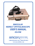
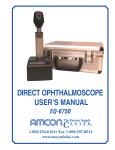
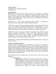
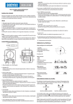
SLIT LAMP
USER’S MANUAL
EQ-6700
1-800-255-6161• Fax 1-800-397-0013
www.amconlabs.com
CONTENTS
Disclaimer and General Safety Warnings............................................................................. 2
Nomenclature.......................................................................................................................... 3
Assembly................................................................................................................................. 5
Components........................................................................................................................ 6
Assembly Procedure ........................................................................................................... 7
Checking Procedure After Assembling.............................................................................. 10
Operation Procedures .......................................................................................................... 11
Diopter Compensation and Pupil Distance Adjustment ..................................................... 11
Patient Position and Fixation Target ................................................................................. 12
Base Operation ................................................................................................................. 12
Changing the Aperture and Slit Height .............................................................................. 13
Maintenance.......................................................................................................................... 16
Replacing the Illumination Bulb ......................................................................................... 16
Replacing the Reflecting Mirror ......................................................................................... 16
Replacing the Fuse ........................................................................................................... 17
Replacing the Chin Rest Paper ......................................................................................... 17
Adjusting the Tightness of the Slit Width Knob.................................................................. 17
Adjusting the Inclination of the Illumination Part................................................................ 17
Cleaning ............................................................................................................................ 17
Protecting .......................................................................................................................... 18
Troubleshooting Guide ........................................................................................................ 19
Transportation and Storage................................................................................................. 20
Specifications ....................................................................................................................... 20
Amcon Slit Lamp
__________________________________________________________________________________
DISCLAIMER
Amcon: The Eyecare Supply Center makes no representations or warranties, either expressed
or implied, with respect to the contents hereof and specifically disclaims any warranties,
merchantability or fitness for any particular purpose. Further, Amcon: The Eyecare Supply
Center reserves the right to revise this publication and to make changes from time to time in
the contents hereof without obligation of this company to notify any person of such revision or
changes.
NOTE: Neither Manufacturer nor distributor assumes any responsibility or liability for any
damages caused by negligence or ignorance of precautions in this manual.
GENERAL SAFETY WARNINGS
Follow the proceeding Warnings to avoid injury and damage to the slit lamp.
WARNINGS
1.
Avoid flammable or explosive environments, dust, or high temperatures. For indoor use
only. Keep the slit lamp clean and dry.
2.
Check that all wires are correctly and firmly connected before using. Ensure that the
instrument is well grounded.
3.
Pay attention to all the rated values of the electrical connecting terminal.
4.
Use only a fuse with the specifications and rated values stipulated by the product.
5.
Use the supplied power cable with this instrument.
6.
Do not touch the surface of the lens or prism with the hand or any hard object.
7.
Turn off the main power first before replacing the illumination bulb and fuse.
8.
To prevent the instrument from falling, it should be placed on a surface with an inclination
angle of less than 10°.
9.
Turn off the power and cover the instrument with a dust cover when not in use.
10. In case of a problem, please refer to the troubleshooting guide.
2
Amcon Slit Lamp
__________________________________________________________________________________
NOMENCLATURE
1. Joystick -- Incline joystick to move the instrument slightly on the horizontal surface and
rotate it to adjust the elevation of the microscope.
2. Base Locking Screw -- Locks the base when fastened.
3. Rail Cover -- Protects the rail surface.
4. Base -- Supports the microscope and the illumination arms with the joystick.
5. Work Table
6. Accessory Drawer -- Storage for the focusing test rod and other accessories.
7. Brightness Control Switch -- Controls three levels of illumination – H (high), N
(normal), and L (low). Avoid working continuously at the high setting as the service life
of the bulb will be shortened.
8. Main Power Switch
9. Pilot Lamp
10. Microscope Arm Locking Knob -- Locks the rotational movement of microscope arm.
11. Angle Mark Ring -- Marks the ring of the illumination arm (which relate to the long mark
of the microscope) that represents the angle of the two arms.
12. Chin Rest Elevation Adjustment Knob -- Rotating the knob adjusts the elevation of
the chin rest.
13. Location Roller -- When in the middle, it represents the included angle of 0° between
the microscope arm and the illumination arm. When moved to the right or left, the angle
is 10°.
14. Microscope and Illumination Arm Couple Bolt -- Fastening this bolt allows the
illumination arm and the microscope arm to move and rotate together. When loosened,
the illumination arm can be rotated separately.
15. Hruby Lens Guide Plate -- Can also be used as an assembly plate for the applanation
tonometer.
16. Breath Shield
17. Chin Rest
3
Amcon Slit Lamp
__________________________________________________________________________________
18. Magnification Selection Dial – Turn to select the desired of five different
magnifications of the microscope.
19. Prism Box – Separate to adjust pupillary distance.
20. 12.5x Eyepiece
21. Microscope Fixation Screw
22. Applanation Tonometer Mount – Optional Applanation Tonometer (EQ-6703) mounts
here (sold separately).
23. Horizontal Mark – This serves as a guide to ensure proper chin rest height for each
patient. The patient’s outer canthus should be level with this mark.
24. Forehead Strap
25. Diffusion Lens -- Used for enlarging illumination field
26. Lamp Cap
27. Slit Height and Aperture Display Window
28. Filter Selection Lever -- Switches before four filters.
29. Horizontal Mark -- When the patient’s lateral canthus is in line with this mark, the
elevation of the microscope is controlled by the joystick in the center position.
30. Fixation Target -- Two fixation targets are available, the diopter adjustment target and
the illuminated fixation spot.
31. Reflecting Mirror -- Both long and short reflecting mirrors are provided. The long
mirror is routinely used for most examination procedures. The short mirror is used
when the long mirror interferes with observation, such as during funduscopy.
32. Hruby Lens -- Used for observation of the fundus and the posterior segment of the
vitreous body.
33. Hruby Lens Holder
34. Centering Knob -- Loosening this knob allows the illumination light to be moved from
the center of the visual field for indirect retroillumination. Fastening the knob brings the
illumination light back to the center.
35. Slit Width Control Knob -- The slit width is adjustable within the rage from 0 to 9mm.
The marks on the left knob stand for the approximate width of the slit.
4
Amcon Slit Lamp
__________________________________________________________________________________
36. Illumination Inclination Lever -- Four 5° inclination stops are available, up to 20°.
Figure 1
ASSEMBLY
This section of the manual describes how to assemble the slit lamp. All parts should be taken
out of the packing case with great care before assembling.
5
Amcon Slit Lamp
__________________________________________________________________________________
Components
A
B
C
D
E
F
G
H
I
J
K
L
M
N
O
P
Q
R
S
T
U
V
W
X
Name
Illumination Part
Converging Binocular Tubes
Base Part
Heat Rest Part
Breath Shield
Work Table with Power Box
Rail Cover
Input Power Cable
Hruby Lens
Hruby Lens Guide Plate
Spare Main Illumination Bulb (BT-6705)
Chin Rest Paper (JZ-7902)
Focusing Test Rod
Protection Cap
Dust Proof Cover
Fixation Target
Spare Long Reflecting Mirror
Spare Short Reflecting Mirror
Brush
Spare Fuse
Phillips Screwdriver with Wood Handle
Large Optical Screwdriver
Small Optical Screwdriver
Wrench
Qty
1
1
1
1
1
1
2
1
1
1
2
1
1
2
1
1
1
1
1
2
1
1
1
1
Figure 2
6
Amcon Slit Lamp
__________________________________________________________________________________
Assembly Procedure
Necessary tools for assembly: Phillips Screwdriver with wood handle (U), Optical Screwdriver
(V, W), and Wrench (X)
Selecting Voltage and Fuse
Check the setting on the voltage selector located on the bottom of the power box (Fig. 3). If it
does not match with the input voltage, slide it to the proper position with screwdriver (V). Open
the fuse holder with screwdriver (U) and take out the fuse. Ensure that its rated value is
corresponding to the mains voltage 220V, 0.5A. It has been set to 220v before leaving the
factory.
Figure 3
ATTENTION! Set the input voltage and frequency according to that of the mains.
Attaching the Worktable (F)
To attach the work table onto a motorized work table or exam lane arm, please screw off four
8x20mm bolts with spring washers using the wrench (X). Lift the work table to aim its screw
hold at the assembly hole of the instrument table. Put down the work table with the power
panel facing the operator, and then refasten the bolts securely with wrench.
Assembling the Head Rest (D)
Remove four screws attached to the chin rest connection board with the screwdriver (U). Put
two cables in the cap between the head rest fixation plate and the chin rest connection board
(Fig. 4). While ensuring that they are not clamped, retighten the previously removed screws.
Figure 4
7
Amcon Slit Lamp
__________________________________________________________________________________
Assembling the Base Part (C) and the Rail Covers (G)
Place the wheels of both sides of the base (C) on the rail on the work table. Check whether
the wheels can be rolled steadily on the rail. Remove four screws attached to the rail with the
screwdriver (U). Place the rail cover (G) to the rail; retighten the previously removed screws.
Assembling Illumination Part (A)
Loosen the illumination arm couple bolt (14). Rotate the brass shaft sleeve to make an
approximate angle of 30-90° between the red mark and the limiting board (Fig. 5).
Figure 5
Loosen the set screws in the illumination arm with the screwdriver (V). Aim the assembly hold
of the illumination arm at the brass shaft sleeve with care, and then put it down. Keep the
shaft close to the bottom surface well and simultaneously stretch the two red marks to one line.
After the two red marks are accurately aligned, retighten the set screws (Fig. 6).
Figure 6
8
Amcon Slit Lamp
__________________________________________________________________________________
Assembling the Microscope (B)
Match the groove on the binocular tubes with the pin on the microscope body (Fig. 7). Fasten
the fixation screw with the big screwdriver to fix the microscope.
Figure 7
ATTENTION! Avoid touching any lens surface.
Assembling the Breath Shield (E)
Remove the breath shield fixation screw from the microscope arm. Pass the removed screw
through the hold of the breath shield then rescrew it into the arm.
Connecting the Plug
Peel off the tape attached to the lamp cap, which ensures that the cap is tightened to the lamp
base during shipping. Insert the plug on the top of the head rest part (D) into the socket of the
lamp cap (26) on the illumination part (A). Connect the two plugs below the head rest part with
the corresponding output socket of the power box. Insert the plug of the input power cable (H)
into the input socket of the power box. Remove the cable clips from the bottom of the work
table with screw driver (U) and wrap the output and input cables respectively, then reattach
then to the bottom of the work table.
Assembling the Hruby Lens (I) and the Hruby Lens Guide Plate (J)
Insert the Hruby lens (I) into the Hruby lens holder (35) on the head rest. Be careful not to
touch the lens surface (Fig. 8). Place the Hruby lens guide plate (J) into the main shaft hold of
the base part with the small end pointing to the head rest.
9
Amcon Slit Lamp
__________________________________________________________________________________
Figure 8
Assembling the Chin Rest Paper (L)
Pull out the two fixing pins from the chin rest. Discard the paper package and allow the pins to
go through the holes. Insert the fixing pins into the hole again. Replacement chin rest papers
(JZ-7902) can be purchased from Amcon.
Storing Spare Parts
Some spare parts could be stored in the accessory drawer (6).
Checking Procedure After Assembling
Power Plug
This instrument supplies a three wire cable. Please select a proper power socket as matched.
Ensure that the instrument is well grounded.
ATTENTION! Please use the special cable supplied with this instrument.
Power Box and Illumination Part
When the main power switch (8) of the power box is placed at ‘I’, it turns on, and at ‘O’ it turns
off. The main power switch should be set at the ‘O’ position before connecting the input cable
with the power socket. Turn off the main power switch, and the pilot lamp (9) will be lighted.
Open the slit width control knob (35) to examine the illumination. Rotate the brightness control
switch (7) respectively at three positions and the brightness should be changed accordingly.
Check the fixation target device to confirm it is lighting. Check whether all the moveable parts
such as aperture and slit height control knob (29), filter selection lever (28), and magnification
lever (18) etc. could be operated freely. After examining, turn off the main power and cover
the instrument with the dust proof cover (O).
10
Amcon Slit Lamp
__________________________________________________________________________________
OPERATION PROCEDURES
Diopter Compensation and Pupil Distance Adjustment
Use of the Focusing Test Rod (M)
The rod is supplied as one of the standard accessories for confirming the microscope’s
accurate adjustment. Insert it into the main shaft hold with the flat surface facing the objective
lens, the direction of the operator (Fig. 9).
Figure 9
ATTENTION! After adjusting, remember to take out the rod and insert the protection
cap.
Brightness Adjustment
Switch on the main power switch and set the brightness control switch (7) at ‘N’ position. Turn
the slit width control knob (35) to make the slit width 2-3mm.
Diopter Compensation
The focus of the microscope is calibrated for an emmetropic user. If the operator has
uncorrected refractive error, the eyepiece should be adjusted to the proper power.
To adjust the eyepieces:
• Rotate the diopter adjustment ring (19) counterclockwise all the way.
• Rotate the ring clockwise until a sharp slit image appears on the focusing text
rod.
• Adjust the other eyepiece in the same manner.
• Record the diopter value on each eyepiece for future reference.
11
Amcon Slit Lamp
__________________________________________________________________________________
Pupil distance adjustment
Separate the prism box of the microscope with both hands to adjust the PD until both eyes can
see the same image on the focusing test rod through the eyepieces. A stereo view will be
seen.
ATTENTION! While adjusting the PD, ensure that both eyepieces are at the same
height.
Patient Position and Fixation Target
Positioning the Patient’s Head
Have the patient place his chin on the chin rest (17) and his forehead against the head rest
belt (24). Adjust the chin rest elevation adjustment knob (12) below the chin rest until the
patient’s canthus aligns with the horizontal mark (23).
Use of the Fixation Target
For fixing the patient’s eyesight, instruct him to look at the fixation target (30). To change fixing
position, move the lamp bar and move the curved lever around the forehead. The fixation
target with diopter compensation supplies a dot and concentric circles target. Slide the knob to
adjust the diopter compensation within the range of –15D to +10D. The fixation target with
spot light is used for the patient whose refractive error exceeds –15D. When changing, loosen
the fixation screw, replace the fixation target with the spot light source, and refasten with
fixation screw (Fig. 10).
Figure 10
Base Operation
Horizontal Rough Adjustment
Keep the joystick (1) erect and move the base (4) to make the microscope move on the
horizontal surface to aim at the object roughly (Fig. 11).
12
Amcon Slit Lamp
__________________________________________________________________________________
Figure 11
Vertical Adjustment
Rotate the joystick to adjust the microscope height until it aligns with the target. Turn the
joystick clockwise to raise the microscope and counterclockwise to lower it.
Horizontal Adjustment
Tilt the joystick to make the microscope move slightly on the horizontal surface. While looking
through the eyepieces, tilt the joystick to aim accurately at the object for a sharp image.
Locking the Base
When finishing the adjustment, fasten the base locking screw (2) to lock the base (4) to
prevent it from sliding.
Changing the Aperture and Slit Height
Changing the Slit Width
Turn the slit width control knob (35) and the slit width will be changed from 0 to 9mm. The slit
becomes a circle at 9mm. The approximate width is indicated by the scale on the knob.
Changing the Aperture and Slit Height
Turn the aperture and slit height control knob (29) and six different circular beams of light are
available at full aperture: 9, 8, 5, 3, 1, and 0.2 mm diameter. With a slit image, the slit height
can be changed continuously from 1mm to 9mm, which is indicated through the display
window (27).
Rotating the Slit Image
Swing the aperture and slit height control knob (29) horizontally to revolve the slit image at any
angle in the vertical or horizontal direction. The angle of image rotation is indicated by the
rotation angle scale with small division of 5° and big division of 10°.
Deflecting the Illumination Light
Loosen the centering knob (34) and swing the slit width control knob (35) back and forth so the
light spot moves away from the center of the microscope vision field. It is mainly used to
13
Amcon Slit Lamp
__________________________________________________________________________________
examine the eyes by indirect retroillumination. Fasten the centering knob and the slit light will
return to the center of the microscope vision field (Fig. 12).
Figure 12
Oblique Illumination
This is used for sectional or fundus examination by using a contact lens. Press down the
inclination lever (36) so that the illumination part inclines to 20° (5° of each division). Since the
illumination part may touch the patient’s head, operate carefully (Fig. 13).
Figure 13
Reflecting Mirror
Both short and long reflecting mirrors are included with this slit lamp. Use the long mirror in
normal examination. When the angle between the illumination part and the microscope is
within 3° to 10°, the examined imaged might be obstructed. In this case, use the short mirror.
The short mirror is also used when the illumination part is inclined over 10°.
14
Amcon Slit Lamp
__________________________________________________________________________________
Filter Selection
Turn the filter selection lever (28) in the horizontal surface to add four different kinds of filters
respectively into the illumination pathway. Usually the heat-absorbing filter is used so that the
patient may feel more comfortable during long periods of examination (Fig. 14).
Figure 14
Fundus Observation with Hruby Lens
During routine usage, observation with the slit lamp is limited within the range from the cornea
to the anterior portion of the vitreous body, owing to refraction effects of the cornea and the
crystalline lens. With the Hruby lens in front of the microscope, the posterior part of the
vitreous body and fundus then can be observed.
Examination Procedure with Hruby Lens:
1. The pupil should be dilated for approximately twenty minutes.
2. Insert the Hruby lens guide plate (15) into the main shaft hole of the illumination and
the microscope arm.
3. Pull out the Hruby lens holder from one side of the headrest. Move the Hruby lens
holder toward the operator so that it can slide freely to the left and right below the
chin rest. Insert the lower end of the Hruby lens lever into the groove on the guide
plate.
4. Move the focus of the illumination light and the microscope to the patient’s eye.
5. Move the lever to locate the Hruby lens at the center of the visual field and near the
patient’s eye.
6. Move the lever to focus the Hruby lens at the fundus, then adjust the slit height and
width to reduce the unnecessary light in the vision field.
15
Amcon Slit Lamp
__________________________________________________________________________________
7. To examine different views, either turn the microscope and the illumination arm or
change the patient’s fixation by manipulating the fixation target.
8. If the long mirror interferes in the examination, replace it with the short mirror.
9. After examination, move the Hruby lens back to the original position on one side of
the chin rest.
ATTENTION! Before moving the Hruby lens to the right and left, first have the
patient move his head away from the chin rest to avoid hitting the patient’s nose
with the Hruby lens.
MAINTENANCE
ATTENTION! The replaced waste materials should be treated as industrial waste.
Replacing the Illumination Bulb
Turn the main power switch (8) off. Pull out the plug connected to the lamp house. Rotate the
lamp cap (26) counter clockwise and pull it out from the illumination part (A). Take out the old
bulb and replace it. The groove in the bulb fixation disc should be aimed at the flange of the
lamp base; otherwise the illumination may be uneven (Fig. 15). Place the lamp cap in the
original position and rotate it clockwise. Then insert the connecting plugs. Turn on the main
power switch and assure that the new bulb works.
Figure 15
ATTENTION! The old bulb is hot.
Replacing the Reflecting Mirror
Set the angle between the microscope and the illumination arm to exceed 30°. Incline the
illumination arm by more than 10°. Remove the long mirror by holding the extended surface.
Insert a new long or short reflecting mirror. When replacing the short mirror, push the bottom
of the mirror by using an object with a sharp end (Fig. 16).
16
Amcon Slit Lamp
__________________________________________________________________________________
Figure 16
Replacing the Fuse
Turn off the main power switch (8) and pull out the input cable from the power socket. Screw
off the fuse holder cover with the screwdriver (X). Replace it with a new fuse and then fasten
the cover. The fuse specifications are as follows:
110V
1A, 250V
220v
0.5A, 250V
ATTENTION! Please select the fuse of the same type, specification, and rating.
Replacing Chin Rest Paper
When the paper needs replenished, pull upwards on the two fixing pins of the chin rest and
place a new package of paper. Then secure the fixing pins again.
Adjusting the Tightness of the Slit Width Knob
If the slit width control knob is too loose, the slit width may be out of control. Loosen the screw
on the right knob with the screwdriver (W), and then hold the left knob firmly with one hand,
while the other hand rotates the right knob clockwise to adjust its tightness. When it is
appropriate, fasten the screw of the right knob firmly again.
Adjusting the Inclination of the Illumination Part
If the inclination mechanism of the illumination part is too loose, fasten the screws on both
sides of the pivot point with the screwdriver (U).
Cleaning
1. Cleaning the lenses and mirrors
If any dust sticks on the lenses or reflecting mirrors, brush them with the brush (S)
supplied with the slit lamp. In case any dust still remains, wipe it off with a soft
cotton dipped with absolute alcohol.
ATTENTION! Never scratch with fingers or any other hard materials.
17
Amcon Slit Lamp
__________________________________________________________________________________
2. Cleaning the slide plate, rail, and shaft
If the slide plate, rail, and shaft are dirty, the vertical and horizontal movement will be
unsteady. Wipe them with a clean soft cloth.
3. Cleaning and sterilizing plastic parts
Clean the plastic parts such as chin rest bracket, headrest belt, etc. with a soft cloth
dipped in a soluble detergent or water. Sterilize with medicinal alcohol.
ATTENTION! Do not wipe with any corrosive detergent or the surface may be
damaged.
Protecting
Dust will settle into the main shaft hole of the illumination arm during operation unless
the hole is covered. Please cover the main shaft hole with the protection cap in order to
keep the instrument clean. Remove the cap when the guide plate needs to be
assembled (Fig. 17).
Figure 17
18
Amcon Slit Lamp
__________________________________________________________________________________
TROUBLESHOOTING GUIDE
In case of a problem with the slit lamp, please consult the following guide. If it still does not
work, contact an authorized repairperson.
Problem
Solution
Page
Connect the power
cable correctly.
10
Place the switch on
‘I’ position.
10
The plug on the power
box is loose.
Insert the plug firmly.
10
The plug on the lamp
cap is loose.
Insert the plug firmly.
9
The bulb has burnt out.
Change the bulb.
16
The fuse has blown.
Change the fuse.
17
The bulb is not
assembled properly.
Assemble the bulb
properly.
16
Set the filter lever to
the correct position.
15
Set the voltage
selector correctly.
7
The reflecting mirror
coating is oxidized.
Change the reflecting
mirror.
16
Too much dust is on
the reflecting surface.
Clean the surface
with the brush.
17
Voltage selector is
wrongly set.
Set the voltage
selector properly.
7
The fuse doesn’t match
specifications.
Replace it with
the proper fuse.
17
Slit Closes
Automatically
The slit width control
knob is too loose.
Adjust the tightness
of the control knob.
17
Fixation Target is Off
The output plug is
loose.
Insert the output plug
firmly.
10
No Illumination
Slit is Too Dark
Fuse has Blown
Possible Cause
The cable is not
connected correctly
with the power socket.
The main power switch
is on ‘O’ position.
The filter lever is in the
middle or in the
grey filter position.
Voltage selector is
wrongly set.
19
Amcon Slit Lamp
__________________________________________________________________________________
TRANSPORTATION AND STORAGE
During the transportation of the slit lamp, be careful to protect it from liquids, avoid vibrations,
and do not turn it upside down. The relative humidity should be 10% to 90% and the
environment temperature should be -25°C to 40°C.
This instrument should be stored in a well-ventilated room without corrosive gas. The relative
humidity should be 10% to 80% and the environment temperature should be -10°C to 40°C. If
the assembled instrument should be moved or transported a short distance, ensure that all
movable parts are locked. Move this instrument carefully by carrying on it table. If long
transportation is required, the slit lamp should be repacked in the original packaging.
SPECIFICATIONS
Microscope_________________________________________________________________
Type
Parallel Optics
Model of Magnifying
5 Steps by Drum Rotation
Eyepiece
12.5x
Total Magnification Rate
6x
Ø33mm
10x
Ø22.5mm
16x
Ø14mm
25x
Ø8.8mm
40x
Ø5.5mm
Range of PD Adjustment 55mm to 75mm
Diopter Adjustment
-5D to +3D
Illumination_________________________________________________________________
Slit Projection Magnification
2/3x
Slit Width
Continuous from 0mm to 9mm
(at 9mm, slit becomes circle)
Slit Height
∅9mm, ∅8mm, ∅5mm, ∅3mm, ∅2mm, ∅1mm, ∅0.2mm
Slit Angle
0° to 180° continuously, adjustable from vertical to horizontal
Slit Inclination
5°, 10°, 15°, 20° in four steps
Filters
Heat-absorbing, Grey, Red-free, Blue
Illumination Bulb
12V / 30W halogen bulb (BT-6705 from Amcon)
20
Amcon Slit Lamp
__________________________________________________________________________________
Movement Base_____________________________________________________________
Longitudinal Movement
90mm
Lateral Movement
100mm
Fine Base Movement
15mm
Vertical Movement
30mm
Chin Rest___________________________________________________________________
Vertical Movement
80mm
Fixation Target
Red LED
Hruby Lens_________________________________________________________________
Hruby Lens
-58.7D
Power Source_______________________________________________________________
Input Voltage
100/220V ~ ± 10%
Input Frequency
50/60 Hz
Power Consumption
58 VA
Output Voltage
Illumination Bulb
Fixation Target
Electric Safety Standard
Conforms to Standard IEC601-1, Class I Type B
7.2v, 9.8V, 11.6V
7.2V
Dimension and Weight________________________________________________________
Packing Box
720mm x 495mm x 480mm
Total Weight
24 kg
Net Weight
21 kg
Subject to change in design or specifications without advance notice.
21