1
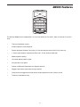
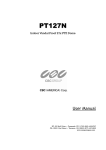
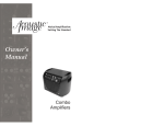
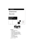
dB
500a
500 Watt 2-way Loudspeaker
A
U
D
I
O
SOUND REINFORCEMENT
dB500
Safety Instructions
Caution: To reduce the hazard of electrical shock, do not
remove cover or back.
No user serviceable parts inside. Please refer all servicing
to qualified personnel.
CAUTION
FOR CONTINUED PROTECTION AGAINST RISK
OF FIRE, REPLACE ONLY WITH SAME TYPE FUSE
ATTENTION
UTILISER UN FUSIBLE DE
RECHANGE DE MÊME TYPE
WARNING
DO NOT EXPOSE THIS EQUIPMENT
TO RAIN OR MOISTURE
AVIS
RISQUE DE CHOC ELECTRONIQUE
NE PAS OUVRIR
RISK OF ELECTRIC SHOCK
DO NOT OPEN
WARNING: To reduce the risk of fire or electric shock, do not expose this unit to rain or moisture.
The lightning flash with an arrowhead symbol within an equilateral triangle, is intended to alert the user to the
presence of uninsulated "dangerous voltage" within the products enclosure that may be of sufficient magnitude to
constitute a risk of electric shock to persons.
The exclamation point within an equilateral triangle is intended to alert the user to the presence of important operating and maintenance (servicing) instructions in the literature accompanying the product.
Important Safety Instructions
1.
Please read all instructions before operating the unit.
2.
Keep these instructions for future reference.
3.
Please heed all safety warnings.
4.
Follow manufacturers instructions.
5.
Do not use this unit near water or moisture.
6.
Clean only with a damp cloth.
7.
Do not block any of the ventilation openings. Install in accordance with the manufacturers instructions.
8.
Do not install near any heat sources such as radiators, heat registers, stoves, or other apparatus
(including amplifiers) that produce heat.
9.
Do not defeat the safety purpose of the polarized or grounding-type plug. A polarized plug has two
blades with one wider than the other. A grounding type plug has two blades and a third grounding
prong. The wide blade or third prong is provided for your safety. When the provided plug does not fit
your outlet, consult an electrician for replacement of the obsolete outlet.
10.
Protect the power cord from being walked on and pinched particularly at plugs, convenience receptacles and at the point at which they exit from the unit.
11.
Unplug this unit during lightning storms or when unused for long periods of time.
12.
Refer all servicing to qualified personnel. Servicing is required when the unit has been damaged in any
way, such as power supply cord or plug damage, or if liquid has been spilled or objects have fallen into
the unit, the unit has been exposed to rain or moisture, does not operate normally, or has been
dropped.
Table of Contents
Introduction
2
dB500Features
3
dB500 Components
4
Quick Set-Up
5
Controls and Functions
Positioning the dB500
Setting up your dB500
6
7-9
dB500 Wiring Guide
10
Specifications
11
Copyright 2001, Samson Technologies Corp.
Printed June, 2002
Samson Technologies Corp.
575 Underhill Blvd.
P.O. Box 9031
Syosset, NY 11791-9031
Phone: 1-800-3-SAMSON (1-800-372-6766)
Fax: 516-364-3888
www.samsontech.com
Introduction
Congratulations on purchasing the Samson dB500! The dB500 speaker system by Samson takes the concept of
PA systems to a new level. By combining 500 watts of power handling, advanced crossover design and the highest quality speaker and cabinet components, the dB500 provides studio quality sound for any kind of live application. The monitor features a super heavy-duty, custom designed, 15" Celestion® low frequency driver and a 1.75
inch (44 millimeter) titanium diaphragm high frequency driver on a 1" throat, wide dispersion horn. The dB500
offers crystal-clear audio and an ultra-wide sound field. The top end is clean, smooth and vivid. Not only a frontfiring PA speaker, the dB500’s are also designed to operate as wedge-style monitors. The cabinet’s right and left
side panels are joined at different angles, so depending on the side you choose, you get a different dispersion
angle, allowing for greater flexibility on stage. Adding to the dB500’s practical design is a catalog of mounting
options. The compact cabinet can be easily stacked, permanently installed, mounted using the integral 1 3/8"
pole mount receptacle or suspended using the ten built-in fly points. With the dB500, setup and break down is
quick and easy. Heavy-grade steel grills, scuff-resistant textured finishes and rigid corners offer excellent protection against wear and tear. As fixed sound reinforcement or as a durable, great-sounding road PA, the dB500
monitor is ideal for sound professionals and performers looking for serious output and studio monitor sound quality from a PA speaker system.
In these pages, you’ll find a detailed description of the features of the dB500 PA system, as well as a description
of its front and rear panels, step-by-step instructions for its setup and use, and full specifications. You’ll also find a
warranty card enclosed—please don’t forget to fill it out and mail it in so that you can receive online technical support and so we can send you updated information about these and other Samson products in the future.
With proper care your dB500 will operate trouble free for many years. We recommend you record your serial
number in the space provided below for future reference.
Serial number:
Date of purchase:
Should your unit ever require servicing, a Return Authorization number (RA) must be obtained before shipping
your unit to Samson. Without this number, the unit will not be accepted. Please call Samson at 1-800-3SAMSON
(1-800-372-6766) for a Return Authorization number prior to shipping your unit. Please retain the original packing
materials and if possible, return the unit in the original carton and packing materials.
2
dB500 Features
dB
500a
The Samson dB500 two way loudspeaker is an all-in-one solution for live sound. Here are some of its main features:
•
Two-way loudspeaker system.
•
Standard speaker stand receptacle.
•
Custom designed, Celestion, heavy-duty, 15-inch low frequency driver with 2.5-inch voice coil.
•
1" throat, high-frequency compression driver with 1.75-inch titanium diaphragm.
•
500 watt power handling .
•
15 and 30- degree monitor angles.
•
Arrayable with 10 fly points.
•
Internal 18 dB/octave Butterworth time aligned crossover.
•
Rugged, road-worthy construction for high reliability.
•
Quality build and rugged construction ensure reliable performance from venue to venue.
•
Three-year extended warranty.
3
dB500 Components
dB500 FRONT PANEL
1
2
3
15 Inch Driver – Custom designed
Celestion, heavy-duty, 15” low frequency
driver provides deep bass.
Wide Dispersion Horn – 1 inch throat,
60 x 90 degree wide dispersion horn provides extensive coverage and linear off
axis response.
Titanium Compression Driver – 1.75
inch (44mm), titanium diaphragm with 1
inch opening.
4
Handle – One of three ultra over sized
rubber grip carry handles.
5
Stacking Bumper – Gender mating
bumpers for stacking dB500’s.
6
Handle – One of three ultra over sized
rubber grip carry handles.
1
2
4
3
5
9
8
6
7
Active Monitor
dB
7
Steel Grill – Durable steel grill provide
protection for, and easy access to LF
driver.
8
Handle – One of three ultra over sized
rubber grip carry handles.
9
Enclosure – Rugged PVC plastic
enclosure.
500a
A
B
dB500 REAR PANEL
A
B
SPEAKER INPUT – Speakon connector for
connecting to power amplifier. See page
10 of this manual for a detailed wiring diagram.
WARNING: dB500 MONITOR CAN ACHIEVE
EXTREMELY HIGH SOUND PRESSURE
LEVELS. USE CAUTION OR HEARING
DAMAGE MAY RESULT.
FLYING HARDWARE FOR THE dB500 CAN
BE AFFIXED AT THE HANDLES,
REAR CABINET (2 POSITIONS)
AND TOP OF THE CABINET (2 POSITIONS).
FITTINGS ARE M8 (METRIC)
AND SHOULD BE EYE BOLTS
EXTENSION SPEAKER –1/4” parallel output for connecting additional dB500’s.
SPEAKER INPUT
SPEAKER
IN/EXTENTION
SIDE BY SIDE CONCERT ARRAY TOP VIEW
4
Quick Set-Up
In the following pages of this manual you will find a detailed explanation of system set-ups, but
if you just want to get started quickly you can follow the diagram and steps below to set up a
basic stereo PA system.
SPEAKER
INPUT
SPEAKER
INPUT
POWER AMP
OUTPUTS
POWER AMP
INPUTS
SERVO 550 STUDIO AMPLIFIER
CAUTION
SAMSON TECHNOLOGIES CORP., HICKSVILLE, NEW YORK
!
RISK OF ELECTRIC SHOCK
DO NOT OPEN
FUSE
FUSE
FUSE RATING
SERIAL
NUMBER
BRIDGED
MONO
STEREO
12A/250V (115V)
6A/250V (230V)
USE CLASS 2 WIRING MAXIMUM LOAD IMPEDANCE 4Ω
LEFT
CAUTION
HEATSINK MAY BE
HOT! DO NOT BLOCK
AIRFLOW OR OVERHEATING MAY OCCUR
RIGHT
TO PREVENT SHOCK DO
NOT OPEN. NO USER
SERVICABLE PARTS
INSIDE. REFER SERVICING
TO QUALIFIED SERVICE
PERSONNEL. TO PREVENT
FIRE OR SHOCK HAZARD
GROUND
+RIGHT
LEFT+
INPUTS
(BALANCED
10KΩ/0dBm0)
OUTPUT 250W/4Ω
TIP RING SLEEVE
RIGHT
TIP
+
RING
SLEEVE GND
~AC INPUT
115V/230W, 50/60HZ
510W (115V)900W (230V)
LEFT
MAIN LEFT AND RIGHT
OUTPUTS
MIC/LINE 1
MIC/LINE 2
MIC/LINE 3/4
MASTER SECTION
MIC/LINE 5/6
AUX OUT
LEFT/MONO
LEFT
LEFT
AUX RET
CR OUT
MIX OUT
RIGHT
RIGHT
RIGHT
SIGNAL FLOW
Active Monitor
dB
Active Monitor
500a
dB
30
3/L
30
GAIN
GAIN
CLIP
CLIP
5/L
LINE IN
LINE IN
500a
MONO OUT
SIGNAL FLOW
5
-26
+26
60
5
0
5
15
0
15
0
LF
0
15
15
LF
0
15
0
DYNAMIC
RANGE
5
2T IN
5 2.5K
2T OUT
10
15
LF
MAXIMUM
15
MF
5
10
5 80Hz
5
HF
12K
10
15
5 2.5K
10
5
10
MF
5
10
5 80Hz
5
0
5
12K
10
15
15
0
HF
5
10
5 2.5K
10
15
5
12K
15
MF
5
10
5 80Hz
5
0
HF
5
10
15
10
6/R
4/R
60
10
MF
5 2.5K
10
15
5
12K
10
0
5
+26
0
HF
5
10
15
-26
0
15
LEFT
RIGHT
LEFT
0
RIGHT
MONO 10
LF
5 80Hz
5
2TK TO MIX
10
10
15
15
10
10
15
15
AUX
10
10
15
15
AUX
10
5
10
15
48V
15
AUX
POWER
AUX
HARD
DISK
MODE
10
0
PEAK
+6
0
0
10
0
0
10
PAN
0
0
10
0
0
10
BAL
PAN
AUX RETURN
5
0
BAL
-6
-20
L
R
L
REC
10
R
L
10
10
10
5
5
0
0
5
5
5
5
0
0
5
5
10
10
10
10
15
15
15
15
20
20
20
20
30
40
30
40
30
40
30
40
5
0
5
_
_
_
_
_
_
_
_
CHANNEL 1
_
_
_
_
_
_
_
_
R
L
REC
REC
10
CHANNEL 2
R
10
0
MASTER SECTION
REC
10
10
MIX/2T
10
10
10
5
5
5
0
0
5
5
5
10
10
10
10
15
15
15
15
20
20
20
20
20
20
20
30
40
30
40
30
40
30
40
30
40
30
40
30
40
_
_
_
_
_
_
_
_
CHANNEL 3/4
_
_
_
_
_
_
_
_
5
10
0
CHANNEL 5/6
5
C/ROOM
+PHONES
5
0
10
0
5
_
_
_
_
_
_
_
_
0
_
_
_
_
_
_
_
_
0
5
5
10
10
10
15
15
15
PHONES
L
MIX
5
R
NOTE: It is important to remember the Golden Rule of audio … " LAST ON, FIRST OFF".
Translated, this means that when turning on your system, you should always turn your power
amplifiers or powered monitors on LAST, and when turning your system off, turn your power
amps off FIRST. This helps avoid any loud pops caused by inrush current at power up, which
can sometimes damage loudspeakers.
1
Before connecting your dB500’s, make sure that the power of all your systems components is turned off. Also, make sure that your power amplifier volume controls and the
main left and right faders of your mixer are turned all the way down.
2
Connect the cables to your microphones and instruments, or a CD player, to your mixer.
3
Switch on the power of the mixer, instruments and/or CD player, and then switch on
your power amplifier.
4
While speaking into the mic (or playing the instrument or CD), raise the mixers main
Left and Right faders to the "0" position. Be sure that the mixer’s output meters are not
clipping. If they are, adjust the mixer volumes down until the signal cleans up.
5
Now, slowly raise your power amp until you reach the desired listening level.
5
Controls and Functions
Positioning the dB500
Microphone Positioning - How to Reduce Feedback
Feedback is the annoying howling and squealing that is heard when the
microphone gets too close to the speaker and the volume is high. You get
feedback when the microphone picks up the amplified signal from the
speaker, and then amplifies through the speaker again, and then picks it
up again, and so on and so on. In general, it is always recommended that
any LIVE mic (a mic that’s on) is positioned behind the speaker enclosures. This will give you the best level from your system before feedback.
One possible exception is when you are adjusting the sounds of the
microphones, since you want to listen in front of the speaker to hear properly. To do this, lower the MAIN VOLUME while setting the EQ and effect
from in front of the speakers. Once you have the sound you like, move
the microphones to behind the speakers and raise the Main volume.
Active Monitor
Active Monitor
dB
dB
500a
500a
Speaker Placement
Whenever possible it is a good idea to raise the speakers above the
heads of the listening audience. The dB500 enclosure features a standard 1 3/8” pole mount receptacle, which are compatible with speaker
stands from a variety of manufacturers. In a smaller setting like a school
cafeteria, library, or a mall kiosk, you can also use the dB500 in one of
the tilt back monitor positions, which will improve the projection of the
speakers and may eliminate the need for speaker stands.
Using the dB500 as a Floor Monitor
The dB500 is an ideal solution for stage
monitoring and thanks to its unique design,
two wedge monitor positions are possible.
When placed on its side with the high frequency horn facing to the left of the enclosure, the dB500 is tilted at a 15 degree
angle optimizing performance when used
on a small stage. When placed on its side
with the high frequency horn facing to the
right of the enclosure, the dB500 is tilted at
a 30 degree angle optimizing performance
when used on larger stages. In a large
stage monitor system, several dB500’s can
be daisy-chained together using the
EXTENSION SPEAKER output.
FAR FIELD
Bottom
NEAR FIELD
Top
Note: Be sure to check the manufacturers
minimum recommended impedance for
STAGE MONITOR POSITION
STAGE MONITOR POSITION
15 DEGREES
30 DEGREES
your power amplifier to avoid overload and
possible damage to both the speaker and
amplifier. In many instances when using the dB500 as a monitor system, you may choose to use an
external equalizer like the Samson S Curve 131 to increase the volume and reduce the chance of
feedback.
6
500a
7
5
5
HF
12K
LF
5
5
5
5
N
21
R
0
5
0
5
REC
0
0
0
0
+26
_
_
_
_
_
_
_
_
-26
HF
12K
LF
R
30
40
20
15
10
5
0
5
10
PAN
10
AUX
15
10
5 80Hz
15
10
5 2.5K
MF
10
15
5
60
CHANNEL 2
30
40
20
15
30
40
CHANNEL 1
10
15
20
10
15
30
40
10
20
0
5
_
_
_
_
_
_
_
_
5
L
0
15
10
15
10
15
10
5
5
10
R
PAN
10
AUX
15
10
5 80Hz
15
10
5 2.5K
MF
10
15
5
10
REC
0
0
0
0
60
5
5
_
_
_
_
_
_
_
_
REC
0
0
0
0
LINE IN
HF
12K
LF
R
30
40
20
15
10
5
0
5
10
BAL
10
AUX
15
10
5 80Hz
15
10
5 2.5K
MF
10
15
5
CHANNEL 3/4
30
40
20
15
10
5
0
5
10
L
0
15
10
15
10
15
10
5
4/R
3/L
MIC/LINE 3/4
Lead Guitar
5
5
_
_
_
_
_
_
_
_
REC
0
0
0
0
LINE IN
HF
12K
LF
R
30
40
20
15
10
5
0
5
10
BAL
10
AUX
15
10
5 80Hz
15
10
5 2.5K
MF
10
15
5
CHANNEL 5/6
30
40
20
15
10
5
0
5
10
L
0
15
10
15
10
15
10
5
6/R
5/L
MIC/LINE 5/6
RIGHT
RIGHT
0
10
MIX/2T
10
10
PHONES
0
5
C/ROOM
+PHONES
0
5
HARD
DISK
LEFT
48V
RIGHT
2T OUT
DYNAMIC
10
LEFT
30
40
CAUTION
DO NOT OPEN
RISK OF ELECTRIC SHOCK
0
-6
MONO 10
~AC INPUT
115V/230W, 50/60HZ
SERVO 550 STUDIO AMPLIFIER
SAMSON TECHNOLOGIES CORP., HICKSVILLE, NEW YORK
SIGNAL FLOW
SIGNAL FLOW
Keyboards
Stereo Signal
MAIN POWER AMP
INPUTS
LEFT+
!
510W (115V)900W (230V)
SIGNAL FLOW
R
30
40
20
15
10
5
0
5
10
POWER
_
_
_
_
_
_
_
_
0
5
GROUND
OUTPUT 250W/4Ω
+RIGHT
MONO OUT
AUX OUT
RIGHT
FIRE OR SHOCK HAZARD
+6
MIX
20
30
40
15
20
10
5
0
5
SERVICABLE PARTS
INSIDE. REFER SERVICING
TO QUALIFIED SERVICE
PERSONNEL. TO PREVENT
-20
10
L
_
_
_
_
_
_
_
_
CAUTION
HEATSINK MAY BE
AIRFLOW OR OVER-
HOT! DO NOT BLOCK
HEATING MAY OCCUR
PEAK
15
5
0
5
10
SERIAL
NUMBER
USE CLASS 2 WIRING MAXIMUM LOAD IMPEDANCE 4Ω
TO PREVENT SHOCK DO
NOT OPEN. NO USER
RANGE
MASTER SECTION
RIGHT
AUX RETURN
5
2TK TO MIX
LEFT
2T IN
MAXIMUM
MIX OUT
CR OUT
AUX RET
RIGHT
LEFT
LEFT
MASTER SECTION
LEFT/MONO
Signal Processor
MODE
10
L
0
15
10
15
10
15
10
5
+26
CLIP
CLIP
5
GAIN
GAIN
-26
30
30
SIGNAL FLOW
MIC/LINE 2
SIGNAL FLOW
MIC/LINE 1
SIGNAL FLOW
STEREO
LEFT
RIGHT
RIGHT
LEFT
FIRE OR SHOCK HAZARD
PERSONNEL. TO PREVENT
TO QUALIFIED SERVICE
INSIDE. REFER SERVICING
SERVICABLE PARTS
NOT OPEN. NO USER
TO PREVENT SHOCK DO
HEATING MAY OCCUR
AIRFLOW OR OVER-
HOT! DO NOT BLOCK
HEATSINK MAY BE
CAUTION
SERIAL
NUMBER
CAUTION
DO NOT OPEN
RISK OF ELECTRIC SHOCK
GROUND
!
LEFT+
510W (115V)900W (230V)
115V/230W, 50/60HZ
~AC INPUT
OUTPUT 250W/4Ω
+RIGHT
USE CLASS 2 WIRING MAXIMUM LOAD IMPEDANCE 4Ω
6A/250V (230V)
12A/250V (115V)
FUSE
FUSE RATING
500a
SAMSON TECHNOLOGIES CORP., HICKSVILLE, NEW YORK
500a
dB
Active Monitor
dB
Active Monitor
STEREO
LEFT
RIGHT
TIP
+
RING
SLEEVE GND
TIP RING SLEEVE
10KΩ/0dBm0)
(BALANCED
INPUTS
BRIDGED
MONO
SPEAKER
INPUT
EXTENSION SPEAKER
OUTPUT
SPEAKER
INPUT
SERVO 550 STUDIO AMPLIFIER
MONITOR AMP
INPUT
SIGNAL FLOW
TIP
+
RING
SLEEVE GND
TIP RING SLEEVE
10KΩ/0dBm0)
(BALANCED
INPUTS
BRIDGED
MONO
SIGNAL FLOW
This example shows a typical PA system using mixer with an external power amplifier and a pair of dB500 for the main left and right
mix. A separate signal from the mixer’s AUX/MOINITOR buss is sent to two additional dB500’s place in the tilt-back, wedge positions
for use as floor monitors. In order to increase the output of the monitor system, the use of an external graphic equalizer like one of the
Samson “E” or “S curve” series is highly recommended.
500a
dB
dB
Bass Guitar
S direct
Direct Box
SIGNAL FLOW
SPEAKER
INPUT
Active Monitor
Active Monitor
Vocal
SA
M
SO
6A/250V (230V)
12A/250V (115V)
FUSE
FUSE RATING
FUSE
FUSE
SPEAKER
INPUT
Controls and Functions
Setting Up Your dB500 System
Controls and Functions
Setting Up Your dB500 System
Using Speaker Stands
The dB500 enclosure features a standard 1 3/8”,
pole mount receptacle, which are compatible with
speaker stands from a variety of manufacturers.
Before installing the dB500 on a speaker stand,
loosen the thumbscrew located on the bottom of the
rear side of the enclosure. Once installed on the
stand, be sure to tighten the thumbscrew to hold the
speaker in place. Be careful not to over tighten the
thumbscrew to avoid stripping the threads.
Stacking the dB500
The dB500 enclosure incorporates gender mating
stack feet and bumpers that allows you to stack one
dB500 on top of another. When stacking the
dB500’s, be certain that the rubber feet from the top
unit are securely fastened into the bottom unit’s
stacking bumpers.
NOTE: DO NOT STACK dB500’s OVER TWO (2)
TALL.
8
Controls and Functions
Setting Up Your dB500 System
Permanent Installation
The dB500 is logical solution for many
fixed installations in live sound venues,
discos, schools, houses of worship, convention centers and airport terminals to
name a few. The enclosure is extremely
versatile for installation as it can be hung
in several different positions by using the
10 Fly-points. Hanging the dB500 is serious business and therefore licensed and
insured professional sound contractors
only should perform such an installation.
Using the Fly-points
1
2
3
IMPORTANT NOTE: Only
10
5
WARNING: dB500 MONITOR CAN ACHIEVE
EXTREMELY HIGH SOUND PRESSURE
LEVELS. USE CAUTION OR HEARING
DAMAGE MAY RESULT.
FLYING HARDWARE FOR THE dB500 CAN
BE AFFIXED AT THE HANDLES,
REAR CABINET (2 POSITIONS)
AND TOP OF THE CABINET (2 POSITIONS).
FITTINGS ARE M8 (METRIC)
AND SHOULD BE EYE BOLTS
SPEAKER
IN/EXTENTION
SPEAKER INPUT
SIDE BY SIDE CONCERT ARRAY TOP VIEW
6
9
INTEGRAL STACKING FEATURE FOR PLACING
UNITS ON TOP OF EACH OTHER
MOUNTING FLY POINTS
FAR FIELD
NEAR FIELD
STAGE MONITOR POSITION
15 DEGREES
STAGE MONITOR POSITION
30 DEGREES
14.80 dB, 5060Hz
(171),0.000 msec (1)
110
LOG FREQUENCY - Hz
100
dB
SPL
90
80
70
60
20
50 100 200 500 1K 2K
5K 10K 20K
dB
15.0
10.0
5.0
0.0
-5.0
100.0
0.00
0.79
1.63
2.43
3.27
4.06 msec
10000.0
SPECTRAL DECAY
1000.0
FREQUENCY (Hz)
FREQUENCY RESPONSE
POLE MOUNT
110
SPEAKON WIRING
100
-
90
80
+
dB
SPL
1-
1+
70
+
The dB500 features ten Fly-points
located in pairs below each of the
five carry handles. By removing the
handles you will have access to the
threaded inserts that are compatible
with a variety of standard M8 hardware including that offered by ATM
Flyware.
4
60
20
50 100 200
CROSSOVER
500 1K
2K
5K 10K 20K
1 3/8"
35mm
2+
2-
1/4"
FREQUENCY (Hz)
MADE IN CHINA
licensed and insured professional
sound contractors should install the
dB500 using the Fly-points. Samson
assumes no liability for any installation.
S/N
DESIGNED AND ENGINEERED IN THE UNITED STATES BY SAMSON TECHNOLOGIES
www.samsontech.com
7
8
9
dB500 Wiring Guide
CONNECTING THE dB500
The dB500 provides both Speakon and 1/4” phone connectors for easy interface with industry standard cables.
You can use a variety of standard speaker cables that are available “off the shelve” at you local pro-audio or
musical instrument retailer. Be sure that cables use standard strained speaker wire, and a gauge 12-14 is recommended. If you are making you own cables, use the diagrams following below to ensure a proper hook up.
Unbalanced 1/4” Connector
Signal
Signal
Ground
Ground
Tip (signal)
Sleeve (ground)
Speakon Wiring Guide
SPEAKON™
+
1+
SPEAKON™
1-
2+
2-
NOT CONNECTED
10
dB500 Specifications
Power Rating: (@ 8Ω):
500 Watts Program
Frequency Response:
60 Hz – 15 kHz ± 3 dB
Operating Impedance:
8 Ohms
Sensitivity:
97 dB SPL @ 1W/1m
Crossover Frequency:
2.3 kHz (24 dB Per Octave)
LF Driver:
15″ heavy-duty driver
2.5″ voice coil (Kapton Former)
50 oz. barium ferrite magnet
HF Driver:
1.75" titanium compression driver
Mounting:
Integral 1 3/8″ Pole Mount Receptacle
15º wedge monitor position, 30º wedge monitor position, Ten Fly Points
Weight:
50 lbs.
22.7kg
Dimensions:
30″ (h) x 19″ (w) x 17″ (d)
(762mm) (h) x (483mm) (w) x (432mm) (d)
19″
(483mm)
17″
(432mm)
30″
(762mm)
dB
500a
19″
(483mm)
11
Samson Technologies Corp.
575 Underhill Blvd.
P.O. Box 9031
Syosset, NY 11791-9031
Phone: 1-800-3-SAMSON (1-800-372-6766)
Fax: 516-364-3888
www.samsontech.com