1
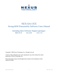
The Empeg and Riōcar
Memory Installation
and User’s Manual
Last Updated: 1 November 2004
Table of Contents
DISCLAIMER............................................................................................................................................................................................1
BEFORE YOU START............................................................................................................................................................................. 2
KIT CONTENTS....................................................................................................................................................................................... 2
TOOLS........................................................................................................................................................................................................2
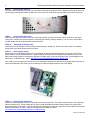
INTRODUCTION TO THE INSTALLATION PROCESS:................................................................................................................. 3
DOWNLOADING AND INSTALLING.................................................................................................................................................. 3
PLAYER DISASSEMBLY........................................................................................................................................................................4
..................................................................................................................................................................................................................... 4
INSTALLING THE MEMORY............................................................................................................................................................... 6
FINAL ASSEMBLY................................................................................................................................................................................ 16
1
The Empeg And Riōcar Memory Upgrade Installation and User’s Manual
READ THIS FIRST!!!
DISCLAIMER
Installation of this product requires that your Empeg Car or RiōCar be opened. Doing so will automatically void any
remaining warranty on the unit.
Please note that these kits require soldering surface mount integrated circuits. The level of soldering skill needed is
extremely high, and must not be attempted by a novice. Anyone who thinks that they can just pick up an iron from Radio
Shack and do this after five minutes practice is likely to kill their Empeg. If you are uncomfortable using the below tools, it
is highly recommended that you seek assistance from someone at ease with their use.
Please note that memory kits are not (currently) a product of Eutronix – this manual is simply provided as a resource for
the Empeg/RioCar community.
A Few Words about this Manual. . .
Every effort has been made to provide clear, easy to understand instructions to guide the user through the installation
process. We have included many high resolution images to facilitate the process. To get the most out of these images, it
is recommended that you print this manual in full color with a high quality photo or laser printer. It is intended that this
manual is printed double-sided. If printed single-sided, omit (blank) print pages numbers 2 and 4.
READ EVERY WORD OF THIS MANUAL BEFORE PROCEEDING WITH INSTALLATION. We hope you find the
installation process both straightforward and rewarding. It is advised that you go over the contents of the package to
ensure that there are no missing parts.
Limitation of Liability. Although every attempt has been made to avoid errors in the installation process, in no event and
under no legal theory, whether in tort (including negligence), contract, or otherwise, unless required by applicable law
(such as deliberate and grossly negligent acts) or agreed to in writing, shall Eutronix or any Contributor be liable to You for
damages, including any and all direct, indirect, special, incidental, or consequential damages of any character arising as a
result of this document, even if Eutronix or such Contributor has been advised of the possibility of such damages.
Eutronix provides this manual (and each Contributor provides its Contributions) on an "AS IS" BASIS. You are solely
responsible for determining the appropriateness of using this document. You assume all risk when installing the product.
The procedures depicted herein are merely provided as a guide to installation. What you decide to do is up to you.
E&OE
© Eutronix 2003-2004
The Empeg And Riōcar Memory Upgrade Installation and User’s Manual
2
Before you start
The URL (web address) for this document is http://www.eutronix.com/media/memory_manual.pdf. If you did not download
this document from the URL just provided, please enter the URL into a web browser and check that you have the latest
version of this document (check the Last Updated date on the front cover).
Kit contents
Empeg MK1 Memory Kits upgrade a MK1 player from 8MB to 16MB and contain:
§ 4 – Memory Chips (1Mx16 3.3v 1k refresh TSOP-44/50 EDO DRAM: Micron MT4LC1M16E5TG-5,
Siemens HYB3118165BST-60 or equivalent)
§ 2 – Feet Hookup (or enameled) wire
Empeg MK2 Memory Kits upgrade a MK2 player from 12MB to 16MB and contain:
§ 2 – Memory Chips (1Mx16 3.3v 1k refresh TSOP-44/50 EDO DRAM: Micron MT4LC1M16E5TG-5,
Siemens HYB3118165BST-60 or equivalent)
§ 2 – Feet Hookup (or enameled) Wire
RiōCar (MK2a) Memory Kits upgrade a MK2a player from 16MB to 32MB and contain:
§ 2 – Memory Chips (4Mx16 3.3v 4k refresh TSOP-50 EDO DRAM: Micron MT4LC4M16R6TG-5 or
equivalent)
§ 2 – Feet Hookup (or enameled) Wire
Not got a kit? At the time of writing, RiōCar (MK2a) memory kits were available from Paul Grzelak (send a private
message to pgrzelak via the BBS or mail pgrzelak at verizon.net), but Empeg MK1 and MK2 memory kits were not
available. BBS members scofiel or altman may be able to supply existing BBS members with memory chips for the
MK1/MK2. Check the “For Sale” section of the BBS (link above) for the latest information. Both memory chips are hard to
source now so you are unlikely to find them at places like Digikey, Mouser, Farnell or RS components.
Don’t have the skills to do the install yourself? Post a message on the BBS – there is probably a member near you that is
willing and able to install the kit for you for a small fee. Please contact an installer before ordering your kit if possible –
they may be able to obtain kits at a discounted price.
Tools
Please take a few moments to familiarize yourself with the installation process to avoid any potential pitfalls. A few things
you will need prior to installation:
§
§
§
§
§
§
§
§
§
§
§
§
§
§
§
§
§
2.5 mm hex wrench
Small tipped Phillips screwdriver
Medium tipped Phillips screwdriver
Small flat bladed screwdriver
Fine tip tweezers
Magnifying stand or microscope
A fine tipped variable temperature soldering iron with grounding point (or fixed temperature soldering iron 20 – 40
watts with grounding point)
Multimeter
Fine grade electronic solder, 60/40 or 63/37 rosin core should work fine
Solder flux (a no clean solution is recommended for least clean up)
Isopropyl alcohol
Hot melt glue gun with fine tip
Hijack kernel or software player release v2.01
Scalpel (X-Acto) knife with chisel blade (optional)
ESD station or ESD field mat with wrist strap and grounding connection to soldering iron
Plasticard (optional)
Glue stick (Prittstick)
© Eutronix 2003-2004
3
The Empeg And Riōcar Memory Upgrade Installation and User’s Manual
Introduction to the Installation Process:
The following portion of the manual assumes that you have obtained all necessary components for the memory upgrade.
If you have not purchased a complete kit or the necessary components, please see the component list on the preceding
page for the components necessary for your intended application.
Downloading and installing
STEP 1 – Downloading and installing the Kernel
You will need either player software version v2.01 or Mark Lord’s Hijack Kernel to make use of the extra memory
V2.01 METHOD
If you choose to go the vendor route, install the v2.01 kernel available at: http://www.empeg.com/v3alpha/car-v2.01/
according to the instructions at: http://www.empeg.com/v3alpha/car-v2.01/car-v2.01-notes.txt
HIJACK METHOD
If you choose the Hijack route, install Mark Lord’s Hijack kernel available at: http://empeg-hijack.sourceforge.net/
according to the instructions at:
http://www.riocar.org/modules.php?op=modload&name=FAQ&file=index&myfaq=yes&id_cat=11&categories=Hijack+Kern
el+Questions&faqent=177#177
STEP 2 – Installing Hyperterminal
If you have not already done so, install Hyperterminal according to the instructions at:
http://www.riocar.org/modules.php?op=modload&name=FAQ&file=index&myfaq=yes&id_cat=7&faqent=82#82
and confirm that you can receive diagnostics from the Empeg serial port using this software and a serial lead.
© Eutronix 2003-2004
The Empeg And Riōcar Memory Upgrade Installation and User’s Manual
4
Player Disassembly
STEP 1 – Removing power
Disconnect power from the player. Work in a static-free environment by grounding yourself prior to handling the kit parts
or any internal components of the player.
STEP 2 – Loosening the fascia
Locate the four hex bolts on the front of the player. Using a 2.5 mm hex wrench, carefully remove each bolt.
STEP 3 – Removing the fascia
Grasp the fascia piece by the edges and pull towards the front of the player.
STEP 4 – Removing the knob
Grasp the knob on the right side of the player and gently tug on it until it comes loose from the encoder shaft to which it is
mounted.
STEP 5 – Removing the buttons
Carefully remove the four buttons located on the left side of the player, putting them aside while keeping them oriented in
their installed position inside the player fascia.
STEP 6 – Removing the faceplate
Remove the faceplate piece by carefully pulling it away from the front of the player. Put it aside, face down in a safe place.
If your unit has a factory-installed faceplate, care should be taken not to damage the EMI coating on the backside of the
plate. Do not allow ANYTHING to come in contact with this coating, especially fingers.
If after removing the player faceplate you discover that any of the hex bolt sockets have come loose, tighten them before
proceeding.
If any of the hex bolt sockets have become completely separated from the display board. Locate the small lock washers
that mount between the hex bolt socket shaft and the display board. They may have fallen out of the player during the
disassembly process or may have become lodged inside the player. DO NOT PROCEED UNTIL YOU HAVE LOCATED
AND RESECURED ALL LOCK WASHERS ONTO THE DISPLAY BOARD.
STEP 7 – Removing the player lid
Remove the player lid:
§
Slide the lid forward towards the front of the player until the tabs of the lid meet up with the folded tabs on the body
of the player
§
Extend the handle on the front of the player all the way forward to remove the locking arms from the path of the lid
§
Locate a small flat bladed screwdriver and gently pry up on the lid in the location shown to pass the lid over the
obstruction in the case while sliding forward. Do this on both sides.
© Eutronix 2003-2004
5
The Empeg And Riōcar Memory Upgrade Installation and User’s Manual
STEP 8 – Releasing the drive tray
Once the player lid has been removed, you should have full access to the player interior. Begin by removing the drive tray
screws using a small tipped Phillips screwdriver to remove the four small screws (two per side) on the side of the player.
STEP 9 – Removing the drive cable
Slide the drive tray back, away from the front of the player and lift up to access the drive cable connector on the player
main board. Carefully remove the connector from the player board by pulling it straight up. Do not rock it side to side or
the IDE header pins on the player board may become bent.
STEP 10 – Removing the display cable
Carefully remove the connector from the player board by pulling it straight up. Do not rock it side to side or the display
header pins on the player board may become bent.
STEP 11 – Releasing the display
Remove the four small Phillips screws on the front sides of the player to release the display circuit board. Next, lift the
player handle to its fully extended position. Angle the display circuit board at a 45 degree angle towards the front of the
player and carefully maneuver it around any obstacle in its path until it is free from the player case. Put the display to one
side (keep in on the ESD mat). Movie: http://www.riocar.org/upload/faqpics/remove_display.mpg.
Also, while you are working on this, make sure not to damage the capacitors on the back of the display board, they can be
broken off accidentally. Also watch you do not damage or break the fragile fill nipple on the VFD display:
STEP 12 – Releasing the main board
Remove the three plugs that connect the docking socket to the main board. The small 4-way connector on the right-hand
side has a latching clip. Gently release the clip using a small flat bladed screwdriver while pulling out the plug (pull the
plugs themselves, not the wires). Undo the two hex nuts that hold the serial port in place, then remove the five screws that
hold the main board in its case. Finally, lift and slide the main board out. Movie:
http://www.riocar.org/upload/faqpics/remove_mainboard.mpg.
© Eutronix 2003-2004
The Empeg And Riōcar Memory Upgrade Installation and User’s Manual
6
Installing the Memory
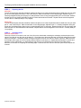
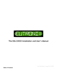
STEP 1 – Identifying the pins
Taking ESD precautions, remove the two integrated circuits from their protective packaging and identify pin one. Pin one
can normally be identified by a small dimple in the plastic packaging adjacent to the pin, as marked by a red dot in the
photographs below. Alternatively, the chip may have pimple adjacent to the pin or a notch at, or line across, one end.
These are also marked in red on the photos:
Figure: MK2A memory
MK1/MK2 memory
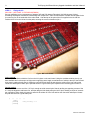
STEP 2 – Identifying the main board memory pads – MK1 ONLY
The pads for the memory ICs are located on the underside of the main board. Skip to step 5.
Figure: MK1 main board (after fitting of ICs)
© Eutronix 2003-2004
7
The Empeg And Riōcar Memory Upgrade Installation and User’s Manual
Identifying the main board ICs – MK2 AND MK2A ONLY
The two memory ICs are located closest to the StrongArm CPU. The CPU can be identified by the Empeg serial number
stuck on it, or the Arm or StrongArm logo, if the serial number is missing.
Figure: MK2 main board( after fitting of ICs)
Figure: MK2A main board
© Eutronix 2003-2004
The Empeg And Riōcar Memory Upgrade Installation and User’s Manual
8
STEP 3 – Preparing the ICs
MK2 ONLY
Turn the chip around so that the orientation matches the photo, then count the pins down the left hand side until you reach
pin 18 (count the gap as three pins) – this is the RAS pin. Make a small mark on the chip package, adjacent to pin 18.
Carefully straighten all the pins except pin 18 and bend them down so they are approximately 85% to horizontal. Beware
that the pins are very fragile and liable to break off if bent backwards and forwards. Repeat with the second integrated
circuit in the kit. Carefully bend pin 18 up slightly.
MK2A ONLY
Turn the chip around so that the orientation matches the photo, then count the pins down the left hand side until you reach
pin 14 – this is the RAS pin. Make a small mark on the chip package, adjacent to pin 14. Carefully straighten all the pins
except pin 14 and bend them down so they are approximately 85% to horizontal. Beware that the pins are very fragile and
liable to break off if bent backwards and forwards. Repeat with the second integrated circuit in the kit. Carefully bend pin
14 up slightly.
STEP 4 – Checking the fit
MK2 AND MK2A ONLY
Place one of the ICs from the kit over one of the ICs on the main board, matching the orientation so that the pins on the
upper IC are directly over the pins on the lower IC. Check that every pin except the bent up RAS pin makes good contact
with its counterpart. If necessary, adjust the angle of the pins on the IC from the kit to ensure a good fit. Make sure that
the RAS pin on the upper IC is not in contact with the RAS pin on the lower IC. Repeat with the second IC in the kit and
second IC on the main board. It is worth taking a long time to try for perfection on this step as it will make a huge
difference to the ease of competing the remaining steps. Place the ICs from the kit to one side (on the ESD mat) for the
moment.
© Eutronix 2003-2004
9
The Empeg And Riōcar Memory Upgrade Installation and User’s Manual
STEP 5 – Fitting the ICs
MK1 ONLY (SEE PAGE 11 FOR MK2 AND MK2A)
Set your soldering iron to a temperature of between 450 and 550 degrees Fahrenheit (240-280 degrees Celsius).
Exceeding 550 degrees Fahrenheit could damage the components. ‘Paint’ a small amount of solder onto the pads for the
four memory ICs on the underside of the main board. Coat the tips of the pins of the ICs supplied in the kit with flux.
Position the ICs from the kit back on the pads, ensuring the correct orientation of pin 1.
Figure: MK1 main board
Andym method:
Use a dab of Pritt-Stick to hold the ICs from the kit in place on the main board. Using the smallest soldering iron tip you
have available and a microscope or high-power magnifying stand, apply a small amount of solder to the tip of the iron and
then press it against the pin where it meets the pad until the pin heats up and wicks the solder off the iron and into the
connection whereupon it heats up the pad and results in a good solder joint. Repeat for the remaining pins on each IC.
Genixia method:
The blob of solder on the end of a 1/16" tip is enough to solder several pins. Start by tacking two opposing corners of the
IC. Verify the alignment, add more flux, and then drag the blob slowly along the line of pins, allowing a couple of seconds
per connection. When each pin heats up it will wick the solder off of the iron and into the connection whereupon it heats
the pad and results in a good solder joint.
||
|| || ||
(OOO)
[TTTTT]
[TTTTT]
||
Drag slowly --->
© Eutronix 2003-2004
The Empeg And Riōcar Memory Upgrade Installation and User’s Manual
10
The keys to this technique are flux and patience. If you don't allow enough time per pin then the solder won't wick properly
and you'll end up dragging a bridge of solder across all the pins. If you don't have enough flux then you will also bridge
adjoining connections. With a hundred connections to make it is likely that one or more bridges will be made anyway ('cos
we're not pro's). Clean all solder off of the iron, add flux to the bridged pins and reheat. Often this is enough to wick out the
bridge - the solder wicks back onto the iron. In stubborn cases where this doesn't work, fine desoldering braid will wick it
out (with flux, obviously). When this happens you'll need to repaint the connection and also a couple each side of it as the
braid isn't fine enough to only hit one connection.
This technique is used by many professionals to mount fine SMT chips to boards - they paint the pads and rely on the
wicking action to draw solder under the pin. In this way they avoid physical contact with pins that are easy to bend.
Allegedly they use the biggest tip size that they can get into the board as it holds the most solder.
© Eutronix 2003-2004
11
The Empeg And Riōcar Memory Upgrade Installation and User’s Manual
Fitting the ICs
MK2 AND MK2A ONLY
Set your soldering iron to a temperature of between 450 and 550 degrees Fahrenheit (240-280 degrees Celsius).
Exceeding 550 degrees Fahrenheit could damage the components. ‘Paint’ a small amount of solder onto the pins of the
two memory ICs on the main board. Coat both sides of the pins of the ICs supplied in the kit with flux. Place the ICs from
the kit back on top of the memory ICs on the main board.
Andym method:
Use a dab of Pritt-Stick to hold the ICs from the kit in place on top of the memory ICs on the main board. Using the
smallest soldering iron tip you have available and a microscope or high-power magnifying stand, apply a small amount of
solder to the tip of the iron and then press it against the pin until the solder flows off the tip and onto the pin of the chip.
Repeat for the remaining pins on each IC.
Genixia method:
The blob of solder on the end of a 1/16" tip is enough to solder several pins. Start by tacking two opposing corners of the
IC. Verify the alignment, add more flux, and then drag the blob slowly along the line of pins, allowing a couple of seconds
per connection. When each pin heats up it will wick solder off of the iron and into the connection whereupon it heats the
other pin and results in a good solder joint.
||
|| || ||
(OOO)
[TTTTT]
[TTTTT]
||
Drag slowly --->
The keys to this technique are flux and patience. If you don't allow enough time per pin then the solder won't wick properly
and you'll end up dragging a bridge of solder across all the pins. If you don't have enough flux then you will also bridge
adjoining connections. With a hundred connections to make it is likely that one or more bridges will be made anyway ('cos
we're not pro's). Clean all solder off of the iron, add flux to the bridged pins and reheat. Often this is enough to wick out the
bridge - the solder wicks back onto the iron. In stubborn cases where this doesn't work, fine desoldering braid will wick it
out (with flux, obviously). When this happens you'll need to repaint the connection and also a couple each side of it as the
braid isn't fine enough to only hit one connection.
This technique is used by many professionals to mount fine SMT chips to boards - they paint the pads and rely on the
wicking action to draw solder under the pin. In this way they avoid physical contact with pins that are easy to bend.
Allegedly they use the biggest tip size that they can get into the board as it holds the most solder.
STEP 6 – Test the connections
Using an ohmmeter, a milliohmmeter or multimeter set to resistance, probe each connection on each IC to check for 1)
continuity between top and bottom pins and 2) lack of continuity between adjacent pins. You’ll find it easier to use the
audible continuity setting on the meter, if available. Rework the solder to fix any open or bridged pins.
STEP 7 – Fitting the RAS line
MK2 ONLY
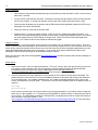
Starting at pin 105 in the bottom left-hand corner of the StrongArm CPU and working towards the right, count the pins until
you reach pin 121 (nRAS3), as indicated on the “MK2 main board” photo, above. Make a small mark on the package,
adjacent to pin 121. Solder the hookup wire between the bent-up RAS pin on each of the ICs from the kit and then on to
pin 121 of the StrongArm.
MK2A ONLY
Starting at pin 105 in the bottom left-hand corner of the StrongArm CPU and working towards the right, count the pins until
you reach pin 123 (nRAS1), as indicated on the “MK2A main board” photo, above. Make a small mark on the package,
adjacent to pin 123. Solder the hookup wire between the bent-up RAS pin on each of the ICs from the kit and then on to
pin 123 of the StrongArm.
© Eutronix 2003-2004
The Empeg And Riōcar Memory Upgrade Installation and User’s Manual
12
Figure: MK2 main board
Figure: MK2A main board
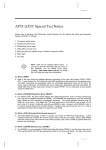
STEP 8 – Debug the error messages
Ensuring that the main board is resting on the resistive-dissipative (not the conductive side) of the ESD mat (or temporarily
popping the main board back in its case), connect up the serial port to the computer. Start up hyperterminal and connect it
to the serial port, then apply power to the Empeg. You should something like:
© Eutronix 2003-2004
13
The Empeg And Riōcar Memory Upgrade Installation and User’s Manual
c2000000: wrote ffffffff, read 00000000
NetWinder Floating Point Emulator V0.94.1 (c) 1998 Corel Computer Corp.
empeg-car player (hardware revision 9, serial number 10101626) 32MB DRAM
Command line: mem=16m
Calibrating delay loop... 207.67 BogoMIPS
Memory: 31240k/32M available (980k code, 20k reserved, 524k data, 4k init)
A message of “Checking for extra DRAM at c1000000: wrote 00000000, read c00e78e0” indicates either no extra DRAM
found or test failed on the extra DRAM. In either case, the player startup continues WITHOUT the extra DRAM being used.
Similar messages might appear on megabyte (0x100000) boundaries whenever the DRAM test finds a fault. The player is
"told about" all DRAM that passed the test. For instance "Checking for extra DRAM at c1300000: wrote 00000000, read
c00e78e0” would indicate that an extra 3MB passed, at which point an error was found. The player s/w will start up with
19MB total DRAM.
The memory test uses 4 patterns written across the data lines, 0x00000000, 0xFFFFFFFF, 0xAAAAAAAA, and
0x55555555.
0x00000000 - An error from this write is usually caused by a data pin shorted to an adjacent Vcc pin.
0xFFFFFFFF - An error from this write is caused either by a data pin shorted to an adjacent VSS pin or more usually by an
open connection.
0x55555555 and 0xAAAAAAAA are caused by two adjacent pins shorted together - the patterns translate to binary
0101...0101 and 1010...1010 respectively. What should be a zero comes back as a one because of the short.
The error message reports what was written and what was read. Compare one to the other and see where the error is.
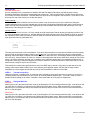
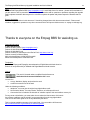
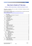
The highest 16 bits of the data are on the chip furthest from the CPU.
So for example, "wrote 0xFFFFFFFF, read 0xFFAFF1FF" on a MK2A can be broken down to;
Chip furthest from CPU - 0xFFAF. We can further break this down visually - 0xFF means that the high 8 bits are correct,
0xAF means that the lowest 4 bits are correct, and the problems are in DQ7...DQ4. 0xA is binary 1010, so the problem
pins are DQ6 and DQ4, both low when they should be high. Looking at the pin-out you will see that pins 7 and 9 are
probably open.
44/50-Pin TSOP
Figure: Memory Pin-Out for MK1 / MK2
50-Pin TSOP
Figure: Memory Pin-Out for MK2A
© Eutronix 2003-2004
The Empeg And Riōcar Memory Upgrade Installation and User’s Manual
14
Chip nearest CPU - 0xF1FF. Breaking it down again, lowest 8 bits are fine as are topmost 4 bits, problem is in
DQ11...DQ8. 0x1 is binary 0001. Pins DQ11, DQ10 and DQ9 are all low when they should be high. Looking at the pin-out
shows that pins 44, 43 and 42 are the culprits. You will also notice that pin 45 is VSS, so it's possible that one or more of
those pins are shorted together with pin 45. Or they might simply be open.
Another example, "wrote 0xAAAAAAAA, read 0xAAAAAAEA";
The problem is in lowest 16 bits, that is the chip nearest CPU, 0xAAEA. Further breaking it down, highest 8 bits and lowest
4 bits are fine, problem is in DQ7...DQ4.
Wrote 0xA = binary 1010. Read 0xE = binary 1110. Problem is DQ6 high when it should be low, shorted to either DQ7 or
DQ5. The pin-out gives DQ6 as pin 9. (DQ7= 10, DQ5 = 8)
There are three problems that won't fall into any of those error classes. A bad RAS connection or a bad OE connection
can both manifest as an error where the whole chip refuses to talk back
A totally non-booting Empeg, or one that crashes even after passing the memory test is usually caused by soldering errors
on the address lines. Some errors will prevent the flash from being read and hence the kernel can't load, whereas others
won't affect the player until the kernel attempts to use the memory space impacted.
Unfortunately it isn't possible to debug this further to individual pins.
Once you have decoded the error messages, unplug the power and serial port and rework the problem pins to remove
errors. Repeat steps 6 and 8 until everything is okay and you get text similar to:
c2000000: wrote ffffffff, read 00000000
NetWinder Floating Point Emulator V0.94.1 (c) 1998 Corel Computer Corp.
empeg-car player (hardware revision 9, serial number 10101626) 32MB DRAM
Command line: mem=16m
Calibrating delay loop... 207.67 BogoMIPS
Memory: 31240k/32M available (980k code, 20k reserved, 524k data, 4k init)
FOR INFORMATION – 48MB or 64MB on MK2A
It is possible to stack a third or even a fourth set of ICs on top to achieve 48 or 64MB memory respectively, however this is
definitely not recommended – this text is provided for information only.
48MB is approximately ten times harder to do than 32MB and you will almost certainly end up with at least one broken
RAS pin.
It is possible to hack away at the plastic packaging with a scalpel blade (X-acto knife) to get at the RAS line if this happens.
You will also have to modify the hard-drive mounts to lift the drive bay clear of the memory stack and you will need to
protect the RAS hook-up wires and pins from damage due to vibration somehow (perhaps by using hot-melt glue or fixing
a small piece of plasticard over the memory and wires).
You are probably best waiting for “pca” to produce a proper memory daughter board if you want 64MB RAM. If you really
want to do this, you connect the RAS pins from the third stack ICs to nRAS2 on the CPU (which is pin 122) and connect
the RAS pins from the fourth stack ICs to nRAS3 on the CPU (which is pin 121).
A successful 48MB boot-up looks like this:
C3000000: wrote ffffffff, read 00000000
NetWinder Floating Point Emulator V0.94.1 (c) 1998 Corel Computer Corp.
empeg-car player (hardware revision 9, serial number 10101600) 48MB DRAM
Command line: mem=16m
Calibrating delay loop... 207.67 BogoMIPS
Memory: 47462k/48M available (980k code, 20k reserved, 686k data, 4k init)
A successful 64MB boot-up looks like this:
c3f00000: passed.
NetWinder Floating Point Emulator V0.94.1 (c) 1998 Corel Computer Corp.
empeg-car player (hardware revision 9, serial number 10101663) 64MB DRAM
Command line: mem=16m
Calibrating delay loop... 207.67 BogoMIPS
Memory: 63684k/64M available (980k code, 20k reserved, 848k data, 4k init)
© Eutronix 2003-2004
15
The Empeg And Riōcar Memory Upgrade Installation and User’s Manual
It is theoretically possible to exceed 4MB per bank limit on the MK1 and MK2 (to give more than 16MB total) but the
procedure would be quite complex (altman, pca and mlord among others have discussed it on the BBS a couple of times).
No-one has tried (this means that even the electronics Gods on the BBS consider it too difficult to attempt). One possible
ray of hope for MK2 owners would be the 64MB memory daughter board mentioned above. It is also possible to exceed
the 64MB limit of the MK2A in theory – but would require some glue logic, there are problems with the memory refresh rate
to overcome and further modifications to the kernel would be required.
STEP 9 – Tidy up
Clean any excess flux from the components using Isopropyl alcohol. You may want to protect the RAS hook-up wires and
pins from damage due to vibration by melting a small amount of hot-melt glue over the pins and tacking the wires to the
board or IC package in a couple of places. If you have some thin plasticard available, you could cut a small rectangle to
cover the memory ICs and the wire run, using hot-melt glue to keep the card in place.
© Eutronix 2003-2004
The Empeg And Riōcar Memory Upgrade Installation and User’s Manual
16
Final Assembly
STEP 1 – Testing the memory – HIJACK ONLY
Before reassembling your player, test your installation work.
§
Connect the display board to the main board of the player. When connecting the display, be absolutely
certain that the connector is installed properly with no misaligned pins. If the connector is not properly
installed, you will blow a fuse on the player or worse. Be careful!
§
Power up the player.
§
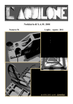
Once the player has started, go into the hijack menu (long-press the volume knob) and select “Vital Signs”
§
It should look something like this:
Figure: Hijack Vital Signs screen (MK2A)
STEP 2 – Reassembly
If all went well in the testing phase above, reassemble your player.
Internal Assembly
§
Reinstall the drive cable onto the main player board, being careful to maintain the same orientation as the
original installation. Make sure the pins are correctly aligned.
§
Secure the drive tray while assuring that each of the DIG-CXXXX output cables remains accessible (if
applicable) after securing.
§
The display cable should be installed from step 1 above.
© Eutronix 2003-2004
17
The Empeg And Riōcar Memory Upgrade Installation and User’s Manual
External Assembly
§
Fully extend the player handle and slide the player lid right side up so that the label is visible, over the locking
tabs until it is secured.
§
Put your choice of buttons back into place. Each button including the right and left buttons is unique and will
only fit in one location. If viewed from the side, the left button has a larger profile than does the right.
§
Place the player faceplate over the buttons, with the EMI coated side (if applicable) towards the VFD screen.
Remember not to touch the EMI side.
§
Place your choice of knob onto the encoder shaft.
§
Install the fascia. Do not over tighten the bolts. Check to see if the handle binds against the fascia. If so,
loosen the four screws display (two per side) pictured on page 3. Apply slight upward pressure to the fascia to
move the display board up until the handle no longer binds. Check to see if the buttons bind against the
fascia. If so, loosen the four screws, adjust the fascia and try again.
Using the memory
As mentioned earlier, you must have Mark Lord’s hijack kernel or release v2.01 to enable the extra memory. The Linux
kernel will automatically take advantage of the extra memory and will likely assign most of it to the hard drive cache. At the
time of writing, the player software does not know how to use the extra memory but any third-party applications you have
loaded will probably take advantage of the new capacity. A new version of the player software that is able to take
advantage of the extra memory is high on the development team’s to-do list.
Enjoy your hard work, and check the Empeg BBS http://empegbbs.com/ for news on software that can take advantage of
the extra memory.
Known issues
·
Not an issue as such, more an unexpected behavior: The Linux memory report (cat /proc/meminfo) gives a low
'free' memory count is because Linux uses an aggressive caching strategy and does not discard old data
immediately upon the premise that it may be needed again soon. Read http://www.linuxtutorial.info/modules.php?name=Tutorial&pageid=89 for an overview of Linux page caching.
·
In rare circumstances, the player application can be starved for CPU resources by the cache refill thread. The
problem becomes more common if you have put additional software on the player and configure the software to
run in the background. The problem manifests as the “W” symbol occasionally appearing in the corner of the
screen, accompanied by an audio “glitch”. The solution is to put a ReserveCache option in the Startup section of
config.ini:
[Startup]
ReserveCache=60
At the moment, the best way to find a good value to use is by experimentation. You will likely need to change the
cache size on a disk upgrade, too. Try searching the Empeg BBS for “ReserveCache” to determine good values
for your player. The developers are working to automate this, so hopefully there will be no need for the setting in
future versions of the player software. See
http://empegbbs.com/ubbthreads/showflat.php/Cat/0/Number/231429/an/0/page/1#231429 for more information.
© Eutronix 2003-2004
The Empeg And Riōcar Memory Upgrade Installation and User’s Manual
18
Help!
The Unofficial Empeg/RiōCar BBS (http://empegbbs.com/) is a self-help forum for owners – please ask for assistance if
you are unsure of how to proceed or can’t find the right information and for questions or problems regarding the upgrade
itself but please remember that everyone is a volunteer so please be patient and please respect the answers that are
given.
Errors & Omissions
Found an error or omission in this document? Something changed since this document was written? Please email
mistakes, suggestions, questions or any other comments which will improve this document, to: empeg at coderage.org.
Thanks to everyone on the Empeg BBS for assisting us.
Copyright information
© 2003-2004 Eutronix
Portions © 2004 “genixia” (http://empegbbs.com/)
Portions © 2004 Andy Marriott.
Portions © 2004 Mark Lord.
Portions courtesy of contributors to the RioCar FAQ: http://www.riocar.org/
Portions courtesy of Michael Davey
MK1 main board photo © 2004 Rob Riccardelli.
MK2A main board photo © 2004 Mark Lord.
Trademarks
Rio, RioCar, Empeg and EmpegCar are trademarks of Digital Networks North America.
Eutronix is not sponsored by or affiliated with Digital Networks North America.
License
This work is licensed under a modified CreativeCommons
Attribution-NonCommercial-NoDerivs 2.0 license.
You are free:
· to copy, distribute, display, and perform the work
· to make commercial use of the work
Under the following conditions:
· Attribution. You must give the original copyright holders credit.
· No Derivative Works. You may not alter, transform, or build upon this work.
· Commercial Use is limited to the inclusion of verbatim copies of this work within a memory kit
For any reuse or distribution, you must make clear to others the license terms of this work.
Any of these conditions can be waived if you get permission from the copyright holders.
Your fair use and other rights are in no way affected by the above.
This is a human-readable summary of the Legal Code. You can read the full license at:
http://creativecommons.org/licenses/by-nc-nd/2.0/legalcode