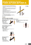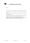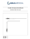
1
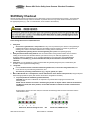
Banner AG4 Series Safety Laser Scanner Checkout Procedures
Shift/Daily Checkout
Perform the Daily Checkout procedure at every shift change, power-up and machine set-up change – and at intervals
not to exceed 24 hours during continuous machine run periods. Record a copy of the checkout results and store in
the appropriate place (e.g., near or on the machine, in the machine’s technical file).
Tester: Designated Person or Qualified Person
1.
Verify that:
Access to the guarded area is not possible from any area not protected by the Scanner. Hard guarding or
supplemental presence-sensing devices must be installed, wherever needed, to prevent any person from
reaching over, under or around the defined area or entering into the hazard area.
2.
3.
4.
All supplemental guarding devices and hard guarding are in place and operating properly.
Verify that the minimum safety distance from the closest hazard of the guarded machine to the Protective
Field(s) is not less than the calculated distance, per Sections 3.3.4 (U.S. stationary applications), 3.3.5
(European stationary applications), or 3.4.3 (mobile applications) of the instruction manual. Ensure this
information is recorded (e.g., printout of Protective Fields) and located at the machine for quick
reference.
Verify that: It is not possible for a person to stand inside the guarded (dangerous) area, undetected by the
Scanner or other supplemental safeguarding.
Verify that:
If used, the Reset switch is mounted outside the guarded area, in full view of the guarded area, and
out of reach of anyone inside the guarded area, and
5.
The means of preventing inadvertent use (e.g., rings or guards) is in place.
When LED indicator # 1 is steady Green, test the effectiveness of the Scanner with power ON, using the trip test.
Select the appropriate test piece (that matches the Scanner configuration resolution).
a. Trip Test (Protective and Warning Field Verification)
CAUTION: Ensure that no individuals are exposed to any hazard while verifying the Protective and
Warning Fields.
NOTE: The PC interface can assist in monitoring the position of objects and the status of the Protective
and Warning Fields, but when possible, use the LED indicators to determine whether a field has been
interrupted.
Ensure that the Scanner is in Run mode, the Protective and Warning Fields are clear of intrusions and the
LED indicators show:
1
2
3
4
1
5
Fields clear, Scanner waiting for reset
AG4 Scanner Checkout
OR
2
3
4
5
Fields clear, OSSDs are ON
P/N 147899 rev. A 02/2010
1
Banner AG4 Series Safety Laser Scanner Checkout Procedures
b.
c.
If a Warning Field is used: (with the guarded machine at rest) using the appropriate test piece (that
matches the configured/expected resolution) interrupt the Warning Field perimeter and verify LED #2
(Yellow) turns ON as expected. Remove the test piece and verify that LED #2 turns OFF. Repeat this
along the entire Warning Field perimeter as shown below. Pay special attention at needle and coneshaped areas.
With the guarded machine at rest, using the appropriate test piece (that matches the
configured/expected resolution) interrupt the perimeter of the Protected Field and verify LED #1
(Green) turns OFF. Remove the test piece and verify that LED #1 turns ON. Repeat this along the
entire Protective Field perimeter (see Figure below) and verify:
That the configured field responds to the intrusion of the test piece
That the configured field has no unmonitored areas.
That the separation (safety) distance is as calculated and recorded.
Note: Pay special attention at needle and cone-shaped areas
Note: For stationary applications, verify that the marking of the perimeter of the Protective Field
on the floor corresponds to LED #1. If the floor has not been marked, do so now, if possible,
with the aid of the response of LED #1.
The Green #1 indicator must remain OFF while the test piece remains in the Protective Field. If the
Green indicator comes ON at any time while the test piece is interrupting the Protective Field, the
installation has failed the trip test. Via a PC, check for correct Protective Field orientation and for
unguarded areas.
Do not continue with this checkout procedure or operate the guarded machine until the situation
is corrected and the indicators respond properly as described above.
d.
Verify the height of the Protective Field at the perimeter is at the expected level (e.g., 150 mm for
mobile applications).
Protective Fields 90º to 190º: In at least three locations, approx. 90º apart from each other.
Protective Fields 90º or less: In at least two locations, 90º apart from each other.
6.
Repeat steps 5b, 5c, and 5d for each of the Field Pairs that have been configured if Field Pair Switchover is
used. Ensure that all fields correspond to the expected fields as determined by the risk assessment. If not,
do not continue until the situation is corrected.
AG4 Scanner Checkout
P/N 147899 rev. A 02/2010
2
Banner AG4 Series Safety Laser Scanner Checkout Procedures
7.
8.
9.
After the Warning and Protective Fields have been verified, initiate machine motion of the guarded
machine or mobile vehicle. While it is moving, use the appropriate test piece to interrupt the Protective
Field. Do not attempt to insert the test piece into the dangerous parts of the machine or directly in
the path of the moving vehicle. Upon interrupting the Protective Field (at any point), verify that:
For stationary applications: The dangerous parts of the machine come to a stop with no apparent
delay. Remove the test piece from the Protective Field; verify that the machine does not
automatically restart, and that the initiation device(s) must be engaged to restart the machine.
For mobile applications: The vehicle stops within the identified/predetermined distance. Remove the
test piece from the Protective Field; verify that the vehicle does not unintentionally restart, and, if
required, that the initiation device(s) must be engaged to restart the mobile vehicle. This must be
accomplished at numerous points along the entire route (i.e., testing each of the Field Pairs in the
configuration).
With the guarded machine at rest, insert the test piece into the defined area and verify: The guarded
machine cannot be put into motion while the test piece is in the defined area.
Check carefully for external signs of damage or changes to the Scanner, the guarded machine, and
their electrical wiring. Immediately report any damage or changes found to management.
Do not continue operation until the entire checkout procedure is complete and all problems are
corrected.
AG4 Scanner Checkout
P/N 147899 rev. A 02/2010
3
Banner AG4 Series Safety Laser Scanner Checkout Procedures
Semi-Annual Checkout
Perform the Semi-Annual Checkout procedure every six months following system installation, or whenever changes
are made to the Scanner configuration or to the machine). Print out the instructions to be posted near the
installation/guarded machine, for easy reference. A copy of the checkout results should be recorded and kept in the
appropriate place (e.g., near or on the machine, in the machine’s technical file).
Tester: Qualified Person (as described in Section 4.1 of the manual).
To prepare for this checkout, configure the Scanner as it will be during machine operation.
The Qualified Person must:
1.
2.
3.
4.
5.
6.
7.
Examine the guarded machine to verify that it is of a type and design compatible with the Scanner. See Section
1.5 of the Instruction Manual for more information.
Connect the PC to the X2 connection and verify correct configuration of all Protective/Warning Field
Pairs. Ensure the reference contour (surface) monitoring is correct (especially in stationary vertical
Protective Field applications).
Verify that the minimum safety distance from the closest hazard point of the guarded machine to the
Protective Field(s) is not less than the minimum distance calculated in Section 3.3.4 or 3.3.5 of the instruction
manual. Verify that this information is recorded (e.g., a printout of the Protective Fields) and located at the
machine for quick reference.
Verify that:
a. Access to any dangerous parts of the guarded machine is not possible from any direction not
protected by the Scanner, hard guarding, or supplemental safeguarding, and
b. It is not possible for a person to stand between the Protective Field(s) and the dangerous parts of the
machine, or
c. Supplemental safeguarding and hard guarding, as described by the appropriate safety standards, are
in place and functioning properly in any space (between the Protective Field(s) and any hazard) which is
large enough to allow a person to stand undetected by the Scanner.
Verify that:
a. If used, the Reset switch is mounted outside the guarded area, in full view of the guarded area, and
out of reach of anyone inside the guarded area, and
b. The means of preventing inadvertent use (e.g., rings or guards) is in place.
Examine the electrical wiring connections between the Scanner OSSD outputs and the guarded machine’s
control elements to verify that the wiring meets the requirements stated in Section 3.7 of the User Manual.
Verify that power to the guarded machine is OFF and apply power to the Scanner. Remove all obstructions
from the Protective Field(s). Observe the LED status indicators to identify the Scanner Status. If, at any time, a
Status indicator begins to flash, the Scanner has entered an error or lockout condition. See User Manual Section
5 for further information.
Typical LED indications (assumed Warning Field controls Alarm 1):
a. Protective and Warning Fields clear
- OSSD and Alarm 1 (Auxiliary) outputs ON
1
2
3
4
5
b. Protective Field clear, Warning Field interrupted
- OSSD outputs ON
- Alarm 1 (Auxiliary) OFF
1
AG4 Scanner Checkout
P/N 147899 rev. A 02/2010
2
3
4
5
4
Banner AG4 Series Safety Laser Scanner Checkout Procedures
c. Protective and Warning Fields interrupted
- OSSD and Alarm 1 (Auxiliary) outputs OFF
1
2
3
4
5
1
2
3
4
5
1
2
3
4
5
d. Protective Field clear, Warning Field interrupted
- OSSD outputs held OFF
- Alarm 1 (Auxiliary) OFF
e. Protective and Warning Fields clear
- OSSD outputs OFF and waiting for start/restart (reset)
- Alarm 1 (Auxiliary) output ON
8.
9.
If the fields are in a clear condition (7a or 7e), go to step 10. If in a Lockout condition, refer to Section 5 of
the User Manual. A Blocked condition indicates that one or more obstructions are within the Protective Field. To
correct this situation:
a. Check carefully for any obstruction(s) in the Protective Field and remove them.
b. If the defined area is completely clear of obstructions, check alignment.
If the System is configured for Start/Restart (Manual Reset) mode, the #5 indicator will be ON. Perform a
manual reset (close the reset switch for 1/4 to 5 seconds, then open the switch). Verify that the #1 and #4
indicators are ON steady.
When the #1 LED status indicator is Green, perform the trip test for each Protective Field (described on the Daily
Checkout card) to verify proper System operation and to detect possible unmonitored areas.
AG4 Scanner Checkout
P/N 147899 rev. A 02/2010
5
Banner AG4 Series Safety Laser Scanner Checkout Procedures
10. Apply power to the guarded machine and verify that the machine does not start up. Insert the test piece
into the Protective Field and verify that it is not possible for the guarded machine to be put into motion while a
beam is blocked.
11. After the Warning and Protective Fields have been verified, initiate the machine motion of the guarded
machine or mobile vehicle. While it is moving, use the appropriate test piece to interrupt the Protective Field.
Do not attempt to insert the test piece into the dangerous parts of the machine or directly in the path of
the moving vehicle. Upon interrupting the Protective Field (at any point), verify that:
For stationary applications: The dangerous parts of the machine come to a stop with no apparent delay.
Remove the test piece from the Protective Field; verify that the machine does not automatically restart,
and that the initiation device(s) must be engaged to restart the machine.
For mobile applications: The vehicle stops within the identified/predetermined distance. Remove the test
piece from the Protective Field; verify that the vehicle does not unintentionally restart, and, if required,
that the initiation device(s) must be engaged to restart the mobile vehicle. This must be accomplished at
numerous points along the entire route (i.e., testing each of the Field Pairs in the configuration).
12. Remove electrical power to the Scanner. All OSSD outputs should immediately turn OFF, and should not be
capable of turning ON until power is re-applied and, if in Start/Restart (Manual Reset) mode, a manual reset is
performed (Automatic Start (Reset) mode requires no manual reset).
13. Test the machine stopping response time, using an instrument designed for that purpose, to verify that it is
the same or less than the overall system response time specified by the machine manufacturer. (Banner’s
Applications Engineering Department can recommend a suitable instrument.)
Do not continue operation until the entire checkout procedure is complete and all problems are
corrected.
14. If any decrease in machine braking ability has occurred, make the necessary clutch/brake repairs, readjust
minimum safety distance (“Ds” or “S”) appropriately. Verify that this information is recorded (e.g., a printout of
Protective Fields) and located at the machine for quick reference.
15. Examine and test the machine primary control elements (MPCEs) and any intermediary controls (such as
interface modules) to verify that they are functioning correctly and are not in need of maintenance or
replacement.
16. Inspect the guarded machine to verify that no other mechanical or structural problems could prevent the
machine from stopping or assuming an otherwise safe condition when signaled to do so by the SCANNER.
17. Examine and inspect the machine controls and connections to the Scanner to verify that no modifications
have been made which adversely affect the system. Verify that any changes made to the Scanner configuration
and Protective/Warning Fields dimensioning have been recorded.
Do not continue operation until the entire checkout procedure is complete and all problems are corrected.
AG4 Scanner Checkout
P/N 147899 rev. A 02/2010
6