1
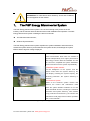
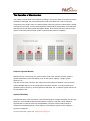
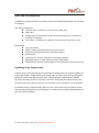
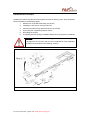
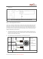
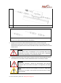
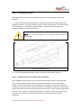
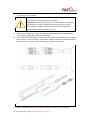
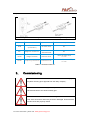
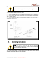
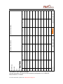
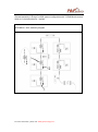
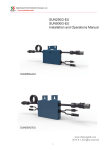
P&P ENERGY Microinverter Models PMI-250-P Installation Manual For more information ,please visit :www.ppnewenergy.com Contact Information P&P ENERGY TECHNOLOGY CO., LIMITED No.100 Waihuan Xi Road, Guangzhou Higher Education Mega Center, Panyu District, Guangzhou, P.R China (510006) http://www.ppnewenergy.com/ [email protected] +86-020-39323011 For more information ,please visit :www.ppnewenergy.com Table of Contents Read Before Installation ............................................................................................................ 4 Safety Instructions..................................................................................................................... 4 1、 The P&P ENERGY Microinverter System ...................................................................... 5 The Operation of Microinverters........................................................................................... 6 Outshine System Monitor ...................................................................................................... 6 Optimal Reliability ................................................................................................................... 6 Ease of Design........................................................................................................................ 7 2、 P&P Energy Microinverter installation ............................................................................. 7 Compatibility and Capacity ................................................................................................... 8 Parts and Tools Required ........................................................................................................... 9 Lightning Surge Suppression ..................................................................................................... 9 Installation Procedure ............................................................................................................. 10 Step 1 – Measure AC at the Electrical Utility Connection ....................................................... 11 Step 2 – Install the AC Branch Circuit Junction Box Mount the P&P Adapter ......................... 11 Step 3 - Attach the P&P Microinverters to the Racking .......................................................... 12 Step 4 - Connecting the Microinverters .................................................................................. 14 Step 5 – Grounding the System ............................................................................................... 16 Step 6 – The Microinverter location of the installation .......................................................... 16 3、 Commissioning ................................................................................................................. 18 4、 Operating Instructions...................................................................................................... 19 5、 Troubleshooting.................................................................................................................. 20 Microinverter Status LED Indications and Error Reporting ............................................ 20 Startup LED Operation: ....................................................................................................... 20 Troubleshooting an Inoperable Microinverter .................................................................. 20 Disconnecting the P&P Microinverter from the PV Module ........................................... 21 6、 Appendix ............................................................................................................................. 22 Limited Warranty .................................................................................................................. 22 APPENDIX I- Wire assembly diagram .............................................................................. 25 APPENDIX II-Overall assembly diagram .......................................................................... 26 For more information ,please visit :www.ppnewenergy.com Safety Problem Read Before Installation This manual complied to direct the installer ,maintainer and system owner to know the operation stuatus of the P&P Energy Microinverter. To reduce the risk of electrical shock and keep the operators safety, the following safety symbols appear throughout this document to indicate dangerous conditions and important safety instructions. WARNING: This indicates a situation where failure to follow instructions may cause a serious hardware failure if not applied appropriately .Use extreme caution when performing this task. ATTENTION: This indicates information particularly important for optimal system operation. Follow these instructions closely. Safety Instructions Perform all electrical installations in accordance with all local electrical codes and the National Electrical Code (NEC). Be aware that only qualified person and staff could install and replace P&P Energy Microinverters. Do not attempt to repair the P&P Energy Microinverter; it is sealed by the polyurethane and contains vulnerable components inside. If it fails, please contact P&P Energy customer service to get an Replace number and start the replacement process. Tampering with or opening the P&P Energy Microinverter will void the warranty. Before installing or using the P&P Energy Microinverter, please read all instructions and cautionary markings in the technical description and on the P&P Energy Microinverter system and the PV-array. Connect the P&P Energy Microinverter to the electrical utility grid only after approved by the utility company. Be aware that the body of the P&P Energy Microinverter is the heat sink and can reach a temperature of 80°C. To reduce risk of burns, do not touch. Do NOT disconnect the PV module from the P&P Energy Microinverter without first removing AC power. For more information ,please visit :www.ppnewenergy.com ATTENTION: For P&P Microinverter Warranty Terms and Conditions, see the Appendix of this manual. 1、 The P&P Energy Microinverter System The P&P Energy Microinverter system is one of the most high-tech product in the PV industry ,and the manual direct the Microinverter’s safe installation and operation. The P&P Energy Microinverter system including the device hereunder: The PMI series Microinverter; Outshine System Monitor The P&P Energy Microinverter system simplifies the system installation and maintenance, elevate the system efficiency and maximizes the system harvest, and enlarge the system lifetime without high DC voltage employed. 1,P&P Energy Microinverters Each microinverters allow each PV module to operate independently for a higher performance and energy harvest ;With the standard AC and DC connector ,simplified the system installation process and enhance the system expandability . 2,Outshine system monitor Put the intelligence to the system ,and the owners could check the system status by the LCD display ,including the system capacity ,the electricity production ,the system efficiency in real time . 3,PC Enhance System Based on the Outshine system monitor and network ,the owners and maintainers could check the system detailed condition on PC and Smart handheld devices ,including the historical production and system efficiency ,each module timely production and efficiency ,the owners and maintainers could judge if the module's operation well or need maintain . Fig. 1.1 System integration For more information ,please visit :www.ppnewenergy.com The Operation of Microinverters The majority of solar panel in the market is including 2 circuit ,so if either of the panel circuits is sheltered or damaged ,the solar panel efficiency will low at least 50% ,and if the system composed by the string inverter ,the whole system’s efficiency will low to same with the lowest solar panel in the string ,and the remaining power will elevate the temperature in the fault point (although some solar panel install with Bypass diode) ,and increase the risk of the fire for the system .Fortunately ,Microinverter system could avoid the problem completely . Outshine System Monitor Based on the PLC technology ,the system owner could check the Microinverter system’s general information by the LCD display ,such as the system capacity ,voltage ,system efficiency ,etc. And after connect to the Internet ,the system owner and system maintainer could check the system detailed status in PC and smart phone anywhere ,anytime .Including module-level generated power ,efficiency ,and the system PV fault point ,etc. To help the system owners cut the maintenance fee . Optimal Reliability Each Microinverter ,each solar panel ,could avoid the high DC voltage employed ,plus the high efficiency ,could extend the Microinverter lifetime to 25years .And all the body sealed by polyurethane to reach the enclosure IP67(NEMA6 ) ,keep the internal PCB board and components isolated absolutely .These features could help the system owner cutting the long-term investment . For more information ,please visit :www.ppnewenergy.com The details of the enclosure test IP67(NEMA6) : 6 :Test duration :at least 3minutes ;Water volume :100litres per minute ;Pressure :100kPa at distance of 3m 7 :Test duration :at least 30minutes ;The lowest point of enclosures with a height less than 850mm is located 1000mm below the surface of the water ,the heighest point of enclosures with a height equal to or greater than 850mm is located 150mm below the surface of the water . Ease of Design The Microinverter system is much easy to design and installation .You will not need string calculations, and you can install individual PV modules in any combination of PV module quantity, type, age and orientation. You won’t need to install cumbersome traditional inverters. Each Microinverter quickly mounts on the PV racking, directly beneath each PV module. Low voltage DC wires connect from the PV module directly to the co-located Microinverter, eliminating the risk of personnel exposure to lethal 600Vdc power. 2、 P&P Energy Microinverter installation The installation of P&P Energy Microinverter system is very easy .Each Microinverter quickly tie on the PV panel bracket ,directly beneath each PV module ;Then connect the Microinverter with the low DC voltage PV module via MC4 ;Connect the continuous Microinverter with standard AC connector to build a branch ,each branch original cable could support 20A branch current . Maximum number of each AC branch circuit : Voltage Maximum number each branch 110V 8units 220V 17units 208V(Triple phase) 25units For more information ,please visit :www.ppnewenergy.com WARNING: Be aware that only qualified personnel should connect the P&P Energy Microinverter to the electrical utility grid. WARNING: Be aware that installation of this equipment includes risk of electric shock .Normally grounded conductors may be ungrounded and energized when a ground fault is indicated. Compatibility and Capacity The P&P Energy PMI-250 Microinverters recommended match solar panel 250W-310W 60-cell and 72-cell PV modules .And each Microinverters have a couple of standard Amphenol MC4 connectors . To ensure mechanical compatibility, be sure to order the correct connector type for both Microinverter and PV module from your distributor . For more information ,please visit :www.ppnewenergy.com Parts and Tools Required In addition to the Microinverters ,PV modules ,bracket ,and associated hardware ,you will need the following . P&P Energy Equipment : Terminal cable ,as needed (to access into the utility grid) Cable clips Sealing caps ,as needed (one needed to keep waterproof in the terminal AC connector of a branch) Terminators, as needed (one needed at the end of each AC branch circuit) Other Items AC junction boxes Gland or strain relief fitting (one per AC junction box) Continuous grounding conductor, grounding washers Screwdrivers Torque wrench ,sockets ,wrenches for mounting hardware Adjustable wrench or open-ended wrench (for terminators) Handheld mirror (to view indicator lights on the undersides of the Microinverters) Lightning Surge Suppression Lightning does not actually damage the equipment or building where the system installed ,but a strike will result the voltage spikes in the power grid in a certain region and will damage the equipment .P&P Energy Microinverters have a high properties surge protection realized by EPCOS S14K275 ,S14K140 ,P14V420 . However, if the surge has sufficient energy ,the protection built into the Microinverter can be exceeded, and the equipment can be damaged. As the P&P Energy Limited Warranty does not cover “acts of God” such as lightning strikes, and since lightning strikes can occur anywhere, it is best practice to install surge protection as part of any solar installation. For more information ,please visit :www.ppnewenergy.com Installation Procedure Installing the P&P Energy Microinverter System involves several key steps. Each step listed below is detailed in the following pages. 1. Measure AC at the Electrical Utility Connection 2. Installing the AC branch circuit junction box 3. Attaching the P&P Energy Microinverters to the racking 4. Connecting the neighbouring Microinverters 5. Grounding the system 6. Completing the P&P Energy Installation Map and Connecting the PV Modules WARNING: DO NOT connect P&P Energy Microinverters to the utility grid or energize the AC circuit(s) until you have completed all of the installation procedures as described in the following sections . Fig. 2.1 Installation Procedure For more information ,please visit :www.ppnewenergy.com Step 1 – Measure AC at the Electrical Utility Connection Measure AC line voltage at the electrical utility connection to confirm that it is within range. Acceptable ranges are shown in the following table Single-phase 240Volt AC L1 to L2 211VAC to 264VAC L1,L2 to Neutral 106VAC to 132VAC Triple-phase 208Volt AC A to B to C 183VAC to 229VAC A,B,C to Neutral 106VAC to 132VAC Fig. 2.2 AC line voltage measure NOTE: Check the labeling on the AC Cable drop connectors to be sure that the cable matches the electrical utility service at the site .Use 208 VAC (208 VAC three-phase) AC Cable at sites with three-phase 208 VAC service ,or use 240 VAC AC Cable at sites with 240 VAC single-phase service .Use 240 VAC cable at sites with 208 single-phase services . Step 2 – Install the AC Branch Circuit Junction Box Mount the P&P Adapter Install an appropriate junction box with adapter plate. DANGER :Risk of Electrical Shock .Must operate with qualified personnel .Be aware that installation of this equipment includes risk of electric shock .Do not install the AC junction box without first removing AC power from the P&P Energy System . WARNING :Only use electrical system components approved for wet locations . For more information ,please visit :www.ppnewenergy.com WARNING :Do NOT exceed the maximum number of Microinverters in an AC branch circuit as listed .The qualified personnel must protect each Microinverter AC branch circuit with a 20A maximum breaker . A. Mount the P&P adapter Plate at a suitable location on the PV racking system (typically at the end of a row of modules). B. Install an appropriate junction box with adapter plate. C. Connect the open wire end of the P&P Energy AC interconnect cable into the junction box using an appropriate gland or strain relief fitting. D. Route the continuous Grounding Electrode Conductor (GEC) through the grounding clamp of each Microinverter. Check local code requirements for the gauge of the GEC. Fig. 2.2 Install the AC branch junction box Step 3 - Attach the P&P Microinverters to the Racking A. Mark the approximate centers of each PV module on the racking system. Evaluate the location of the Microinverter with respect to the PV module junction box or any other obstructions. B. Mount one Microinverter at each of these locations using hardware recommended by your module racking vendor. For more information ,please visit :www.ppnewenergy.com Fig. 2.3 Mounting PMI250 on racking For more information ,please visit :www.ppnewenergy.com C. The gap distance between the roof surface and the back of the PV modules needs to be at least 1 cm. Fig. 2.4 The necessary gap for the PMI micro inverter’s back side Step 4 - Connecting the Microinverters There have 2 categories of Microinverters :single phase (3pin) and triple phase (4pin) ,each Microinverter use copper multi-pin inside the connector and guarantee the better electrical conductivity ,and the AC connectors are oppositely sexed ,so that multiple Microinverters can be connected to form a continuous AC branch circuit easily .And you could refer the wiring diagram underneath for profound known . A. The first Microinverter in each branch with male connector facing the junction box ,the junction box has a female connector ,the Microinverter can be mounted with either side facing to accommodate cable routing . B. The conductivity pin number depending on your Microinverter model: For L1-Black L-N-L N-Yellow- system PIN1-Black green PIN2-Yellow-green L2-Black For L-N L-Black system N-Black PIN3-Black PIN4-Black(3Phase) For 3 A- Black phase B- Black system C- Black N- Empty(1Phase) Yellowgreen Fig. 2.5 AC cable definition with multy pin connector For more information ,please visit :www.ppnewenergy.com Fig. 2.6 AC cable connection Fig. 2.7 Connect the continuous Microinverter’s Male & Female AC connectors ,and the end cap on the last inverter at the end of the branch . C. Plug the AC connector of the first Microinverter into the connector of the next Microinverter ,and so forth ,to form a continuous AC branch circuit .Please check the Microinverter rating label for the maximum allowable number of Microinverters on one AC branch circuit. WARNING :Do NOT exceed the maximum number of Microinverters in an AC branch circuit ,as displayed on the unit-rating label .Each Microinverter AC branch circuit must be sourced from a dedicated branch circuit protected by a 15A maximum breaker . D. Install a protective end cap on the open AC female connector of the last Microinverter in the terminal .Do not exceed 18 units of PMI Microinverters connected per branch . WARNING :Make sure protective end caps have been installed on all unused AC connectors .Unused AC Microinverter wire harness connectors will be live when the system is energized by the utility system . NOTE :Be sure to size the AC wire gauge to account for voltage drop between the AC branch circuit junction box and the point of utility interconnection . For more information ,please visit :www.ppnewenergy.com Step 5 – Grounding the System Each P&P Microinverter comes with a ground clip that can accommodate a 6-10 AWG conductor. A. Route a continuous GEC through each of the Microinverters to the NEC approved AC grounding electrode .The bracket and PV module could be grounded to this conductor using a crimp connection .An alternative method would be to connect the Microinverter to the grounded bracket using a grounding washer . NOTE :The AC output neutral is not bonded to ground inside the Microinverter . Fig. 2.8 Grounding lay-in lug B. Use a recommended grounding lug with a continuous ground wire, see Fig. 3 Step 6 – The Microinverter location of the installation After installation of the Microinverter ,you could record the Microinverter’s physical location (row ,column) in the PV system .When you finished the diagram ,then you could input it location information into the P&P Energy Outshine solar system if you installed it .After this procedure ,you could check the system information and condition by P&P server based on the internet .Each Microinverter has a unique S/N code on the top or surface ,and P&P will provide you after service based on the information feedback if it possible .And the PV system owner could check the system module-level status based on the location diagram via PC or smartphone . For more information ,please visit :www.ppnewenergy.com To connect your PV modules : NOTE :Completely install all Microinverters and all system inter-wiring connections prior to installing the PV modules. Best Practice :Test AC first .Before you rack-mount the PV , pull and terminate all AC wiring ,energize the branches ,and power up the Microinverters to make sure that they all report into the Outshine monitor system and are operating correctly . A. Install the PV modules above their corresponding Microinverters .Each Microinverter comes with two oppositely sexed MC4 connectors . B. First connect the positive MC4 connector from PV module to the Microinverter’s negative MC4 connector .Then connect the PV module’s negative connector to the Microinverter’s positive connector .Repeat for the remaining PV modules in the system . Fig. 2.9 Connect the DC connector to the PMI Micro inverter C. Each PV module branch must include protection devices ,the function setting of For more information ,please visit :www.ppnewenergy.com protection devices as shown hereunder : Fig. 2.10 General configuration of PMI Micro inverter to grid utility Symbol Na me Spe ci fications Settin gs NFB No Fu se B r eaker (AC B r eaker ) 2P 3 0AF 20AT NC MC Magnetic C ontactor AC240V 3kW/ 4HP/28A NC U/OVP Voltage Protection Klemsan VP35 184V UVP, 264V OVP, 0.1 s ec U/ OFP Fr equ ency Pr otection K lemsan FP3 5 47.5Hz UFP, 50.2Hz OFP, 0.1 s ec Table 2.1 Protection Devices 3、 Commissioning WARNING: Connect the P&P Microinverter to the electrical utility grid only after receiving prior approval from the utility company . WARNING: Be aware that only qualified personnel must connect the P&P Microinverter to the electrical utility grid . WARNING: Ensure that all AC and DC wiring is correct. Ensure that none of the AC and DC wires are pinched or damaged .Ensure that all junction boxes are properly closed . For more information ,please visit :www.ppnewenergy.com Note: The Status LED of each Microinverter will blink red 15 times to indicate normal start-up operation once DC power is applied . To commission the P&P Microinverter PV system : 1. Turn ON the AC dis-connects or circuit breaker on each Microinverter AC branch circuit . 2. Turn ON the main utility-grid AC circuit breaker . Your system will start producing power after a 1-minute wait time. 3. The P&P Microinverters will start to send performance data over PLC communication to the Outshine system monitor . Fig. 3.1 Connection configuration with branch breaker 4、 Operating Instructions NOTE: In the event of a GFDI failure, the status LED will display continuous red after the fault occurs .This will persist when AC and DC power are cycled to the Microinverter . You can verify proper operation of the P&P Microinverters via the PMsmart. See the PMsmart Installation and Operation Manual for more information. For more information ,please visit :www.ppnewenergy.com 5、 Troubleshooting Adhere to all the safety measures described throughout this manual. Qualified personnel can use the following troubleshooting steps if the PV system does not operate correctly: WARNING: Do not attempt to repair the P&P Microinverter; it contains no user-serviceable parts. If it fails, please contact P&P customer service to obtain an replace number and start the replacement process. Microinverter Status LED Indications and Error Reporting Startup LED Operation: Red On – Grid tie DC PV module ,ready to start ; Red Flash – 2s/time ,15times ,starting ; Green Flash – Operating . For More Operation Status ,you could check by the Outshine System Monitor and Enhanced System via PC and smartphone . WARNING :Be aware that only qualified personnel should troubleshoot the PV array or the P&P Microinverter . WARNING :Never disconnect the DC wire connectors under load . Ensure that no current is flowing in the DC wires prior to disconnecting . An opaque covering may be used to cover the module prior to disconnecting the module . WARNING :Always disconnect AC power before disconnecting the PV module wires from the P&P Microinverter .The AC connector of the first Microinverter in a branch circuit is suitable as a disconnecting means once the AC branch circuit breaker in the load center has been opened . Troubleshooting an Inoperable Microinverter To troubleshoot an Inoperable Microinverter ,follow the steps in the order shown : 1、 Check the connection to the utility grid .Verify the utility voltage and frequency is within allowable ranges shown in the PMI-250 Specifications .Verify utility power is present at the inverter in question by removing AC ,then DC power For more information ,please visit :www.ppnewenergy.com Never disconnect the DC wires while the Microinverter is producing power .Re-connect the DC module connectors and watch for red flashing . 2、 Check the AC branch circuit interconnection harness between all the Microinverters .Verify each Microinverter is energized by the utility grid as described in the previous step . 3、 Make sure that any AC disconnects are functioning properly and are closed . 4、 Verify the PV module DC voltage is within the allowable range shown in the PMI-250 specification . 5、 Check the DC connections between the Microinverter and the PV module . 6、 If the problem persists, please call customer support at P&P Energy or local distributor . WARNING: Do not attempt to repair the P&P Microinverter ;it contains no user-serviceable parts .If troubleshooting methods fail, please return the Microinverter to your distributor for maintenance . Disconnecting the P&P Microinverter from the PV Module To ensure the Microinverter is not disconnected from the PV modules under load ,adhere to the following disconnection steps in the order shown : 1、 Disconnect the AC by opening the branch circuit breaker . 2、 Disconnect the first AC connector in the branch circuit . 3、 Cover the module with an opaque cover . 4、 Using a DC current probe ,verify there is no current flowing in the DC wires between the PV module and the Microinverter . 5、 Care should be taken when measuring DC currents ,most clamp-on meters must be zeroed first and tend to drift with time . 6、 Disconnect the PV module DC wire connectors from the Microinverter . 7、 Remove the Microinverter from the PV array racking . For more information ,please visit :www.ppnewenergy.com 6、 Appendix Limited Warranty P&P Energy Technology Co., Ltd(P&P Energy) has developed a highly reliable micro inverter ,designed as the Series PMI-250 ,that is designed to withstand normal operating conditions when used for its originally intended purpose in compliance with the P&P Energy User Manual made available with the originally shipped system .The P&P Energy Limited Warranty covers defects in workmanship and materials of the P&P Energy Micro Inverter (”Defective Product ”) for a period of fifteen (15) years from the date of original purchase of such Micro Inverter at point of sale to the system owner (”Warranty Holder ”) at the originally-installed end user location (”Warranty Period ”) . During the Warranty Period, if P&P Energy establishes ,through inspection ,the existence of a defect that is covered by the Limited Warranty ,P&P Energy will at its option ,either (1) repair or replace the Defective Product free of charge, or (2) issue a credit or refund for the Defective Product to the Warranty Holder in an amount up to its actual value at the time the Warranty Holder notifies P&P Energy of the defect ,as determined by P&P Energy . If P&P Energy elects to repair or replace the Defective Product ,P&P Energy will at its option ,use new and/or reconditioned parts in repairing or replacing the Defective Product ,P&P Energy reserves the right to use parts or products of original or improved design in the repair or replacement of Defective Product .If repairs or replaces a Defective Product ,the Limited Warranty continues on the repaired or replacement product for the remainder of the original Warranty Period or ninety (90) days from the date of P&P Energy’s return shipment of the repaired or replacement product ,whichever is later .The Limited Warranty covers a replacement unit to replace the Defective Product ,but does not include shipping cost . P&P Energy Micro Inverter are designed to withstand normal operating conditions and typical wear and tear when used for their original intent and in compliance with the installation and operating instructions supplied with the original equipment .The Limited Warranty does not apply to ,and P&P Energy will not be responsible for ,any defect in or damage to any P&P Micro Inverter :(1)that has been misused , neglected ,tampered with ,altered ,or otherwise damaged ,either internally or externally ;(2)that has been improperly installed ,operated ,handled or used , including use under conditions for which the product was not designed ,use in an unsuitable environment ,or use in a manner contrary to the P&P Energy User Manual or applicable laws or regulations ;(3)that has been subjected to fire ,water , generalized corrosion ,biologicalinfestations ,acts of God ,or input voltage that creates operating conditions beyond the maximum or minimum limits listed in the P&P Energy Micro Inverter specifications ,including high input voltage from generators or lightning strikes ;(4)that has been subjected to incidental orconsequential damage caused by defects of other components of the solar system ;or (5) if the original identification markings (including trademark or serial number) For more information ,please visit :www.ppnewenergy.com of such Micro Inverter have been defaced ,altered ,or removed .This Limited Warranty does not cover cosmetic ,technical or design defects ,or shortcomings which do not materially influence or affect the energy production or degrade form , fit ,or function of the P&P Energy Micro Inverter . To obtain repair or replacement service ,credit or refund (as applicable) under this Limited Warranty ,the Warranty Holder must comply with the Return Merchandise Authorization Number (RMA) policy and procedure .P&P Energy expressly reserves the right to novate or assign its rights and obligations under this warranty agreement to a third party with the demonstrated expertise and requisite resources needed to effectively discharge the obligations hereunder . THE LIMITED WARRANTY IS THE SOLE AND EXCLUSIVE WARRANTY GIVEN BY P&P ENERGY AND ,WHERE PERMITTED BY LAW, IS MADE EXPRESSLY IN LIEU OF ALL OTHER WARRANTIES ,EXPRESS OR IMPLIED ,STATUTORY OR OTHERWISE ,INCLUDING ,WITHOUT LIMITATION ,WARRANTIES OF TITLE ,QUALITY ,MERCHANTABILITY ,FITNESS FOR A PARTICULAR PURPOSE OR NON-INFRINGEMENT OR WARRANTIES AS TO THE ACCURACY , SUFFICIENCY OR SUITABILITY OF ANY TECHNICAL OR OTHER INFORMATION PROVIDED IN MANUALS OR OTHER DOCUMENTATION .IN NO EVENT WILL P&P ENERGY BE LIABLE FOR ANY SPECIAL ,DIRECT ,INDIRECT ,INCIDENTAL OR CONSEQUENTIAL DAMAGES ,LOSSES ,COSTS OR EXPENSES HOWEVER ARISING ,WHETHER IN CONTRACT OR TORT ,INCLUDING WITHOUT LIMITATION ANY ECONOMIC LOSSES OF ANY KIND ,ANY LOSS OR DAMAGE TO PROPERTY ,OR ANY PERSONAL INJURY . To the extent any implied warranties are required under applicable law to apply to the P&P Energy Micro Inverter ,such implied warranties shall be limited in duration to the Warranty Period ,to the extent permitted by applicable law .Some regions do not allow limitations or exclusions on implied warranties or on the duration of an implied warranty or on the limitation or exclusion of incidental or consequential damages ,so the above limitation(s) or exclusion(s) may not apply .This Limited Warranty gives the Warranty Holder specific legal rights ,and the Warranty Holder may have other rights that may vary from region to region .The grant of this Limited Warranty by P&P Energy is conditioned upon agreement by the Warranty Holder and any permitted Transferee to the terms ,conditions and requirements herein . For more information ,please visit :www.ppnewenergy.com EMU Serial Label APPENDIX I- Wire assembly diagram General assembly in Europe: the wire assembly configuration for 18 PMI-250 Microinverters in 1 branch. For more information ,please visit :www.ppnewenergy.com Fax to: K G I H G F E D C B 1 A of Sheet Tilt: Azimuth: Panel Group: 2 3 Customer information: 4 5 Installer information: 6 7 INSTALLATION MAP P&P Microinverter Installation Location APPENDIX I- Wire assembly diagram General assembly in Europe: overall system configuration with 72 PMI Microinverters, which is 6 (six) branches for 1 system. APPENDIX I- Wire assembly diagram For more information ,please visit :www.ppnewenergy.com APPENDIX II-Overall assembly diagram For more information ,please visit :www.ppnewenergy.com P&P ENERGY TECHNOLOGY CO., LIMITED No.100 Waihuan Xi Road Guangzhou Higher Education Mega Center Panyu District, Guangzhou P.R China (510006) 86-020-39323011 http://www.ppnewenergy.com/ [email protected] For more information ,please visit :www.ppnewenergy.com