1
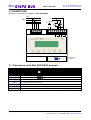
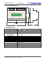
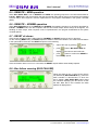
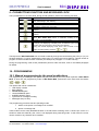
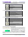
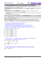
DUEMMEGI
MiniDISP2 BUS
MiniDISP2 BUS
ALARMS AND TEXT DISPLAY
User's manual
Release 1.0 - July 2007
HOME AND BUILDING AUTOMATION
Via Longhena 4 - 20139 MILANO
Tel. 02/57300377 - FAX
02/55213686
www.duemmegi.it
MiniDISP2 BUS
User's manual
DUEMMEGI
INDEX
1- INTRODUCTION.......................................................................................................................................... 3
2- Mini DISP2 BUS: MAIN FEATURES............................................................................................................. 3
3- CONNECTIONS........................................................................................................................................... 4
3.1 - Description of the Mini DISP2 BUS terminals...................................................................................... 4
4 - OUTLINE DIMENSIONS.............................................................................................................................. 5
5 - TECHNICAL DATA...................................................................................................................................... 5
6 - INPUT AND OUTPUT POINTS................................................................................................................... 6
7 – OPTIONS SETTING...................................................................................................................................
7.1 - Display contrast...................................................................................................................................
7.2 - Mini DISP2 BUS address.....................................................................................................................
7.3 - Memory option.....................................................................................................................................
7.4 - Local/Remote option............................................................................................................................
7.5 – Buzzer option......................................................................................................................................
7.6 - Cycle time............................................................................................................................................
7.7 - Alarm outputs......................................................................................................................................
7
7
7
7
7
7
8
8
8 - FUNCTIONAL DESCRIPTION.................................................................................................................... 8
8.1 - Operating modes................................................................................................................................. 8
8.2 - Relay operation in LOCAL mode......................................................................................................... 9
8.3 - LOCAL – MEM operation..................................................................................................................... 9
8.4 - LOCAL – NOMEM operation............................................................................................................... 9
8.5 - REMOTE – MEM operation............................................................................................................... 10
8.6 - REMOTE – NOMEM operation ......................................................................................................... 10
8.7 - RESET of alarms............................................................................................................................... 10
8.8 - Bus failure warning (BUS FAILURE).................................................................................................. 10
9 - PUSHBUTTONS FUNCTION AND KEYBOARD LOCK............................................................................ 11
10 - PROGRAMMING..................................................................................................................................... 11
10.1- Manual programming by the panel pushbuttons............................................................................... 11
10.2- Programming by Personal Computer................................................................................................ 12
11 - PROGRAMMING MCP IN Mini DISP2 BUS APPLICATIONS.................................................................. 13
11.1- Example for keyboard lock............................................................................................................... 14
Page 2 of 14
Rel.: 1.0 July 2007
DUEMMEGI s.r.l. - Via Longhena, 4 – 20139 MILANO
Tel. 02/57300377 - Fax 02/55213686 – www.duemmegi.it
DUEMMEGI
User's manual
MiniDISP2 BUS
1- INTRODUCTION
The display DUEMMEGI Mini DISP2 BUS is a device allowing to report, in a customized way, messages for
controlling purpose in many applications, such as industrial and domestic plants. Thanks to its flexibility, the
display Mini DISP2 BUS makes easy to understand any information related to the occurrence of alarms or
events. These devices can be employed in several applications as in the following examples:
✗
Machinery
✗
Building automation
✗
Industrial processing
✗
Home automation
✗
Plants
✗
Alarm signaling
Mini DISP2 BUS is offered as an option, in a different housing, of the previous version DISP2 BUS.
2- Mini DISP2 BUS: MAIN FEATURES
✗
LCD display 2 x 16 characters with back-lighting
✗
2 operating mode: with memory (MEM) or
without memory (NOMEM)
✗
LCD contrast may be adjusted by the button on
the front panel
✗
Events are displayed in chronological order (up
to 64); information about the total amount of
pending alarms
✗
Message programming by front panel
pushbuttons or by PC
✗
Cyclic displaying of more messages; the cycle
time may be set by user in the range 1 to 10
seconds
✗
Messages and parameters stored into Mini
DISP2 BUS memory may be read by a PC
✗
Internal buzzer for alarm acoustic signaling; the
buzzer operation may be disabled
✗
Messages are recalled by the bus line
DUEMMEGI Contatto
✗
2 potential free contacts (internal relays) and
buzzer (directly handled by DISP2 BUS in
LOCAL mode ore via bus in REMOTE mode) for
additional acoustic/visual signaling (siren and
flasher)
✗
255 messages made by 2 main lines and 2
auxiliary lines
✗
The status of the buttons on the front panel can
be acquired via bus
✗
1 base message made by 2 lines (stand-by
message)
✗
ACK and RESET commands can be forced via
bus
✗
1 alarm pending message made by 2 lines
✗
Keyboard lock to avoid unwanted operations by
unauthorized personnel
The firmware of Mini DISP2 BUS device can be easily updated “on the field” by the user through a PC
connected via RS232 communication port by the provided cable; this feature allows future developments of
the product concerning new functions and possible special versions. For more details about this feature,
contact DUEMMEGI. commercial office.
DUEMMEGI s.r.l. - Via Longhena, 4 – 20139 MILANO
Tel. 02/57300377 - Fax 02/55213686 – www.duemmegi.it
Rel.: 1.0 July 2007
Page 3 of 14
MiniDISP2 BUS
DUEMMEGI
User's manual
3- CONNECTIONS
The Figure 1 shows the wiring diagram of Mini DISP2 BUS
+24V
Vs
0V
L1
0V
Vout 0.5A MAX
L2
+24V
BUS
1
2
13 14 15 16 17
3
4
5
6
K1
7
8
9
K2
Programming
connector
3.1 - Description of the Mini DISP2 BUS terminals
Terminal
Function
± 25% SELV
13
Positive power supply +24V
14
Power supply common
15
L1 bus line of DUEMMEGI Contatto system
16
L2 bus line of DUEMMEGI Contatto system
17
Not connected
1-2
Power supply output (MAX 0.5A); terminal 1 is internally connected to terminal 13, terminal 2 is
internally connected to terminal 14.
3
Not connected
4-5-6
Potential-free contact of the internal relay K1 for driving an alarm device (e.g.. siren)
7-8-9
Potential-free contact of the internal relay K2 for driving an alarm device (e.g. flasher)
Page 4 of 14
Rel.: 1.0 July 2007
DUEMMEGI s.r.l. - Via Longhena, 4 – 20139 MILANO
Tel. 02/57300377 - Fax 02/55213686 – www.duemmegi.it
DUEMMEGI
MiniDISP2 BUS
User's manual
90mm
4 - OUTLINE DIMENSIONS
106mm
58mm
5 - TECHNICAL DATA
Current consumption
24V
± 25%
150mA MAX at 24V
Output voltage on terminals 1-2
Equal to that applied on terminals 13-14
Allowed current on terminals 1-2
0.5A MAX
Power supply
Output contacts:
Max switching voltage
Max switching current
Max operating power
(with terminals 1-2 not connected)
PC interface
60Vcc or 125Vca
1A
30W in cc / 60VA in ca
RS232C full duplex opto-coupled
Display
LCD with back-lighting, contrast adjustable by keyboard on front panel
Characters (each line)
16
Lines
2
Characters height
3 mm
Number of message
Connections
255 (4 lines each one) + 1 (stand-by message, 2 lines) + 1 (pending
messages, 2 lines)
By removable terminal blocks
Protection degree
IP20
Operating temperature
0 ÷ +50°C
Storage temperature
-10 ÷ +70°C
DUEMMEGI s.r.l. - Via Longhena, 4 – 20139 MILANO
Tel. 02/57300377 - Fax 02/55213686 – www.duemmegi.it
Rel.: 1.0 July 2007
Page 5 of 14
MiniDISP2 BUS
User's manual
DUEMMEGI
6 - INPUT AND OUTPUT POINTS
Mini DISP2 BUS behaves as an assemblage made by an input module and two output modules of
DUEMMEGI Contatto family. Said “x” the base address chosen for Mini DISP2 BUS, the following input
points and output points will be available:
Input points:
Indirizzo/punto
Funzione
Indirizzo/punto
Funzione
x.1
Status of button
x.5
Status of button
x.2
Status of button
x.6
Status of button
x.3
Status of button
x.7
Status of relay K1 (siren)
x.4
Status of button
x.8
Status of relay K2 (flasher)
Output points:
Indirizzo/punto
Funzione
Indirizzo/punto
Funzione
(x+1).1
Remote command button
(x+1).5
Not used
(x+1).2
Remote command button
(x+1).6
Command for internal buzzer
(x+1).3
(x+1).4
Keyboard Lock/Unlock
Not available
(x+1).7
(x+1).8
Command for relay K1 (siren)
Command for relay K2 (flasher)
The output address x is reserved to the binary code for the recalling of the messages stored in DISP2
BUS.
Notes:
1. Remote commands for ACK and RESET pushbuttons allow the implementation of remote
acknowledge and reset functions; in other words, pushing the related button on the front panel or
send through the bus a command forcing that function are equivalent actions
2. The commands, through the bus, of relays K1 and K2 and of buzzer are allowed only if Mini
DISP2 BUS is set in REMOTE mode
Page 6 of 14
Rel.: 1.0 July 2007
DUEMMEGI s.r.l. - Via Longhena, 4 – 20139 MILANO
Tel. 02/57300377 - Fax 02/55213686 – www.duemmegi.it
DUEMMEGI
User's manual
MiniDISP2 BUS
7 – OPTIONS SETTING
7.1 - Display contrast
The contrast of the LCD display may be adjusted according to the user preferences.
To execute this adjustment, enter the Mini DISP2 BUS setting menu pushing down at the same time the
buttons
+
+
and move across the menus, using the buttons
and
, until the
DISPLAY CONTRAST parameter is reached. To modify the displayed parameter refer to paragraph 10.1.
The setting of this parameter can be done through the keyboard on Mini DISP2 BUS front panel or by the
configuration program DISPTools running on the PC.
7.2 - Mini DISP2 BUS address
This is the bus base address assigned to Mini DISP2 BUS. To execute this setting, enter in the Mini DISP2
BUS setting menu pushing down at the same time the buttons
+
+
and move across the
menus, using the buttons
and
, until the BUS ADDRESS parameter is reached. To modify the
displayed parameter refer to paragraph 10.1. The setting of this parameter can be done through the keyboard
on Mini DISP2 BUS front panel or by the configuration program DISPTools running on the PC.
7.3 - Memory option
MEM (memory): each message, when recalled, remains in the displaying queue even if the binary code sent
by bus changes; if several messages had recalled, these ones will be cyclically displayed with a period in the
range 1 to 10 seconds (as set in CYCLE TIME option).
NOM (NOMEM = no memory): the displaying cycle shows the message related to the current binary code
received by the bus.
To modify this option, enter in the Mini DISP2 BUS setting menu pushing down at the same time the buttons
+
+
and move across the menus, using the buttons
and
, until the MEMORY
OPTION is reached. To modify the displayed option refer to paragraph 10.1.
The setting of this option can be done through the keyboard on Mini DISP2 BUS front panel or by the
configuration program DISPTools running on the PC.
7.4 - Local/Remote option
LOC (Local): two output relays are locally handled by Mini DISP2 BUS, in a way similar to the standard ISAM alarm sequence.
REM (Remote): two output relays are exclusively driven by the bus; in other words, handling of the relays will
be left to the Contatto system controller (MCP).
To modify this option, enter in the Mini DISP2 BUS setting menu pushing down at the same time the buttons
+
+
and move across the menus, using the buttons
and
, until the SET
LOCAL/REMOTE option is reached. To modify the displayed option refer to paragraph 10.1.
The setting of this option can be done through the keyboard on Mini DISP2 BUS front panel or by the
configuration program DISPTools running on the PC.
7.5 – Buzzer option
BUZZER ON (Enable buzzer): this option enables the buzzer inside Mini DISP2 BUS. This is a global option,
because it applies to all messages. In LOCAL mode the buzzer, if enabled, follows the status of the siren
relay.
Note: the buzzer, as for the siren and flasher outputs, will be activated only for the messages that were
configured for this function.
BUZZER OFF (Disable buzzer): this option disables the buzzer inside Mini DISP2 BUS (but siren will be
however enabled).
To modify this option, enter in the Mini DISP2 BUS setting menu pushing down at the same time the buttons
+
+
and move across the menus, using the buttons
DUEMMEGI s.r.l. - Via Longhena, 4 – 20139 MILANO
Tel. 02/57300377 - Fax 02/55213686 – www.duemmegi.it
and
Rel.: 1.0 July 2007
, until the BUZZER
Page 7 of 14
MiniDISP2 BUS
User's manual
DUEMMEGI
OPTION is reached. To modify the displayed option refer to paragraph 10.1.
The setting of this option can be done through the keyboard on Mini DISP2 BUS front panel or by the
configuration program DISPTools running on the PC.
7.6 - Cycle time
This parameter set the time between the displaying of a message and another one. Allowed values are in the
range 1 to 10 seconds, with 1 second step.
To modify this parameter, enter in the Mini DISP2 BUS setting menu pushing down at the same time the
buttons
+
+
and move across the menu, using the buttons
and
, until the
CYCLE TIME option is reached. To modify the displayed parameter refer to paragraph 10.1.
The setting of this parameter can be done through the keyboard on Mini DISP2 BUS front panel or by the
configuration program DISPTools running on the PC.
7.7 - Alarm outputs
Each message of Mini DISP2 BUS (in LOCAL mode) may be set to cause or less the activation of the 2
centralized alarm outputs (siren and flasher) and of the buzzer (if enabled). In other words, the difference
between the two settings only concerns the handling of the two centralized alarm outputs (siren and flasher)
and the buzzer (if enabled): a message having the alarm outputs enabled will cause the activation of siren,
flasher and buzzer, while a message having the alarm outputs disabled will not cause any action on these
devices.
The setting of the ALARM OUTPUTS for each message can be done only by the configuration program
DISPTools running on the PC and it is valid for LOCAL mode only.
8 - FUNCTIONAL DESCRIPTION
Mini DISP2 BUS shows, at power-on and during 2 second about, some information:
➢ on the first line: the type (DISP2 BUS) and the firmware version (see example in the figure)
➢ on the second line: memory (MEM) or no memory (NOM) option, buzzer enabled (ON) or disabled (OFF),
cycle time in seconds (e.g. T=2s)
Then, if no events are present, the stand-by
message will be displayed (line 1 and line 2 of
the message zero).
The base address of Mini DISP2 BUS can be
set by the buttons on the front panel or by a
PC (see the paragraph describing the
programming).
WARNING: Mini DISP2 BUS base address cannot be assigned by Contatto FXPRO programmer.
8.1 - Operating modes
Mini DISP2 BUS allows several operating modes:
MEM (memory): each message, when recalled, remains in the displaying queue even if the binary code sent
by bus changes; if several messages had recalled, these ones will be cyclically displayed with a period in the
range 1 to 10 seconds (as set in CYCLE TIME option)
NOMEM (no memory): displayed message is always that related to the last binary code received by bus
LOCAL: two output relays are locally handled by Mini DISP2 BUS, in a way similar to the standard ISA-M
alarm sequence
REMOTE: two output relays are exclusively driven by the bus; in other words, handling of the relays will be
left to the Contatto system controller (MCP)
Settings of operating mode may be done by front panel pushbuttons or by PC (see paragraph describing
programming feature).
Note: in the following paragraphs it is implicit that the buzzer follows, in LOCAL mode and if enabled, the
status of K1 relay (siren).
Page 8 of 14
Rel.: 1.0 July 2007
DUEMMEGI s.r.l. - Via Longhena, 4 – 20139 MILANO
Tel. 02/57300377 - Fax 02/55213686 – www.duemmegi.it
DUEMMEGI
User's manual
MiniDISP2 BUS
8.2 - Relay operation in LOCAL mode
In LOCAL mode and without alarm pending, K1 relay (siren) is de-energized and K2 relay (flasher) is
energized; the siren must be then connected to the normally open contact and the flasher must be connected
to the normally closed contact. This last connection ensures at least a visual warning when the power supply
of Mini DISP2 BUS fails (intrinsic safety). The just described connections will be assumed in the following
two paragraphs.
8.3 - LOCAL – MEM operation
When Mini DISP2 BUS is set as LOCAL and MEM, the operating sequence is the following:
1) when Mini DISP2 BUS receives, through the bus, a non-zero binary code, the siren and flasher will be
activated; the related message will be shown on the display, alternated to the pending alarm message
(message 000,3-000,4 – see paragraph describing the programming procedure)
2) if another non-zero binary code is received by the bus, the related message will be added to the queue
and the display will cyclically show all recalled messages and the pending alarm message
3) pushing
button (ACK), the siren will be switched off, the flasher will remain activated and the
display will show, during some seconds, the first recalled message (first out feature), then the cyclic
displaying restarts
4) after having removed the alarm causes, Mini DISP2 BUS may be restored by a RESET sequence
(pushing, in sequence, of pushbuttons
and
): the flasher will be switched off, the displaying
queue will be reset and the stand-by message will be displayed (message 000,1-000,2, see paragraph
describing the programming feature)
Notes:
if a new alarm occurs after ACK, the siren will restart
if some alarms are still active after a RESET sequence, the described sequence restarts as soon as a
non-zero binary code will be received by the bus
✗
if the 16th character of line 1 of a message is the symbol #, then the receiving of the related binary code
from will not influence the internal relays
✗
Mini DISP2 BUS stores, in chronological order, up to 64 events; any other event exceeding 64 will be
ignored; the message shown after the alarm pending message is the first occurred, the second one is the
second occurred and so on
✗
✗
✗
pushing
button, it is possible to change from automatic (cyclic) to manual scrolling; in manual
mode, the message related to the pending alarms can be displayed by pressing
(backward) and
(forward) buttons
8.4 - LOCAL – NOMEM operation
When Mini DISP2 BUS is set as LOCAL and NOMEM, the operating sequence is the following:
1) when Mini DISP2 BUS receives, through the bus, a non-zero binary code, the siren and flasher will be
activated; the related message will be shown on the display
2) pushing
button (ACK), the siren will be switched off, the flasher will remain activated and the
display will show the message recalled at the previous point
3) when a zero binary code will be received by the bus, the siren and flasher will be switched off and the
stand-by message will be displayed
Notes:
if more alarms are pending, the bus controller (MCP) cyclically sends to Mini DISP2 BUS the related
binary codes; this means that the siren restarts (if silenced before by the ACK pushbutton) at every binary
code. This strange behavior is an implicit operation because Mini DISP2 BUS has not in the queue the
alarm already acknowledged (remember that we are in NOMEM mode). It is better to use the REMOTE NOMEM mode and handle the internal relays by the program downloaded in MCP controller
✗
the RESET sequence in LOCAL - NOMEM mode has not any effect
✗
DUEMMEGI s.r.l. - Via Longhena, 4 – 20139 MILANO
Tel. 02/57300377 - Fax 02/55213686 – www.duemmegi.it
Rel.: 1.0 July 2007
Page 9 of 14
MiniDISP2 BUS
User's manual
DUEMMEGI
8.5 - REMOTE – MEM operation
When Mini DISP2 BUS is set as REMOTE and MEM, the operating sequence is as before described for
LOCAL - MEM mode, with the exception that the two internal relays will be always de-energized; the handling
of these relays, when required, must be implemented in the program downloaded in the system controller
(MCP).
8.6 - REMOTE – NOMEM operation
When Mini DISP2 BUS is set as REMOTE and NOMEM, the operating sequence is as before described for
LOCAL - NOMEM mode, with the exception that the two internal relays will be always de-energized; the
handling of these relays, when required, must be implemented in the program downloaded in the system
controller (MCP).
8.7 - RESET of alarms
If the chosen operating mode is without storing (NOMEM), the RESET sequence has no relevance.
On the contrary (MEM mode), the RESET sequence allows to restore the situation; this means that all alarms
in the queue will be removed. The RESET sequence is the following:
✗
silence the siren by pushing
button
✗
push
button; Mini DISP2 BUS will
displays the text shown at this left side
✗
push
button to confirm the RESET of
the message queue
If the confirmation does not occur in 3 seconds, the RESET request will be automatically rejected.
8.8 - Bus failure warning (BUS FAILURE)
When the signal on the L1 and L2 bus lines is
not detected by Mini DISP2 BUS (e.g. when the
MCP controller is disconnected, or when the
bus is broken), Mini DISP2 BUS warns about
this condition displaying the text shown at this
left side. Note that in this condition the base
address is displayed too.
Page 10 of 14
Rel.: 1.0 July 2007
DUEMMEGI s.r.l. - Via Longhena, 4 – 20139 MILANO
Tel. 02/57300377 - Fax 02/55213686 – www.duemmegi.it
DUEMMEGI
MiniDISP2 BUS
User's manual
9 - PUSHBUTTONS FUNCTION AND KEYBOARD LOCK
The 6 pushbuttons on the front panel, during normal operation, perform the following functions:
Key
Function
ACK: acknowledge, siren silencing
Request of queue reset; the confirmation must occur within 3
seconds by pressing the ACK button
Show next message when the manual scrolling of messages is
enabled
Show previous message when the manual scrolling of messages is
enabled
Switch from the automatic to manual scrolling of messages and viceversa. Mini DISP2 BUS returns to automatic scrolling at the
activation of a new message
Show the auxiliary lines of the current message (lines 3 e 4 of each
message). The displaying of auxiliary lines, in automatic cyclic mode,
remains until the cycle time T (set by the user) elapses.
During the manual displaying mode, lines 3 and 4 remain on the
display until the pressing of button
or
The keyboard of Mini DISP2 BUS can be locked exclusively through the bus activating the point (x+1).3 (x is
the base address). To unlock, deactivate the same point. To perform the locking feature, a proper section of
program must be included into MCP controller (see example in paragraph 11.1 of this manual).
During the programming mode, these pushbuttons performs other functions; refer to the related paragraph
for details.
10 - PROGRAMMING
10.1- Manual programming by the panel pushbuttons
The programming of messages and options may be performed by the front panel keyboard of Mini DISP2
BUS. To enter into the programming mode of Mini DISP2 BUS, press down at the same time the buttons
+
+
.
The options that can be modified are:
➢ LCD display contrast
➢ Base address
➢ MEM/NOMEM option
➢ LOCAL/REMOTE option
➢ BUZZER ON/OFF option
➢ Cycle time for messages scrolling
➢ Messages text (0 to 255)
The programming procedure has two operating modes:
1. Search of the option or message to be modified
2. Option or message edit
These modes can be easily identified because in the edit mode a blinking cursor is shown (the cursor is a
small line under the character); the cursor is not displayed during searching mode. In edit mode, the cursor
can be moved on any character to be modified.
DUEMMEGI s.r.l. - Via Longhena, 4 – 20139 MILANO
Tel. 02/57300377 - Fax 02/55213686 – www.duemmegi.it
Rel.: 1.0 July 2007
Page 11 of 14
MiniDISP2 BUS
User's manual
DUEMMEGI
In the searching mode the pushbuttons perform the following functions:
Key
Function
Next message or parameter. Hold down this button to quickly scroll
forward the searching.
Previous message or parameter. Hold down this button to quickly
scroll backward the searching.
or
Enter the edit mode.
+
Quit programming.
In the option edit mode the pushbuttons perform the following functions:
Key
Function
Increase the parameter or show next proposed option. Hold down
this button to quickly scroll forward.
Decrease the parameter or show previous proposed option. Hold
down this button to quickly scroll backward.
+
Save the current parameter and go to searching mode.
+
Quit programming without saving.
In the message edit mode the pushbuttons perform the following functions:
Key
Function
Next character. Hold down this button to quickly scroll forward.
Previous character. Hold down this button to quickly scroll backward.
Move cursor to right.
Move cursor to left.
+
Save the current parameter and go to searching mode.
+
Quit programming without saving.
10.2- Programming by Personal Computer
Mini DISP2 BUS features a connector allowing the connection to a
PC through the RS232 serial port (using the provided cable). This
connector (blue colored) is located under the terminal cover on the
bottom right side (see figure at this left side); to remove the cover,
help yourself with a small screwdriver.
The operating parameters, options and messages of Mini DISP2
BUS can be programmed by the PC; in addition, the reverse
operation can be also performed, so it is possible to read all
parameters, options and message stored in the Mini DISP2 BUS.
The PC must be equipped with a program named DISPTools and distributed free of charge by DUEMMEGI.
This program runs in Windows 98, 2000, XP. For detail on using DISPTools refer to the on line help of the
program itself.
Page 12 of 14
Rel.: 1.0 July 2007
DUEMMEGI s.r.l. - Via Longhena, 4 – 20139 MILANO
Tel. 02/57300377 - Fax 02/55213686 – www.duemmegi.it
DUEMMEGI
MiniDISP2 BUS
User's manual
11 - PROGRAMMING MCP IN Mini DISP2 BUS APPLICATIONS
This paragraph describes, by an example, the implementation of an alarm sequence totally handled by
MCP/MOD or MCP/Plus controller of Contatto system.
The Mini DISP2 BUS in the following example must be set as NOMEM and REMOTE; the base address is
chosen as 003.
Description of the system to be implemented:
given 8 inputs (I1.1 ÷ I1.8), we want that at the activation of each input the following events occur:
✗
The message related to the occurred event will be displayed
✗
The event must be stored, then, even if the input returns to its non-active state, the alarm condition
remains active
✗
Siren and flasher output will be activated
We want to silence the siren pushing ACK button on Mini DISP2 BUS front panel; we want that this button
does not influence the flasher output and the displaying of Mini DISP2 BUS. Moreover, we want that RESET
button on Mini DISP2 BUS front panel restore the “system”, this means to remove the pending alarm from
memory, but only if the related input has returned to its non-active state, and, if no more alarms are pending,
the flasher output must be switched off.
After each acknowledge, any new alarms (that means not still stored) must activate the siren again.
In addition, the RESET button must not have any effect if the siren was not silenced before by ACK button.
The program for Contatto MCP controller that implements the just described specification is the following:
/////////////////////////////////////////////////
// MCP PROGRAM FOR ALARM HANDLING WITH DISP2 BUS //
/////////////////////////////////////////////////
// ALARM MEMORY DEFINITION: EACH MEMORY CELL IS SET BY RELATED INPUT
// (FROM I1.1 TO I1.8) AND RESET BY RESET BUTTON ON DISP2 BUS (I3.2),
// BUT ONLY IF THE SIRENA (O4.7=V202) WAS SILENCED AND RELATED INPUT HAS
// RETUORNED TO ITS NON-ACTIVE STATE
V1
V2
V3
V4
V5
V6
V7
V8
=
=
=
=
=
=
=
=
SI1.1
SI1.2
SI1.3
SI1.4
SI1.5
SI1.6
SI1.7
SI1.8
&
&
&
&
&
&
&
&
(RV203
(RV203
(RV203
(RV203
(RV203
(RV203
(RV203
(RV203
|
|
|
|
|
|
|
|
I1.1)
I1.2)
I1.3)
I1.4)
I1.5)
I1.6)
I1.7)
I1.8)
// SIREN OUTPUT (O4.7): EACH NE ALARM SWITCH ON THE SIRENA; THE SWITCH OFF OF
// THE SIREN OCCURS BY ACK BUTTON ON DISP2 BUS (I3.1)
V201 = TV1 | TV2 | TV3 | TV4 | \
TV5 | TV6 | TV7 | TV8 | \
RI3.1
V202 = SV201 & RI3.1 & R!V998
O4.7 = V202
// VIRTUAL POINT TO RESET THE ALARM MEMORY CELLS: V203 WILL BE ACTIVATED
// PUSHING RESET BUTTON (I3.2), BUT ONLY IF THE SIREN (O4.7=V202) IS OFF
V203 = !V202 & I3.2
DUEMMEGI s.r.l. - Via Longhena, 4 – 20139 MILANO
Tel. 02/57300377 - Fax 02/55213686 – www.duemmegi.it
Rel.: 1.0 July 2007
Page 13 of 14
MiniDISP2 BUS
User's manual
DUEMMEGI
// FLASHER OUTPUT (O4.8), DEFINED AS OR OF ALARM MEMORY CELLS; THE FLASHER
// WILL BE ACTIVATED UNTIL ALL ALARMS WILL BE REMOVED AND THE SYSTEM WILL
// BE RESET
V204 = V1 | V2 | V3 | V4 | \
V5 | V6 | V7 | V8
O4.8 = V204
// BINARY OUTPUT BLOCK DEFINITION
BINARY 3 ( \
B001
B002
B003
B004
B005
B006
B007
B008
)
=
=
=
=
=
=
=
=
V1
V2
V3
V4
V5
V6
V7
V8
\
\
\
\
\
\
\
\
This program may be easily modified to be adapted to the various real applications.
11.1- Example for keyboard lock
Supposing to have assigned the base address 3 to Mini DISP2 BUS, the simple following program allows to
lock/unlock the keyboard every time the buttons
more than 3 seconds.
+
+
are pressed at the same time for
V901 = I3.3 & I3.4 & I3.5
V902 = TIMER(V901, 30, 0)
O4.3 = TV902
The keyboard lock/unlock can be implemented in several modes thanks to the possibility offered by MCP
programming.
Page 14 of 14
Rel.: 1.0 July 2007
DUEMMEGI s.r.l. - Via Longhena, 4 – 20139 MILANO
Tel. 02/57300377 - Fax 02/55213686 – www.duemmegi.it